Micro Electronic and Mechanical Systems 2009 Part 2 pot
Bạn đang xem bản rút gọn của tài liệu. Xem và tải ngay bản đầy đủ của tài liệu tại đây (2.82 MB, 35 trang )
Micro Electronic and Mechanical Systems
26
PEMFC PAFC AFC MCFC SOFC
Electrolyte Polymer H
3
PO
4
KOH
Molten
carbonate
Ceramic
Charge carrier H
+
H
+
OH
-
CO
3
2-
O
2-
Temperature 80 ˚C 200 ˚C 60-220 ˚C 650 ˚C 600-1000 ˚C
Catalyst Platinum Platinum Platinum Nickel Perovskite
Cell components Carbon Carbon Carbon Stainless Ceramic
Fuel compatibility H
2
, CH
3
OH H
2
H
2
H
2
, CH
4
H
2
, CH
4
, CO
Table 1. Descriptions of major fuel cell types
In the beginning of research, DMFC has been widely investigated as a possible candidate for
micro power generation due to the use of liquid fuel and its simple structure (Lua et al.,
2004). However, the fuel crossover phenomena is an inherent problem of DMFC, which
severely limits its power output. It is known that the power output of PEMFC is much
greater than that of DMFC, and there is no fuel crossover in PEMFC. Major obstacle in the
successful development of PEMFC is the difficulties of the hydrogen storage with high
density. Although possible to use hydrogen in either compressed gas or liquid form, it gives
significant hazards due to its explosive nature. Metal hydride suffers from high weight per
unit hydrogen storage and low response for a sudden increase in hydrogen demand.
Chemical storage in the form of liquid fuel such as methanol has significantly higher energy
density compared to the suggested technologies. It can be reformed to generate hydrogen
gas when needed. The fuel reformer is a device that extract hydrogen from a chemical fuel
including methanol, methane, propane, octane, gasoline, diesel, kerosene, and so on. The
fuel choice is more flexible than the direct fuel cells. Although a fuel cell combined with the
reformer is more attractive, it is complex and bulky compared to the DMFC due to the fuel
reformer. Therefore, the miniaturization of the reformer has been a major research activity
for the successful development of PEMFC system in recent years (Pattekar & Kothare, 2004).
MEMS technology is a useful tool to reduce the size of reformer and fuel cell (Yamazaki,
2004). The use of MEMS technology in a thermo-chemical system is relatively new concept.
It allows the miniaturization of conventional reactors while keeping its throughput and
yield. The microreactor has a relatively large specific surface area, which provides the
increased rate of heat and mass transport, and short response time. In addition, MEMS-
compatible materials are suitable to various chemical reaction applications due to their high
thermal and chemical resistances.
1.2 Literature survey
Catalytic steam reforming of methanol for hydrogen production using conventional reactors
has been already carried out in the literature. However, the use of microreactors is a
relatively new challenge and other approaches are required for the development of micro
reformers using MEMS technologies. Nevertheless, the study on the methanol reforming
reaction in the conventional reactors give a good background for the development of micro
methanol reformer.
Various research groups have successfully developed micro fuel reformers using MEMS
technologies. Pattekar & Kothare, 2004 developed a micro-packed bed microreactor for
hydrogen production, which is fabricated by deep reactive ion etching (DRIE). The width of
Micro Power Generation from Micro Fuel Cell Combined with Micro Methanol Reformer
27
microchannels was 1000 µm and the depth ranged from 200 to 400 µm. The microchannels
were grooved on 1000 µm thick silicon substrate using photolithography followed by DRIE.
A 10 µm thick photoresist (Shipley 1045, single/dual coat) was used as a etch mask for
DRIE. Commercial Cu/ZnO/Al
2
O
3
catalyst was load by passing the water-based
suspension of catalyst particles ranging from 50 to 70 µm via microchannels. The microfilter
was fabricated at the end of microchannels, and the catalyst particles larger than 20 µm were
trapped in the microchannels. The platinum resistance temperature detector was used as a
temperature sensor with a linear temperature versus resistance characteristic. The platinum
microheater was deposited along the microchannels. The methanol conversion was 88% at
the steam-to-carbon ratio (S/C) of 1.5 and the methanol feed rate of 5 ml/h. The hydrogen
production rate was 0.1794 mol/h that is the sufficient flow to generate 9.48 W in a typical
PEMFC. Pattekar & Kothare, 2005 also developed a radial flow reactor that has less pressure
drop compared to conventional one due to the increased flow cross section area along the
reaction path.
Kundu et al., 2006 fabricated a microchannel reformer on a silicon wafer using silicon DRIE
process. The split type channels were made in the micro vaporizer region to reduce the back
pressure at the inlet port and to get a more uniform flow of fluid. The dimensions of the
micro reformer were 30 mm in length and 30 mm in width, and each channel was 28 mm in
length. The width of each channel was 1 mm and the depth was 300 µm. The commercial
CuO/ZnO/Al
2
O
3
catalyst (Johnson Matthey) was packed inside the channels by injecting
the water-based catalyst slurry. The catalyst particles were trapped in the microchannels by
filters that were in the form of 90 µm thick parallel walls spaced 10 µm apart oriented
parallel to the direction of the fluid flow. The catalyst deactivation was observed after
operating continuously for 8 hours using catalyst characterization. It can be seen that the
performance with the serpentine channel was higher than with the parallel channel due to
the longer residence time. The hydrogen production rate was 0.0445 mol/h which can
produce 2.4 W assuming an 80% fuel cell operation efficiency.
Kazushi et al., 2006 developed a micro fuel reformer integrated with a combustor and a
microchannel evaporator. Two fuel reforming reactors were placed on either side of a
combustor to make the system compact and to use combustion heat efficiently. The silicon
and Pyrex
®
glass wafer that are used as a substrate were stacked by anodic bonding. A
commercially available reforming catalyst made of CuO/ZnO/Al
2
O
3
(MDC-3, Süd-Chemie
Catalysts Japan, Inc.) was filled into a microchamber fabricated on glass substrates after
being powdered and hardened by polyvinylalcohol (PVA). The Pt loaded on TiO
2
support
made by sol-gel method was used as a catalyst of the combustor. Thin film resistive
temperature sensors made of Pt/Ti (100 nm/50 nm) to measure temperature inside the fuel
reformer was fabricated on the wall of the combustion chamber by the lift-off process. The
six kinds of microchannel evaporators were fabricated on the silicon substrates; as a result, it
was found that the design of the microchannel evaporator is critical to obtain larger
hydrogen output. The 32.9 ml/min of hydrogen, which is equivalent to 5.9 W in lower
heating value, was produced when input combustion power was 11 W. The maximum
efficiency of 36.3% was obtained and the power density of the reformer was 2.1 W/cm
3
.
Though the work on the MEMS-based reformer has been continuously reported in the
recent literature, there is no novel change and significant improvement. The literature could
be classified into two standpoints. In terms of substrate materials, silicon wafers has been
mostly used as a substrate of microreactors. Different materials have been also used such as
Micro Electronic and Mechanical Systems
28
glass wafer, polydimethylsiloxane (PDMS), and low temperature co-fired ceramic (LTCC).
In terms of a method of catalyst loading in the reactor bed, either catalyst coating or packing
has been used. In almost results, the heat to sustain the methanol steam reforming reaction
was provided by an external heater, while some results presented the use of a catalytic
combustor as a heat source.
1.3 Fuel reforming process and system
Fuel reforming is a chemical process that extracts hydrogen from a liquid fuel. Fuel reformer
is a device that produces hydrogen from the reforming reaction. Liquid fuel is used as a feed
of the reformer due to its higher density than gaseous fuels. Considering hydrogen content
and ease of reforming, methanol was chosen as the primary fuel in hydrogen sources such
as alcohols and hydrocarbons (Schuessler et al., 2003).
There are a number of fuel reforming techniques available, including steam reforming
(Lindström & Pettersson, 2001), partial oxidation (Wang et al., 2003), and autothermal
reforming (Lindström et al., 2003). Of all considered techniques, the steam reforming
process provides the highest attainable hydrogen concentration in the reformate gas. This
reaction takes place at relatively low temperature in the range of 200-300 ˚C. The chemical
reaction of the methanol steam reforming process is expressed below:
+
→+
32 22
CH OH H O 3H CO (1)
Equation 1 is a primary reforming process that is the stoichiometric conversion of methanol
to hydrogen. It can be regarded as the overall reaction of the methanol decomposition and
the water-gas shift reaction. First, the methanol decomposes to generate carbon monoxide.
→+
32
CH OH 2H CO (2)
The presence of water can convert carbon monoxide to carbon dioxide through the water-
gas shift reaction.
+
→+
222
CO H O H CO (3)
The formation of carbon monoxide lowers the hydrogen production rate and the carbon
monoxide also acts as a poison for the fuel cell catalyst. Typically, carbon monoxide is
converted to carbon dioxide either in a separate water-gas shift reactor or a preferential
oxidation called PROX (Delsman et al., 2004). Palladium/silver alloy membrane is also used
to separate selectively the carbon monoxide. Other byproducts such as carbon dioxide and
excess water vapor can be safely discharged to atmosphere.
Cu-based catalysts are used for the steam reforming of methanol, and the well-known one is
Cu/ZnO/Al
2
O
3
. Generally, it has been claimed that Cu
0
provides catalytic activity and ZnO
acts as a stabilizer of Cu surface area. Addition of Al
2
O
3
to the binary mixture enhances Cu
dispersion and catalyst stability (Agrell et al., 2003).
The steam reforming of methanol is endothermic reaction. An external electric heaters or
catalytic combustors can be used as a heat sources to sustain the reforming reaction. The
amount of the endothermic heat per a mole of methanol is 48.96 kJ/mol at 298 K. The
electric microheater is the simplest method to supply heat to the reformer because its control
is relatively easy and the fabrication can be simply integrated into MEMS process. However,
the electric heater is usually used for startup period only due to its low thermal efficiency.
Micro Power Generation from Micro Fuel Cell Combined with Micro Methanol Reformer
29
The catalytic combustors are an ideal alternative heat source to the electric heater because its
high thermal efficiency. Methanol can be directly used in the combustor to facilitate
methanol reforming reaction. Part of the hydrogen produced out of the reformer can be fed
to the combustor. While it is possible that the catalytic hydrogen combustion with Pt as the
catalyst even at room temperature, the methanol combustion requires preheaters to initiate
the reaction. In the present study, the catalytic combustion of hydrogen and the catalytic
decomposition of hydrogen peroxide were used as heat sources of the methanol steam
reformer. Hydrogen peroxide as a heat source is the first attempt in the world.
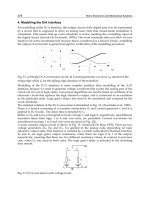
Figure 1 shows the schematic of a typical reformer-combined fuel cell system, which
consists of a fuel reformer and a fuel cell. The fuel reformer is classified into four units; fuel
vaporizer/preheater, steam reformer, combustor/heat-exchanger, and PROX reactor. First,
methanol is fed with water and is heated by the vaporizer. The methanol is reformed by the
reforming catalyst to generate hydrogen in the steam reformer. To supply heat to the steam
reformer, part of hydrogen from the anode off-gas of fuel cell can be fed to the combustor.
The combustor generates the sufficient amount of heat to sustain the methanol reforming
reaction. As mentioned before, the extremely small amount of carbon monoxide deactivates
the fuel cell catalyst, which should be reduced to below 10 ppm by PROX.
Vaporizer
Steam reformer
Combustor
Anode
Electrolyte
Cathode
PROX
H
2
O
Air
Electricity
CH
3
OH
Cartridge
Air
Heat
H
2
Target of the present study
H
2
O
STR
Pump
Air
Fuel reformer Fuel cell
H
2
Fig. 1. Schematic of the fuel cell system combined with the fuel reformer
1.4 Outline of chapter
This chapter presents design, fabrication and evaluation of MEMS methanol reformer. First,
a methanol reformer was fabricated and integrated with a catalytic combustor. Cu/ZnO was
selected as a catalyst for the methanol steam reforming reaction and Pt for the hydrogen
catalytic combustion. Wet impregnation method was used to load the catalysts on a porous
support. The catalyst-loaded supports were inserted in the cavity made on the glass wafer.
The performance of the micro methanol reformer was measured at various test conditions
and the optimum operation condition was sought. Next, new concept of micro methanol
reformer was proposed in the present study. The micro reformer consists of the methanol
reforming reactor, the catalytic decomposition reactor of hydrogen peroxide, and a heat-
exchanger between the two reactors. In this system, the catalytic decomposition of hydrogen
peroxide is used as a process to supply heat to the reforming reactor. The decomposition
process of hydrogen peroxide produces water vapor and oxygen as a product, which can be
used efficiently to operate the reformer/PEMFC system. Microreactor was fabricated for
Micro Electronic and Mechanical Systems
30
preferential oxidation of carbon monoxide using a photosensitive glass process integrated
with a catalyst coating process. A γ-Al
2
O
3
layer was coated as a catalyst support on the
surface of microchannels using sol-gel method. The wet impregnation method was used to
load Pt/Ru in the support. The conversion of carbon monoxide was measured with varying
the ratio of oxygen to carbon (O
2
/C) and the catalyst loading amount. Micro fuel cell was
fabricated and the integrated test with the MEMS methanol reformer was performed to
validate the micro power generation from the micro fuel cell system.
2. Micro reformer integrated with catalytic combustor
2.1 Design
Figure 2 depicts the construction of the integrated micro methanol reformer. The mixture of
methanol and water enters the steam reformer at the top and the reformate gas leaves the
reactor. The mixture of hydrogen and air flows into the catalytic combustor at the bottom
with counter flow stream against the reforming stream. The heat generated from the
catalytic combustor is transferred to the steam reformer through the heat-exchanger layer
that has micro-fins to increase the surface area and the suspended membrane to enhance the
heat transfer rate. The porous catalyst supports were inserted in the cavity made on the
glass wafer as shown in Fig. 2. The micro reformer structure was made of five glass wafers;
two for top and bottom, one for the steam reformer, one for the catalytic combustor, and the
reminder for the heat-exchanger in-between.
CH
3
OH + H
2
O
3H
2
+ CO
2
H
2
+ 0.5O
2
H
2
O
Cu/ZnO
Pt
CH
3
OH+H
2
O
3H
2
+CO
2
H
2
+0.5O
2
H
2
O
Cu/ZnO/support
Pt/support
Cover 1
Steam reformer
Cover 2
Catalytic combustor
Heat exchanger
microchannel
Suspended
membrane
CH
3
OH+H
2
O
3H
2
+CO
2
H
2
+0.5O
2
H
2
O
Cu/ZnO/support
Pt/support
Cover 1
Steam reformer
Cover 2
Catalytic combustor
Heat exchanger
microchannel
Suspended
membrane
Fig. 2. Construction of the integrated micro methanol reformer
The porous ceramic material (ISOLITE
®
) was used as a catalyst support due to its large
surface area and thermal stability (Kim et al., 2007). The typical ceramic support is
composed of 40% Al
2
O
3
and 55% SiO
2
with traces of the other metal oxides, and the porosity
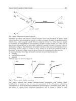
is approximately 71%. Figure 3 shows SEM images of the support material. The scale of the
Micro Power Generation from Micro Fuel Cell Combined with Micro Methanol Reformer
31
bulk pores was between 100 and 300 μm, while smaller scale pores were a few microns. This
structure of the porous support can enhance the heat and mass transport between catalyst
active sites and reactants.
Fig. 3. SEM images of the porous ceramic material used as a catalyst support
2.2 Fabrication
The overall fabrication process was integrated with a catalyst loading step as shown in Fig.
4. The fabrication process for an individual glass wafer is as follows: (1) exposure to
ultraviolet (UV) light under a mask at the intensity of 2 J/cm
2
; (2) heat treatment at 585 ˚C
for 1 hour to crystallize portion of the glass that was exposed to UV; and (3) etching the
crystallized portion of the glass in the 10% hydrofluoric (HF) solution to result in the desired
shape. The etching rate was 1 mm per hour. With step 1-3 in Fig. 4, two covers, a reformer
layer, and a combustor layer were fabricated. To obtain the membrane heat-exchanger, the
glass wafer was exposed by UV light on both sides of the wafer. After the heat treatment,
the wafer was etched standing in the etching bath. The tooth shape cross-section of the
membrane heat-exchanger layer was fabricated by controlling etching time as shown in the
step 4-6 of Fig. 4. The complete micro methanol reformer was constructed by fusion-
bonding the fabricated glass layers, where the porous catalyst supports were inserted in the
reformer layer and the combustor layer, respectively. The best fusion-bonding between glass
wafers was obtained by pressing the wafers against each other at 1000 N/m
2
in a furnace
held at 500 ˚C (Kim & Kwon, 2006a).
As a final step, the catalysts were loaded on the porous catalyst supports. The Cu/ZnO was
selected as a catalyst for methanol reforming reaction, considering its proven reactivity and
selectivity (Kim & Kwon, 2006b). The Pt was chosen as a catalyst for the hydrogen catalytic
combustion. The wet impregnation method was used to load both catalysts on the porous
supports. A mixture of a 0.7 M aqueous solution of Cu(NO
3
)
2
and a 0.3 M aqueous solution
of Zn(NO
3
)
2
was prepared. The mixture was injected in the catalyst support inserted in the
reformer layer using a syringe pump. The moisture was removed by drying the catalyst-
loaded support in a convection oven at 70 ˚C for 12 hours. Calcination procedure followed
in a furnace at 350 ˚C for 3 hours. The similar procedures were used for Pt coating with 1 M
aqueous solution of H
2
PtCl
6
. The amount of the loaded Cu/ZnO was 7.0 wt % while Pt was
5.0 wt % of the total weight of the catalyst support. The catalysts were reduced for 4 hours in
an environment of mixture of 4% H
2
in N
2
, which is steadily flowing into the reformer at a
rate of 10 ml/min in a furnace of 280 ˚C.
Micro Electronic and Mechanical Systems
32
Figure 5 shows the fabrication results, including etched glass wafers, a complete micro
methanol reformer, a cross-section view of the reformer and SEM image of the membrane
heat-exchanger. The total volume of the reformer was 3.6 cm
3
(20 mm×30 mm×6mm) and
the weight was approximately 13.4 g.
Fig. 4. Overall fabrication procedure of the micro methanol reformer.
Cover 1
Reformer
Heat exchanger
Combustor
Cover 2
Catalyst
Hydrogen
Methanol-water
3.6 cm
3
13.4 g
Photosensitive glass
Pt/support
Cu/ZnO/support
Heat exchanger
Fig. 5. Fabricated results of the micro methanol reformer
7. Fusion-bonding
FORTURAN glass (1mm)
Illuminated glass
Crystallized glass
Porous catalyst support
1. UV exposure
Heat exchanger
4. Double-faced UV exposure
5. Heat treatment
6. HF Glass etching
Cr mask
2. Heat treatment
3. HF Glass etching
Catalyst
support
8. Catalyst coating
Cu/ZnO
/support
Pt/support
7. Fusion-bonding
FORTURAN glass (1mm)
Illuminated glass
Crystallized glass
Porous catalyst support
FORTURAN glass (1mm)
Illuminated glass
Crystallized glass
Porous catalyst support
1. UV exposure
Heat exchanger
4. Double-faced UV exposure
5. Heat treatment
6. HF Glass etching
Cr mask
2. Heat treatment
3. HF Glass etching
Catalyst
support
8. Catalyst coating
Cu/ZnO
/support
Pt/support
Micro Power Generation from Micro Fuel Cell Combined with Micro Methanol Reformer
33
2.3 Performance measurement
Experimental setup was equipped to measure the performance of the micro methanol
reformer. A syringe pump (KDS200, KD Scientific) supplied a mixture of methanol and
water to the reformer at a controlled rate. The flow rate of hydrogen and air was controlled
by mass flow controllers (EL-FLOW, Bronkhorst). After mixed them in a mixing chamber,
the mixture gas was supplied to the combustor. The temperature of each reactor was
recorded by thermocouples. The product gas of the reformer was cooled and the
condensable portion was removed in a cold trap. The non-condensable product gas was
analyzed by a gas chromatography (Agilent HP6890). The flow rate of dry gas was
measured by a bubble meter. The column in the gas chromatography was Carboxen-1000
(60/80 mesh, 1/8”, 18 ft) that can separate H
2
, N
2
, CO, CO
2
, CH
4
and others. Nitrogen
carrier gas at known flow rate was mixed with the product gases before entering the gas
chromatography. The exact hydrogen production rate can be calculated by comparing the
ratio of hydrogen to nitrogen because the flow rate of the carrier gas is known. The gas
composition was detected by a TCD (thermal conductivity detector) with Ar as a reference
gas. The product gas of the catalytic combustor was analyzed, after moisture was removed
in a cold trap.
The energy balance between the methanol reformer and the catalytic combustor was
calculated as shown in Table 2. The total heating energy consists of the energy to raise the
reformer temperature and the heat of reaction. The heat of reaction is the sum of the
reforming heat, the evaporation heat and the heat to raise mixture to reforming temperature
(sensible heating). The energy to reform 1 mole methanol with 1 mole water is 158.3 kJ,
which can be provided by burning 0.66 mole hydrogen by the catalytic combustor. The
hydrogen can be provided by recycling the off-gas of the fuel cell. The reformer produces 2.7
moles hydrogen from 1 mole methanol when methanol conversion is 95% and hydrogen
selectivity is 95%. Assuming that hydrogen utilization of the fuel cell is 72%, the amount of
the hydrogen off-gas is 0.756 mole, which is greater than the hydrogen requiremnt for the
combustor to sustain the reformer. Based on this calculation, the expected production of
hydrogen is 54.5 ml/min when the methanol feed rate is 2 ml/h. The fuel cell consumes 72%
portion (39.2 ml/min) in the reformed hydrogen and the remainder (15.3 ml/min) can be
used to operate catalytic combustor.
Calculation Flow rate
Methanol input 1 mol 2 ml/h
Energy requirement for the reformer
*
153.8 kJ
Evaporation and sensible heating of methanol 48.4 kJ
Evaporation and sensible heating of water 51.5 kJ
Heat of reaction 58.4 kJ
Expected production of hydrogen
**
2.7 mol 54.5 ml/min
Hydrogen requirement for the combustor 0.66 mol 13.3 ml/min
Anode off-gas of fuel cell
***
0.756 mol 15.3 ml/min
*
Reforming temperature: 250 ˚C,
**
95% methanol conversion, 95% hydrogen selectivity,
***
Fuel cell utilization: 72%
Table 2. Energy balance calculation between the methanol reformer and the combustor
Micro Electronic and Mechanical Systems
34
2.4 Results and discussion
The performance of the reformer was measured at various test conditions and an optimum
operation condition was sought. The measured performance of the reformer was expressed
in terms of the methanol conversion, which is defined as follows:
3in 3out
3
3in
mol (CH OH) mol (CH OH)
CH OH conversion [mol%] = 100
mol (CH OH)
−
×
(4)
Figure 6 shows the methanol conversion as a function of the reformer temperature at each
methanol feed rate with the steam-to-carbon ratio of 1.1. The methanol conversion
decreased as the methanol feed rate increased, while the methanol conversion increased as
the reformer temperature increased. The maximum methanol feed rate was 2 ml/h to obtain
the methanol conversion higher than 90% at temperature lower than 250 ˚C. At the feed rate
of 2 ml/h and the reformer temperature of 250 ˚C, the hydrogen production rate was 53.9
ml/min and the composition of carbon monoxide in the reformate gas was 0.49%.
Temperature (
o
C)
Methanol conversion (%)
210 230 250 270 290
0
20
40
60
80
100
1.0 ml/h
2.0 ml/h
4.0 ml/h
Fig. 6. Methanol conversion as a function of the reformer temperature
The performance of the catalytic combustor was measured at various conditions. Figure 7
shows the temperature variation of the catalytic combustor as a function of the reaction time
at an equivalence ratio of 1.0. This plot includes the change of reformer temperature, which
has to reach 250 ˚C to obtain the optimal methanol conversion. The temperatures of
reformer and catalytic combustor were measured as varying the hydrogen feed rate. The air
was mixed with hydrogen in the mixing chamber at the equivalent ratio of 1.0 and the gas
mixture was fed into the combustor. In the energy balance calculation, the hydrogen
requirement of the combustor was 15.3 ml/min to sustain the methanol reforming reaction
at the methanol feed rate of 2 ml/h. At the feed rate of 15.3 ml/min, the temperature of the
catalytic combustor reached 148.7 ˚C when 18 min elapsed after the initiation of the reaction.
The hydrogen feed rate increased to reduce the time for the startup of the reformer. At the
hydrogen feed rate of 41.3 ml/min, the combustor temperature reached 271 ˚C within 8.6
min after the start of operation and the reformer temperature was 250 ˚C. As the hydrogen
feed rate increased, the combustion heat increased and the time for startup decreased.
However, the hydrogen conversion decreased at the increase of the hydrogen feed rate due
to the short residence time that is proportional to the inverse of the feed rate. Furthermore,
Micro Power Generation from Micro Fuel Cell Combined with Micro Methanol Reformer
35
the hot-spot appeared in the fore part of the combustor, which can damage the catalyst and
the reactor substrate. The temperature difference between the reformer and the combustor
increased with the hydrogen feed rate. At the feed rate of 41.3 ml/min, the temperature
difference was 21 ˚C when the reformer temperature reached 250 ˚C.
Time (min)
Temperature (
o
C)
0 3 6 9 12 15 18
0
50
100
150
200
250
300
350
41.3 ml/min
30.5 ml/min
15.3 ml/min
Reformer
Combustor
Fig. 7. Temperature variation of the catalytic combustor as a function of the reaction time.
Figure 8 represents the result of simultaneous operation of the methanol steam reformer and
the catalytic combustor. The reformer was heated up to 250 ˚C by an external preheater with
the increasing rate of temperature of 11.4 ˚C/min. The combustor was operated when the
reformer temperature reached 250 ˚C. The hydrogen feed rate was 15.3 ml/min, which can
be supplied from the anode off-gas of fuel cell when the methanol feed rate is 2 ml/h. The
air was mixed with hydrogen to fix the equivalent ratio at 1.0. The methanol was fed into the
reformer with the feed rate of 2 ml/h. The water feed rate was 0.98 ml/h to satisfy the
steam-to-carbon ratio of 1.1. The reformer temperature was maintained constantly after the
methanol reforming reaction was initiated. After 8 minutes into the simultaneous operation,
steady reforming reaction was attained and the methanol conversion was higher than 90%.
The maximum conversion of methanol was 95.7%. The temperature difference between the
reformer and the combustor was approximately 4 ˚C.
Fig. 8. Simultaneous operation of the methanol steam reformer and the catalytic combustor
Time (min)
Temperature (
o
C)
Methanol conversion (%)
0 102030405060
0
50
100
150
200
250
300
0
20
40
60
80
100
Preheating Operating combustor
Micro Electronic and Mechanical Systems
36
Time (min)
Reformate gas composition (mol%)
H
2
production rate (ml/min)
30 40 50 60
0
20
40
60
80
100
0
10
20
30
40
50
60
CO
2
CO
H
2
Fig. 9. The composition of reformate gas and the production rate of hydrogen
Figure 9 shows the composition of reformate gas and the hydrogen production rate after the
start of complete operation. As the steady reforming reaction lasted, the composition of
reformate gas remained constant. The reformate gas composition was 74.4% H
2
, 24.36% CO
2
,
and 1.24% CO, and its flow rate was 67.2 ml/min. The hydrogen production rate was
approximately 50 ml/min, which can generate 4.5 W electric power on a typical PEMFC.
The concentration of carbon monoxide at the integrated test was higher than that at the
separate test of the reformer. Although the catalytic combustor gave the sufficient amount of
heat to operate the reformer, it could not form uniform temperature distribution within the
reformer. As a result, the high temperature gradient occurred in the reformer, increasing the
selectivity of carbon monoxide. The thermal efficiency of the conventional reformer
combined with the combustor is defined by:
2
32
H_produced
T
CH OH_reformer H _combustor
LHV
η = 100
LHV LHV
×
−
(5)
where the LHV means the lower heating value. The thermal efficiency of the integrated
micro methanol reformer was 76.6%. The operating conditions and the performance of the
micro methanol reformer is summarized in Table 3.
Operating condition Reformer Combustor
Feed flow rate 2 ml/h CH
3
OH 15.3 ml/min H
2
S/C (steam-to-carbon ratio) 1.1
Equivalence ratio 1.0
Temperature 250 ˚C 251 ˚C
Performance Reformer only Integrated operation
Temperature 247 ˚C (reformer)
Conversion 96.2% 95.7%
H
2
production rate 53.9 ml/min
50 ml/min
CO composition 0.49% 1.24%
Thermal efficiency 76.6%
Table 3. The operating conditions and the performance of the micro methanol reformer
Micro Power Generation from Micro Fuel Cell Combined with Micro Methanol Reformer
37
3. Micro reformer heated by hydrogen peroxide decomposition
3.1 Hydrogen peroxide as a heat source
In the previous section, the catalytic combustor is used as a heat source of the methanol
steam reformer. However, it is still problematic that non-uniform distribution of reaction
and hot spot formations in the fore region of the combustor. In the present study, the
catalytic decomposition of hydrogen peroxide is used as a process to supply heat to the
reformer. The decomposition reaction of hydrogen peroxide is expressed below:
o
22 2 2 f
H O H O 0.5O , ΔH = 54.24kJ/mol→+ − (6)
The construction of the micro methanol reformer complete with a heat source is presented in
Fig. 10, in which the catalytic reactor for the hydrogen peroxide decomposition is included.
The hydrogen peroxide decomposition is a highly exothermic reaction and generates the
sufficient amount of heat to sustain the methanol steam reforming reaction. The catalytic
decomposition of hydrogen peroxide has great reactivity and selectivity on various metal
elements, such as Fe, Cu, Ni, Cr, Pt, Pd, Ir, and Mn (Teshima et al., 2004). The hydrogen
peroxide decomposition generates steam and oxygen as products. The steam can be recycled
into the reformer for the steam reforming reaction. The oxygen can be used as an oxidizer at
the fuel cell cathode and to remove carbon monoxide in the preferential oxidation. The
present concept renders the system far more compact than the existing reformer/combustor
model because hydrogen peroxide is stored and used in condensed phase and oxygen
enrichment enhances the system efficiency.
In the present study, the performance evaluation of the methanol steam reformer with
hydrogen peroxide heat source was carried out at various test conditions and an optimum
operation condition was sought.
Vap or iz er
Steam reformer
H
2
O
2
heat source
Anode
Electrolyte
Cathode
PROX
H
2
O
O
2
Electricity
H
2
O
2
Cartridge
CH
3
OH
Cartridge
O
2
Heat
H
2
Target of the present study
Fig. 10. Concept of methanol steam reformer integrated with hydrogen peroxide heat source
3.2 Experimental
Experimental apparatus for the performance measurement of the reformer system is similar
with the combustor experiment. Two syringe pumps supplied reactants to the reactor at a
controlled rate; one for the mixture of methanol and water, and the other for hydrogen
peroxide. The temperature of each reactor was recorded by thermocouples. The analysis of
the product gas composition was the same with the section 2.3. The concentration of
Micro Electronic and Mechanical Systems
38
hydrogen peroxide was measured using a refractometer (PR-50HO, ATAGO) with a small
quantity of sample. The product gas of hydrogen peroxide decomposition was analyzed,
after moisture removed in a cold trap.
The measured performance of the reformer was expressed in terms of the methanol
conversion, hydrogen selectivity and hydrogen peroxide conversion, which are defined as
follows:
3in 3out
3
3in
mol (CH OH) mol (CH OH)
CH OH conversion [mol%] = 100
mol (CH OH)
−
× (4)
2
2
3in 3out
mol (H ) 1 3
H selectivit
y
[%] = 100
mol (CH OH) mol (CH OH)
×
×
−
(7)
22in 22out
22
22in
mol (H O ) mol (H O )
H O conversion [mol%] = 100
mol (H O )
−
× (8)
3.3 Operation parameter
The chemical equation of methanol steam reforming reaction is expressed below:
32222
CH OH sH O 3H CO (1-s)H O
+
→++ (9)
where symbol s is the molal ratio of water to methanol (H
2
O/CH
3
OH), which is the same
with the steam-to-carbon ratio. Decomposition reaction of hydrogen peroxide is expressed
below:
22 2 2 2
a(xH O (1-x)H O)) 0.5axO (1 x ax)H O
+
→+−+ (10)
where symbol a and x are the molal ratio of hydrogen peroxide to methanol (H
2
O
2
/CH
3
OH)
and the molal concentration of hydrogen peroxide, respectively. The performance of the
reformer system depends on these parameters. In order to determine the reaction condition,
the concentration of hydrogen peroxide and the weight hourly space velocity (WHSV) were
used as control parameters. The weight hourly space velocity indicates the ratio of the
reactant flow rate to the catalyst mass as follows:
Molal flow rate of reactants (mol/h)
WHSV= [mol/
g
-h]
Catalyst mass (g)
(11)
Overall heat output of the integrated reformer system was calculated as shown in Fig. 11.
Figure 11 (a) shows the variation in the decomposition reaction heat of hydrogen peroxide
as a function of the weight concentration of hydrogen peroxide. It can be seen that the
hydrogen peroxide concentration has to be higher than 73.9 wt % to generate the sufficient
heat to complete the reforming reaction of methanol at s = 1.0 and a = 9.0, respectively.
Hydrogen peroxide with even higher concentration is needed when the steam-to-carbon
ratio is higher or the hydrogen peroxide-to-methanol ratio is lower.
Figure 11 (b) illustrates the net heat output that amounts to the difference between the
decomposition heat of hydrogen peroxide and the heat required to maintain the reformer at
the optimum operation condition. The decomposition heat of 5.3 moles hydrogen peroxide
Micro Power Generation from Micro Fuel Cell Combined with Micro Methanol Reformer
39
at 81.5 wt % concentration releases the sufficient amount of heat to reform the mixture of 1
mole methanol and 1 mole water. The required amount of hydrogen peroxide will decrease
when the hydrogen peroxide concentration increases or the steam-to-carbon ratio decreases.
In the calculation that leaded to Fig. 11, the heat loss to the surrounding was ignored.
Considering the heat loss of the reformer, higher concentration of hydrogen peroxide or
higher hydrogen peroxide-to-methanol ratio is required. In the present study, hydrogen
peroxide of 82 wt % concentration was used and the steam-to-carbon ratio was fixed at 1.1
for convenience in the experiment. The performance characteristics of the reformer was
investigated with three control parameters; methanol space velocity, hydrogen peroxide
space velocity, and hydrogen peroxiode-to-methanol ratio.
(a) (b)
Fig. 11. Overall heat output of the integrated reformer system
3.4 Results and discussion
The temperature of the hydrogen peroxide decomposition reactor was measured as varying
the hydrogen peroxide space velocity. Figure 12 (a) shows the temperature of the hydrogen
peroxide decomposition reactor as a function of reaction time at each space velocity, in
which the hydrogen peroxide conversion is included. At the space velocity of 6.32 mol/g-h,
the hydrogen peroxide conversion was 98.2% and the reactor temperature reached 150 ˚C
when 200 seconds elapsed after the initiation of reaction. At the space velocity of 37.3
mol/g-h, the reactor temperature reached 250 ˚C, which is the optimal temperature for the
methanol reforming reaction, within a minute after the start of operation. The amount of
reaction heat increases with the feed rate of hydrogen peroxide, reducing the time to obtain
the optimal reformer temperature. At high space velocity, however, reactants does not take
the residence time enough to react on the catalyst, resulting in the decrease of hydrogen
peroxide conversion. At the low space velocity, the temperature difference between the
reformer and the decomposition reactor was within 5 ˚C. At the space velocity of 37.3
mol/g-h, however, the temperature difference increased with the time after the start-up as
shown in Fig. 12 (b). When the temperature of decomposition reactor reached 250 ˚C, the
reformer temperature was less than 200 ˚C.
Figure 13 represents the simultaneous operation result of the methanol steam reformer and
the hydrogen peroxide decomposition reactor. The reformer was heated up to 250 ˚C by the
decomposition reactor with 82 wt% hydrogen peroxide at the space velocity of 9.48 mol/g-
H
2
O
2
concentration (wt%)
ΔH
R
(l), Reaction heat (kJ/mol)
30 40 50 60 70 80 90 100
-500
-400
-300
-200
-100
0
100
200
300
400
500
s=1.0, a=9.0
s=2.0, a=9.0
s=3.0, a=9.0
s=1.0, a=5.0
s=1.0, a=13.0
R: CH
3
OH + sH
2
O
H: a(xH
2
O
2
+ (1-x)H
2
O)
a, H
2
O
2
/CH
3
OH (mol/mol)
ΔH
R
(l), Reaction heat (kJ/mol)
012345678910
-400
-300
-200
-100
0
100
200
300
400
s=1.0, x=0.7 (81.5 wt%)
s=2.0, x=0.7 (81.5 wt%)
s=3.0, x=0.7 (81.5 wt%)
s=1.0, x=0.6 (73.9 wt%)
s=1.0, x=0.8 (88.3 wt%)
R: CH
3
OH + sH
2
O
H: a(xH
2
O
2
+ (1-x)H
2
O)
Micro Electronic and Mechanical Systems
40
h. The mixture of methanol and water was fed into the reformer with the steam-to-carbon
ratio at 1.1. The space velocity of methanol was 0.68 mol/g-h. The temperature increased
steadily after the methanol reforming reaction was initiated. It implies that the hydrogen
peroxide feed rate exceeds the minimum to sustain the methanol reforming reaction. By
reducing the feed rate down to the space velocity of 6.32 mol/g-h after 5 minutes into the
operation, an ideal reaction condition was obtained as shown in Fig. 13. After 8 minutes into
the operation, steady methanol reforming reaction was obtained and the methanol
conversion was higher than 91.2%. The temperature inside the reformer and the
decomposition reactor were 253 ˚C and 278 ˚C, respectively.
Reaction time (sec)
Reactor temperature (
o
C)
0 50 100 150 200 250 300
0
50
100
150
200
250
300
37.3
6.32
3.16
Conv. (%)
WHSV (mol/g-h)
99.6
98.4
72.0
Reaction time (sec)
Temperature (
o
C)
0 102030405060
0
50
100
150
200
250
300
H
2
O
2
reac to r
Reformer
(a) (b)
Fig. 12. The performance of hydrogen peroxide decomposition reactor
Reaction time (min)
Temperature (
o
C)
Methanol conversion (%)
048121620
0
50
100
150
200
250
300
350
0
25
50
75
100
125
150
H
2
O
2
re ac to r
Reformer
Conversion
B
A
Fig. 13. Simultaneous operation of the micro reformer with hydrogen peroxide heat source
The performance characteristics of the micro reformer with hydrogen peroxide heat source
was investigated at various conditions. Figure 14 (a) shows the effect of the methanol space
velocity on the methanol conversion and the reformer temperature with the conditions of
Micro Power Generation from Micro Fuel Cell Combined with Micro Methanol Reformer
41
the decomposition reactor fixed (S/C = 1.1, 82 wt% H
2
O
2
, H
2
O
2
WHSV 6.32 mol/g-h). As the
methanol space velocity increased, the reformer temperature decreased gradually because
the hydrogen peroxide decomposition heat was consumed to vaporize the methanol
supplied in liquid phase. As a result, the reformer decreased in temperature and did not
sustain the methanol reforming reaction. Figure 14 (b) shows the effect of the reformer
temperature on the methanol conversion. The feed rate of the methanol was fixed while the
reformer temperature was determined by varying the feed rate of hydrogen peroxide
(CH
3
OH WHSV 0.68 mol/g-h, S/C = 1.1, 82 wt% H
2
O
2
). The reformer temperature
increased with the space velocity of hydrogen peroxide because the decomposition heat of
hydrogen peroxide increased. The methanol conversion increased with the reformer
temperature, when the temperature was below 250 ˚C. For the reformer temperature higher
than 250 ˚C, the methanol conversion maintained its value at 250 ˚C.
(a) (b)
Fig. 14. Performance characteristics of micro reformer with hydrogen peroxide heat source
Fig. 15. Hydrogen selectivity and thermal efficiency as a function of reformer temperature
Figure 15 shows the hydrogen selectivity and the thermal efficiency of the system as a
function of reformer temperature with the conditions of the reformer fixed. The thermal
efficiency of the conventional reformer/combustor model is defined by:
Reformer temperature (
o
C)
Hydrogen selectivity (%)
Thermal efficienc
y
(
%
)
220 240 260 280 300
0
20
40
60
80
100
0
20
40
60
80
100
Hydrogen selectivity
Thermal efficiency
Reformer temperature (
o
C)
Methanol conversion (%)
H
2
O
2
WHSV (mol/g-h)
220 240 260 280 300
0
20
40
60
80
100
0
2
4
6
8
10
12
14
Methanol conversion
H
2
O
2
WHSV
CH
3
OH WHSV (mol/g-h)
Methanol conversion (mol %)
R
eformer tem
p
erature
(
o
C
)
0.4 0.8 1.2 1.6
0
20
40
60
80
100
160
180
200
220
240
260
280
Methanol conversion
Reformer temperature
Micro Electronic and Mechanical Systems
42
2
32
H_produced
T
CH OH_reformer H _combustor
LHV
η = 100
LHV LHV
×
−
(5)
This formula could not be applied to the methanol reformer integrated with the hydrogen
peroxide decomposition reactor, because the LHV of hydrogen peroxide is not defined. In
the present study, the thermal efficiency for the reformer system is defined as follows:
2
322
R
H_produced
T
RR
CH OH_reformer H O
ΔH
η = 100
ΔH ΔH
′
×
−
(12)
The LHV was replaced with the heat of reaction. The LHV of hydrogen provided to the
combustor in Eq. 5 was replaced with the decomposition heat of hydrogen peroxide. The
hydrogen selectivity increased with the thermal efficiency as the reformer temperature
increased. At the reformer temperature higher than 250 ˚C, however, the hydrogen
selectivity decreased as the reformer temperature increased, because the production of
carbon monoxide increased. The maximum hydrogen selectivity and the thermal efficiency
were 86.4% and 44.8%, respectively. The product gas included 74.1% H
2
, 24.5% CO
2
and
1.4% CO, and the total volume production rate was 23.5 ml/min. The hydrogen production
rate is the sufficient amount to generate 1.5 W electrical power on a typical PEMFC. The
optimum condition and the performance of the methanol reformer with hydrogen peroxide
heat source are shown in Table 4.
The overall efficiency of typical PEMFC system using a methanol reformer is approximately
40% (Ishihara et al., 2004). In present study, the exergy loss can be reduced by the use of
hydrogen peroxide decomposition reaction. The use of oxygen generated by the
decomposition reaction raises the cell voltage, resulting in the increase of the fuel cell
efficiency. It is understood that the overall efficiency of fuel cell system presented in present
study is higher than that of the existing fuel cell model.
H
2
O
2
reactor Reformer
Temperature 278 ˚C 253 ˚C
S/C (steam-to-carbon ratio) 1.1
H
2
O
2
concentration 82 wt%
Feed flow rate 2 ml/h 10 ml/h
WHSV 0.68 mol/g-h 6.32 mol/g-h
Conversion 98.4 % 91.2 %
H
2
production rate 23.5 ml/min
CO composition 1.4 %
Hydrogen selectivity 86.4%
Thermal efficiency 44.8%
Table 4. The optimum operation conditions and the performance of the integrated reformer
4. Integrated test with micro fuel cell
4.1 Removal of carbon monoxide
Removal of carbon monoxide from the reformate gas mixture is of paramount importance
for development of a reformer in fuel cell applications because carbon monoxide deactivates
Micro Power Generation from Micro Fuel Cell Combined with Micro Methanol Reformer
43
the anode catalyst of PEMFC. There are several processes for the carbon monoxide removal
including pressure/temperature swing adsorption (PSA/TSA), methanation, membrane
separation, and preferential oxidation. PSA/TSA are energy-intensive and expensive.
Methanation consumes three moles of hydrogen to convert 1 mole CO into 1 mole methane
as given below:
+→ +
242
CO 3H CH H O (13)
It is therefore not recommended. The membrane separation is attractive method because
high purity hydrogen can be obtained. PROX also is the preferred method because the small
amount of oxygen is required to oxidize CO into CO
2
as expressed below:
22
CO 1 2O CO+→ (14)
4.2 Microreactor for preferential oxidation
Microreactor for PROX was prepared as shown in Fig. 16. Pt/Ru was selected as a catalyst
of PROX. Microchannels were fabricated on a photosensitive glass.
Cover
Microchannel
Fig. 16. Microreactor for preferential oxidation
As a washcoat layer, γ-Al
2
O
3
was coated on the microchannels using sol-gel method and the
catalyst was loaded by wet impregnation method. First, aluminum isopropoxide was
hydrolyzed in deionized water with vigorous stirring for 1 hour at 80 ˚C. The sol was
peptized by adding nitric acid (HNO
3
) with adjusting the pH. Polyvinyl alcohol (PVA)
solution was prepared by dissolving the PAV in deionized water at 75 ˚C. The presence of
PVA can reduce crack formations of the washcoat layer at the drying time. The peptized sol
and the PVA solution were mixed with adding the γ-Al
2
O
3
powder to increase the
concentration of γ-Al
2
O
3
in the slurry. The mixture slurry was ball-milled for 72 hours. The
glass substrate was then dipped into the prepared γ-Al
2
O
3
slurry and dried for 2 hours at
120 ˚C after blowing off the excess slurry. This procedure was repeated to obtain the desired
weight of the γ-Al
2
O
3
washcoat layer. The washcoated microchannels were then calcined at
350 ˚C for 4 hours. A mixture of a 0.5 M aqueous solution of H
2
PtCl
6
and a 0.5 M aqueous
solution of RuCl
3
were prepared. The substrate was immersed in the mixture for 12 hours.
The moisture was removed by drying the catalyst-loaded substrate in a convection oven at
70 ˚C for 12 hours. The calcination followed in a furnace at 350 ˚C for 3 hours. The catalyst
was activated by reduction in a steady flowing hydrogen environment at 350 ˚C for 5 hours.
The carbon monoxide conversion of PROX reactor as a function of the reaction temperature
with varying the ratio of oxygen to carbon is shown in Fig. 17. Mixture gas including 69.91%
H
2
, 3.06% CO, 2.03% CH
4
, and 25% CO
2
was used in the test of PROX reactor. The carbon
monoxide conversion increased with the oxygen-to-carbon ratio and the reactor
Micro Electronic and Mechanical Systems
44
temperature. In the case of 5 wt% Pt/Ru/γ-Al
2
O
3
catalyst, the carbon monoxide was
removed completely with oxygen-to-carbon ratio of 4 at 200 ˚C.
Temperature (
o
C)
CO conversion (%)
100 120 140 160 180 200 220
0
20
40
60
80
100
O
2
/CO = 1, 1% Pt/Ru
O
2
/CO = 2, 1% Pt/Ru
O
2
/CO = 3, 1% Pt/Ru
O
2
/CO = 4, 1% Pt/Ru
O
2
/CO = 4, 5% Pt/Ru
Fig. 17. Conversion of carbon monoxide of PROX microreactor
4.3 Integrated test with micro fuel cell
MEMS fuel cell was fabricated for integrated tests with the micro reformer. The structure of
the micro fuel cell is shown in Fig. 18. Membrane electrode assembly (MEA) was prepared
by coating 0.3 mg/cm
2
Pt-Ru/C for an anode catalyst and 0.3 mg/cm
2
Pt/C for a cathode
catalyst on a Nafion-112 membrane. The reason to select Pt-Ru/C as an anode catalyst is
because Pt/C is poisoned by carbon monoxide in the reformate gas even if removed via
PROX reaction. Carbon paper (TGP-H-090, 260 μm) was used as a gas diffusion layer (GDL).
Flow channels were fabricated by etching the photosensitive glass wafer, on which the
current collectors, Ag/Ti layer, were sputtered. Overall fabrication process is presented in
Fig. 18 and the fabricated micro fuel cell is shown in Fig. 19.
Cathode Anode
GDL GDLMEA
Nafion-112
PtRu/C
Pt/C
Carbon paper
Assembly
Ag/Ti
Fig. 18. Structure and fabrication process of MEMS fuel cell
Experimental layout for integrated tests of the reformer with the micro fuel cell is shown in
Fig. 20. The micro fuel cell was tested with pure hydrogen to compare with the result with
the reformate gas. Simultaneous operation of the micro reformer, PROX reactor, and micro
fuel cell was carried out.
Micro Power Generation from Micro Fuel Cell Combined with Micro Methanol Reformer
45
< Anode side >
< Cathode side >
Fig. 19. Fabricated results of the micro fuel cell
Thermal insulation
CH
3
OH
+ H
2
O
H
2
H
2,
CO
2,
CO
Anode
off-gas
Electricity
Air
Methanol reformer
PROX reactor
Micro fuel cell
Fig. 20. Schematic of the integrated test of micro reformer-PROX reactor-micro fuel cell
4.4 Results and discussion
Performance of MEMS fuel cell system with pure hydrogen and the reformate gas is shown
in Fig. 21. Pure hydrogen gas feed rate was set in 50 ml/min. When methanol feed rate was
Micro Electronic and Mechanical Systems
46
2 ml/h, the flow rate of reformate gas was 71.96 ml/min. The reformate gas included 74.4%
hydrogen, thus the hydrogen flow was 53.5 ml/min. The power density was 184 mW/cm
2
when the potential was 0.64 V. The performance was low compared with the result for pure
hydrogen due to the feed at the fuel cell that included undesired CO, CO
2
, and N
2
.
Current density (mA/cm
2
)
Potential (V)
Power density (mW/cm
2
)
0 100 200 300 400 500 600
0
0.2
0.4
0.6
0.8
1
0
50
100
150
200
250
300
Pure hydrogen
Reformate gas
Pure hydrogen
Reformate gas
Fig. 21. Performance curve of MEMS fuel cell system
Specific energy density of the micro fuel cell system was calculated to compare with the
state-of-art batteries. First, the overall energy budget for operation of the fuel cell system
was calculated. Figure 22 presents the energy specification of each reaction step.
Reformer
95% conversion
95% selectivity
PROX
50% selectivity
Fuel cell
72% utilization
60% efficiency
0.219 mol/h CH
3
OH
0.241 mol/h H
2
O
(S/C = 1.1)
0.594 mol/h H
2
0.01 mol/h CO
0.583 mol/h H
2
0.01 mol/h O
2
0.163 mol/h H
2
Combustor
98% conversion
9.956 W
20 W
10.658 W
0.81 W
0.163 mol/h O
2
Pump
Heat loss
PMS
0.42 mol/h H
2
O
0.292 mol/h O
2
Fig. 22. Energy budget for a fuel cell system
The 20 W fuel cell system requires the hydrogen of 0.42 mol/hr. Thus, methanol feed rate of
0.219 mol/hr is required, assuming 95% methanol conversion and 95% hydrogen selectivity
of the reformer. The energy requirement of the reformer consists of sensible heat,
vaporization heat, and endothermic reforming reaction heat as given below:
Micro Power Generation from Micro Fuel Cell Combined with Micro Methanol Reformer
47
333
222
338 523
v
p,CH OH(l) p,CH OH(g) CH OH
298 338
373 523
vR
p,H O(l) p,H O(
g
)HO523
298 373
CdTC dTH
CdTC dTHH
++Δ
+ + +Δ +Δ
∫∫
∫∫
(15)
The total energy input for the methanol reformer is 9.956 W. The catalytic combustor
generates 10.658 W heat energy with the fuel cell off-gas of 0.163 mol/hr, which is greater
than the reformer energy requirement. It means that the fuel cell system can be operated
without the additional heat supply to sustain the methanol reforming reaction.
The methanol storage of 4.386 moles is required for the duration of 20 hours (0.219 mol/hr ×
20 hr). The water feed requirement is 0.241 mol/hr at the steam-to-carbon ratio of 1.1, thus
the water storage is 4.825 moles (0.241 mol/hr × 20 hr). These translate into 140.49 g (178.97
cc) methanol, and 87.093 g (87.25 cc) water, respectively. Therefore, the net fuel mixture
storage requirement would be 227.58 g or 266.22 cc.
The specifications of the fabricated fuel cell are: mass of 0.5 g, volume of 2.7 cc, active area of
4 cm
2
, and power density of 180 mW/cm
2
. Thus 20 W fuel cell would have a mass of 13.89 g
(0.5 g × 20 W / (0.18 W/cm
2
× 4 cm
2
)) and a volume of 75 cc. The specific power density of
the micro reformer was 0.34 W/g or 1.25 W/cc. The reformer would have a mass of 59.62 g
and a volume of 16 cc for 20 W fuel cell to be operated in the sufficient hydrogen supply.
Therefore, the mass and volume of the total system were 301 g and 357 cc, respectively.
The energy storage capacity was 400 W·hr (20 W × 20 hr). So, the fuel cell system would
have a weight specific energy density of 1329 W·hr/kg and a volume specific energy density
of 1120 W·hr/L, which are values 10 times higher than the state-of-art of rechargeable
batteries. The system energy density as the duration is shown in Fig. 23. The water
production rate in the fuel cell was 0.42 mol/hr, which is greater than the water supply of
the reformer (0.241 mol/hr) as shown in Fig. 22. Thus, the water from the fuel cell can be
recycled into the reformer, improving the system energy densities. The specific energy
densities for 10 days duration would be 2728 W·hr/kg and 2144 W·hr/L, respectively. It
means that the micro fuel cell system can be an ideal alternative solution for portable micro
power sources in the future.
Duration (hr)
System energy density
0 40 80 120 160 200 240
0
0.5
1
1.5
2
2.5
3
kWhr/kg
kWhr/L
kWhr/kg waterrecycle
kWhr/L water recycle
Fig. 23. System energy density as a function of the duration
Micro Electronic and Mechanical Systems
48
5. Conclusion and future research
5.1 Conclusion
The design, fabrication and performance evaluation of micro methanol reformer integrated
with a heat source were described in this chapter. The micro methanol reformer consists of
the steam reformer, the catalytic combustor, and the heat exchanger in-between. The two
heat sources for the reformer were used; one is the hydrogen catalytic combustion and the
other is the hydrogen peroxide decomposition.
All reactions, the methanol reforming reaction, the hydrogen combustion, and the hydrogen
peroxide decomposition, are the catalytic process. Cu/ZnO was used for the reformer and
Pt for the catalytic combustor. The porous ceramic material was used as the catalyst support
to enhance the catalytic surface area. The catalytic microreactor was fabricated on five
photosensitive glass wafers; top and bottom covers, a reformer layer with Cu/ZnO/support
insert, a combustor layer with Pt/support insert, and a heat exchanger layer in-between.
The performance of the reformer complete with the catalytic combustor was measured. The
methanol conversion was 95.7%, and the thermal efficiency was 76.6%. The reformate gas
flow including three major elements, 74.4% H
2
, 24.36% CO
2
, and 1.24% CO was 67.2
ml/min. The hydrogen flow in the reformate gas was the sufficient amount to run 4.5 W
PEMFC.
The performance characteristics of the methanol reformer with the hydrogen peroxide heat
source was investigated. The methanol conversion over 91.2% and the hydrogen selectivity
over 86.4% were obtained. A modified thermal efficiency using the reaction heat of
hydrogen peroxide instead of the LHV was defined and the thermal efficiency of the system
was 44.8%. The reformate gas flow including 74.1% H
2
, 24.5% CO
2
and 1.4% CO was 23.5
ml/min. This hydrogen was the sufficient amount to run 1.5 W PEMFC. The performance of
the present methanol reformer can be further enhanced by using hydrogen peroxide with
higher concentration.
The microreactor for the PROX reaction was fabricated using the photosensitive glass
process integrated with the Pt/Ru/γ-Al
2
O
3
sol-gel coating process. The carbon monoxide in
the reformate gas was removed to use directly in the micro fuel cell.
The micro fuel cell was fabricated and connected with the micro reformer and PROX
reactor.
The power density of the micro fuel cell system was 184 mW/cm
2
at the potential of 0.64 V
and is lower than that in the case of pure hydrogen test, because the reformate gas included
the undesired CO, CO
2
, and N
2
.
The system energy density of the micro fuel cell system integrated with the methanol
reformer was calculated. The overall energy budget was calculated to operate the reformer-
combined fuel cell system. The system energy storage density of the micro fuel cell system
was obtained in the range of 1329 W·hr/kg to 2728 W·hr/kg. It is estimated that the micro
fuel cell combined with the micro reformer has the energy density of up to 10 times higher
than existing batteries, thus expecting to appear in the mobile energy market of the future.
5.2 Future research
Although the integrated methanol reformer developed in the present study can be used
directly to operate the micro fuel cell, several works may be continued such as a fully
integrated microfabrication, thermal packing, and optimization.
The micro reformer should be insulted thermally to obtain the high thermal efficiency and
the low package temperature of the micro fuel cell system. The excess heat loss of the
Micro Power Generation from Micro Fuel Cell Combined with Micro Methanol Reformer
49
reformer makes the catalytic combustor difficult to sustain the methanol reforming reaction.
The thermal insulation of the reformer facilitates the integration of the reformer with the
micro fuel cell at the low package temperature. The heat loss through conduction and
convention can be prevented by the vacuum packaging technology using an anodic bonding
process. The thermal design of the micro reformer through the extensive modeling of the
heat transfer will be preceded to improve the overall thermal efficiency of the micro fuel cell
system.
The fully integrated microfabrication of the micro fuel cell system is the next challenge to
improve the system packaging efficiency. The batch fabrication of all elements including the
micro reformer, PROX reactor, and micro fuel cell can reduce the fabrication cost. The
overall integrated design of the micro fuel cell system should be optimized in consideration
of the thermal balance and fluidic interconnections between the reactors. The micropump,
microvalve, and control circuitry will be integrated with the micro reformer and micro fuel
cell in the future.
6. Notation
a Molal ratio of hydrogen peroxide to methanol
C
p
Constant pressure specific heat, kJ/mol-K
LHV Lower heating value, kJ/mol
O
2
/C Oxygen-to-carbon ratio
S/C Steam-to-carbon ratio
s Molal ratio of water to methanol
WHSV Weight hourly space velocity, mol/g-h
x Molal concentration of hydrogen peroxide
η
T
Thermal efficiency
∆H
R
Heat of reaction, kJ/mol
∆H
V
Vaporization heat, kJ/mol
7. References
Agrell, J.; Boutonnet, M. & Fierro, J. (2003). Production of hydrogen from methanol over
binary Cu/ZnO catalysts Part II. Catalytic activity and reaction pathways,
Applied
Catalysis A: General
, Vol. 253, pp. 213–223, 0926-860X
Delsman, E.; De Croon, M.; Pierik, A.; Kramer, G.; Cobden, P.; Hofmann, C.; Cominos, V. &
Schouten, J. (2004). Design and operation of a preferential oxidation microdevice
for a portable fuel processor,
Chemical Engineering Science, Vol. 59, pp. 4795-4802,
0009-2509
Holladay, D.; Wainright, S.; Jones, O. & Gano, R. (2004). Power generation using a mesoscale
fuel cell integrated with a microscale fuel processor,
Journal of Power Sources, Vol.
130, pp. 111–118, 0378-7753
Ishihara, A.; Mitsushima, S.; Kamiya, N. & Ota, K. (2004). Exergy analysis of polymer
electrolyte fuel cell systems using methanol,
Journal of Power Sources, Vol. 126, pp.
34–40, 0378-7753
Kim, T. & Kwon, S. (2006a). Design, fabrication and testing of a catalytic microreactor for
hydrogen production,
Journal of Micromechenics and Microengineering, Vol. 16, pp.
1752–1760, 0960-1317
Micro Electronic and Mechanical Systems
50
Kim, T. & Kwon, S. (2006b). Preparation of Cu/ZnO for Fabrication of a Micro Methanol
Reformer,
Chemical Engineering Journal, Vol. 123, No. 3, pp. 93-102, 1369-703X
Kim, T.; Hwang, J. & Kwon, S. (2007). A MEMS methanol reformer heated by decomposition
of hydrogen peroxide,
Lab on a Chip, Vol. 7, No. 7, pp. 836–847, 1473-0197
Kundu, A.; Jang, J.; Lee, H.; Kim, S.; Gil, J.; Jung, C. & Oh, Y. (2006). MEMS-based micro-fuel
processor for application in a cell phone,
Journal of Power Sources, Vol. 162, pp. 572–
578, 0378-7753
Lindstrom, B. & Pettersson, L. (2001). Hydrogen generation by steam reforming of methanol
over copper-based catalysts for fuel cell applications,
International Journal of
Hydrogen Energy
, Vol. 26, pp. 923–933, 0360-3199
Lindström, B.; Agrell, J. & Pettersson, L. (2003). Combined methanol reforming for hydrogen
generation over monolithic catalysts,
Chemical Engineering Journal, Vol. 93, pp. 91–
101, 1369-703X
Lua, G.; Wang, C.; Yen, T. & Zhang, X. (2004). Development and characterization of a
silicon-based micro direct methanol fuel cell,
Electrochimica Acta, Vol. 49, pp. 821–
828, 0013-4686
Nguyen, N. & Chan S. (2006). Micromachined polymer electrolyte membrane and direct
methanol fuel cells—a review,
Journal of Micromechanics and Microengineering, Vol.
16, pp. R1–R12, 0960-1317
O’Hayre, R.; Cha, S.; Colella, W. & Prinz, F. (2006).
Fuel Cell Fundamentals, pp. 10-11, John
Wiley & Sons, Inc., 978-0-471-74148-0, New York
Pattekar, A. & Kothare, M. (2004). A Microreactor for Hydrogen Production in Micro Fuel
Cell Applications,
Journal of Microelectromechical Systems, Vol. 13, No. 1, pp. 7-18,
1057-7157
Pattekar, A. & Kothare, M. (2005). A radial microfluidic fuel processor,
Journal of Power
Sources
, Vol. 147, pp. 116–127, 0378-7753
Schuessler, M.; Portscher, M. & Limbeck, U. (2003). Monolithic integrated fuel processor for
the conversion of liquid methanol,
Catalysis Today, Vol. 79–80, pp. 511–520, 0920-
5861
Teshima, N.; Genfa, Z. & Dasgupta, P. Catalytic decomposition of hydrogen peroxide by a
flow-through self-regulating platinum black heater,
Analytica Chimica Acta, Vol.
510, pp. 9–13, 0003-2670
Wang, Z.; Xi, J.; Wang, W. & Lu, G. (2003). Selective production of hydrogen by partial
oxidation of methanol over Cu/Cr catalysts,
Journal of Molecular Catalysis A:
Chemical, Vol. 191, pp. 123–134, 1381-1169
Yamazaki, Y. (2004). Application of MEMS technology to micro fuel cells,
Electrochimica
Acta, Vol. 50, pp. 663–666, 0013-4686
Yoshida, K.; Tanaka, S.; Hiraki, H. & Esashi, M. (2006). A micro fuel reformer integrated
with a combustor and a microchannel evaporator,
Journal of Micromechanics and
Microengineering, Vol. 16, pp. S191–S197, 0960-1317