Mobile and Wireless Communications Network layer and circuit level design 2012 Part 4 pdf
Bạn đang xem bản rút gọn của tài liệu. Xem và tải ngay bản đầy đủ của tài liệu tại đây (1.29 MB, 30 trang )
WirelessinFutureAutomotiveApplications 81
Fig. 6. Screenshot Wireless Toolkit: Selection of APIs
4.1 Configurations and Profiles
Since not all characteristics of all devices are known it is difficult to create a run time
environment that fits to all characteristics of the different devices. Therefore one pursues the
approach of configurations within the Java Micro Edition. A certain number of devices is
assigned to a configuration according to their efficiency. Like that those programs are run
able on all devices that have this configuration. The partitioning in CLDC and CDC
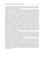
configuration is made as in the previous section. Fig. 7 shows the architecture of a CLDC
configuration with the MID Profile like it is used for mobile applications. Because of the
rapid development and the short life cycle of such devices it is not possible to specify all
variants. Therefore additional native applications, running direct on the operating system,
and manufacturer-specific Java classes and applications are used.
Native
Applications
MIDP Manufacturer-specific Applications
Applications Manufacturer-s. Classes
MIDP
CLDC with KVM
Operation System
Hardware
Fig. 7. Architecture of the CLDC
The following table shows an overview of at present available configurations of Java ME.
Regarding to the technological development of the mobile devices with the CLDC 1.1
compared to its previous version 1.0 the minimum necessary memory was increased from
160 to 192 KB. The main reason for it was the introduction of the classes Float and Double.
Further smaller errors were corrected and some additional classes were added. It might be
only a question of time until all mobile devices support version 1.1 of the configuration, but
at the moment one has to consider which version the current hardware supports.
JSR 30
CLDC 1.0 Connected Limited Device Configuration
JSR 139
CLDC 1.1 Connected Limited Device Configuration 1.1
JSR 36
CDC 1.0 Connected Device Configuration 1.0
JSR 218
CDC 1.1 Connected Device Configuration 1.1
Table 2. Java ME Configurations
The CDC configuration contains a substantially larger part of the Standard Edition APIs.
And the appropriate Foundation Profile contains the entire Java Abstract Window Toolkit
(AWT) with all functions necessary for executing Java Applets. The Personal Basis Profile is
a subset of the Personal Profile and makes available nuclear functionality with a minimum
graphic support. Here is not dealt with CDC and their profiles, since for the for the mobile
application development the CLDC is crucial.
JSR 37
MIDP 1.0 Mobile Information Device Profile
JSR 118
MIDP 2.0 Mobile Information Device Profile 2.0
JSR 75
PDA PDA Profile
JSR 46
FP Foundation Profile
JSR 129
PBP Personal Basis Profile
JSR 62
PP Personal Profile
Table 3. Java ME Profiles
The MIDP bases on the CLDC and contains many important functions like for example
network connections and their protocols, generation of sounds and user interfaces such as
screen or keyboard. The Mobile Information Device Profile specifies also a set of minimal
requirements to the hardware like for example a screen resolution of 96x54 pixels. Today the
version 2.0 is supported by most mobile devices; an overview of the available Java ME
profiles gives the above table.
The optional packages can be merged depending upon the needs of the application and the
hardware requirements. Following table shows an excerpt of the most important Packages
MobileandWirelessCommunications:Networklayerandcircuitleveldesign82
with their JSRs numbers. All JSRs can be looked up under www.jcp.org the homepage of the
Java Community Process, under the direction of Sun.
JSR 75
PIM PDA Optional Packages (PIM und Dateisystem)
JSR 82
BTAPI Bluetooth APIs
JSR 120
WMA Wireless Messaging API
JSR 135
MMAPI Mobile Media API
JSR 172
Web Services
JSR 177
SATSA Security and Trust Services API
JSR 179
Location API
JSR 180
SIP API
JSR 184
Mobile 3D Graphics API
JSR 205
Messaging
JSR 211
Content Handler
JSR 226
Vector Graphics
JSR 229
Payment
JSR 234
Multimedia Supplements
JSR 238
Internationalization
Table 4. Optional Packages
Following table gives an overview of the spreading specifications. The Mobile Service
Architecture specification (MSA) JSR 248 refers like its predecessor JSR 185 to a large extent
of already existing specifications. It eliminates ambiguity and gives supplementing data
where it is necessary. A goal of these spreading specifications should be to prevent a
splintering of the individual APIs and give the different hardware manufacturers a
guideline for the smallest common denominator. A device which fulfills the MSA
specification must at least fulfill the MSA Subset, which is a subset of the MSA with
decreased function range. An overview of the function range and the pertinent JSRs of the
MSA and MSA Subset specification give Fig. 8. A minimum requirement to the hardware of
the devices is also defined by the MSA specification. At least 1024 KB of volatile memory, a
screen size of at least 128x128 pixels with a depth of shade of 16 bits. A multiplicity of
further requirements can be inferred from the documentation JSR 248.
JSR 68
Java ME Java ME Plattform Specification
JSR 185
JTWI Java Technology for Wireless Industry
JSR 248
MSA Mobile Service Architectur
Table 5. Package Bundles
JSR 238 Internationalization
MSA
JSR 234 MultimediaSupplements
JSR 229 Payment
JSR 211 Content Handler
JSR 180 SIP
JSR 179 Location
JSR 177 Security & Trust
JSR 172 Web Services
JSR 226 Vector Graphics
MSA Subset
JSR 205 Messaging
JSR 184 3D Graphics
JSR 135 Mobile Media
JSR 82 Bluetooth
JSR 75 File & PIM
JSR 118 MIDP 2.0
JSR 139 CLDC 1.1
Fig. 8. MSA and MSA Subset
4.2 JSR 82
The JSR 82 (JCP, 2008) was initiated by the JCP, for the development of Bluetooth based
applications of communications and consists of the Java APIs for Bluetooth Wireless
Technology (JABWT). This JSR represents no implementation of the general Bluetooth
specification, but represents a collection of APIs for the configuration and controlling of the
Bluetooth hardware in mobile devices.
The following subsections give beside the requirements of such a device and the structure of
API architecture, views into the necessary configuration of services and devices and the
general operational sequence of Java ME based Bluetooth communication under
consideration of all security aspects.
Requirements:
For the employment of the JSR 82 API on mobile devices at least 512 KB main memory are
needed, as well as a complete implementation of the Java ME CLDC version 1.0. In addition
the existing Bluetooth hardware must exhibit a qualification of the Bluetooth Qualification
Program at least for the profiles GAP, SDAP and SPP. Further the SDP, RFCOMM and the
L2CAP profiles must be supported and accessibility for the API of these protocol layers
must exist.
The access on the lower hardware and protocol layers is administered of a so-called
Bluetooth Control Centre (BCC). Therefore it is not a component of the API, and must be
provided by the hardware environment.
If all requirements are fulfilled, the Bluetooth API offers the following features during the
application development:
- Registration of services
- Inquiry search of Bluetooth hardware and services
- RFCOMM, L2CAP and OBEX connections between Bluetooth devices
WirelessinFutureAutomotiveApplications 83
with their JSRs numbers. All JSRs can be looked up under www.jcp.org the homepage of the
Java Community Process, under the direction of Sun.
JSR 75
PIM PDA Optional Packages (PIM und Dateisystem)
JSR 82
BTAPI Bluetooth APIs
JSR 120
WMA Wireless Messaging API
JSR 135
MMAPI Mobile Media API
JSR 172
Web Services
JSR 177
SATSA Security and Trust Services API
JSR 179
Location API
JSR 180
SIP API
JSR 184
Mobile 3D Graphics API
JSR 205
Messaging
JSR 211
Content Handler
JSR 226
Vector Graphics
JSR 229
Payment
JSR 234
Multimedia Supplements
JSR 238
Internationalization
Table 4. Optional Packages
Following table gives an overview of the spreading specifications. The Mobile Service
Architecture specification (MSA) JSR 248 refers like its predecessor JSR 185 to a large extent
of already existing specifications. It eliminates ambiguity and gives supplementing data
where it is necessary. A goal of these spreading specifications should be to prevent a
splintering of the individual APIs and give the different hardware manufacturers a
guideline for the smallest common denominator. A device which fulfills the MSA
specification must at least fulfill the MSA Subset, which is a subset of the MSA with
decreased function range. An overview of the function range and the pertinent JSRs of the
MSA and MSA Subset specification give Fig. 8. A minimum requirement to the hardware of
the devices is also defined by the MSA specification. At least 1024 KB of volatile memory, a
screen size of at least 128x128 pixels with a depth of shade of 16 bits. A multiplicity of
further requirements can be inferred from the documentation JSR 248.
JSR 68
Java ME Java ME Plattform Specification
JSR 185
JTWI Java Technology for Wireless Industry
JSR 248
MSA Mobile Service Architectur
Table 5. Package Bundles
JSR 238 Internationalization
MSA
JSR 234 MultimediaSupplements
JSR 229 Payment
JSR 211 Content Handler
JSR 180 SIP
JSR 179 Location
JSR 177 Security & Trust
JSR 172 Web Services
JSR 226 Vector Graphics
MSA Subset
JSR 205 Messaging
JSR 184 3D Graphics
JSR 135 Mobile Media
JSR 82 Bluetooth
JSR 75 File & PIM
JSR 118 MIDP 2.0
JSR 139 CLDC 1.1
Fig. 8. MSA and MSA Subset
4.2 JSR 82
The JSR 82 (JCP, 2008) was initiated by the JCP, for the development of Bluetooth based
applications of communications and consists of the Java APIs for Bluetooth Wireless
Technology (JABWT). This JSR represents no implementation of the general Bluetooth
specification, but represents a collection of APIs for the configuration and controlling of the
Bluetooth hardware in mobile devices.
The following subsections give beside the requirements of such a device and the structure of
API architecture, views into the necessary configuration of services and devices and the
general operational sequence of Java ME based Bluetooth communication under
consideration of all security aspects.
Requirements:
For the employment of the JSR 82 API on mobile devices at least 512 KB main memory are
needed, as well as a complete implementation of the Java ME CLDC version 1.0. In addition
the existing Bluetooth hardware must exhibit a qualification of the Bluetooth Qualification
Program at least for the profiles GAP, SDAP and SPP. Further the SDP, RFCOMM and the
L2CAP profiles must be supported and accessibility for the API of these protocol layers
must exist.
The access on the lower hardware and protocol layers is administered of a so-called
Bluetooth Control Centre (BCC). Therefore it is not a component of the API, and must be
provided by the hardware environment.
If all requirements are fulfilled, the Bluetooth API offers the following features during the
application development:
- Registration of services
- Inquiry search of Bluetooth hardware and services
- RFCOMM, L2CAP and OBEX connections between Bluetooth devices
MobileandWirelessCommunications:Networklayerandcircuitleveldesign84
- Transmission of data, excluded voice connections
- Administration and controlling of communication connections
- Security mechanisms for expiration of communication
Here it is pointed out that the presence of Bluetooth and Java on mobile devices does not
guarantee the support of the JSR 82 API, since among other things the possibilities of a
device configuration are reduced by the Java ME. However this applies only to a part of the
mobile phones offered nowadays.
Structure of API architecture:
The JABWT APIs extends the MIDP 2.0 platform with Bluetooth and OBEX support and
consists of two packages, the fundamental Bluetooth API javax.bluetooth and the
OBEX API javax.obex. Both are dependent on the package javax.microedition.io, which
belongs to the CLDC, and optionally applicable depending upon requirements of the
application. Fig. 9 clarifies the position of the Bluetooth API within an CLDC MIDP
environment.
Fig. 9. Bluetooth in the Java Architecture
A Bluetooth application can be divided first into five ranges, which are processed with an
implementation in chronological order: Stack initialization, management of devices, finding
devices, finding services and communication. All APIs needed for these are part of the
javax.bluetooth package.
As was already described on the basis the SDP, Bluetooth devices can take the role of a
server or a client. This is specified in each case by the application. The activity diagram from
following Fig. 10 gives an overview of the individual fields of server and client.
Fig. 10. Client and Server Activities
The initialization of the Bluetooth stack is independently of their operational area necessary
for each Bluetooth application. A client application contains the search for devices and
services, as well as the connection establishment with devices resulting from it and a
following service use. A server application makes services available, administers these and
reacts on connecting inquiries.
4.3 JSR 120 and JSR 205
A further Java API for the mobile communication is the Wireless Messaging API (WMA).
The versions 1.0 and 1.1 were published in the JSR 120 (JCP, 2003) version 2.0 in the JSR 205
(JCP, 2004). With the Wireless Messaging API a mobile application can react on SMS and
MMS messages, which are addressed to a certain port of the mobile phone, to which the
application has registered itself, and process the received data. Messages also SMS in a
binary format can be processed beside simple text or multimedia messages.
For further data communication in mobile communication networks as for example GPRS or
UMTS further APIs are not necessary, since it concerns packet-oriented networks here and
WirelessinFutureAutomotiveApplications 85
- Transmission of data, excluded voice connections
- Administration and controlling of communication connections
- Security mechanisms for expiration of communication
Here it is pointed out that the presence of Bluetooth and Java on mobile devices does not
guarantee the support of the JSR 82 API, since among other things the possibilities of a
device configuration are reduced by the Java ME. However this applies only to a part of the
mobile phones offered nowadays.
Structure of API architecture:
The JABWT APIs extends the MIDP 2.0 platform with Bluetooth and OBEX support and
consists of two packages, the fundamental Bluetooth API javax.bluetooth and the
OBEX API javax.obex. Both are dependent on the package javax.microedition.io, which
belongs to the CLDC, and optionally applicable depending upon requirements of the
application. Fig. 9 clarifies the position of the Bluetooth API within an CLDC MIDP
environment.
Fig. 9. Bluetooth in the Java Architecture
A Bluetooth application can be divided first into five ranges, which are processed with an
implementation in chronological order: Stack initialization, management of devices, finding
devices, finding services and communication. All APIs needed for these are part of the
javax.bluetooth package.
As was already described on the basis the SDP, Bluetooth devices can take the role of a
server or a client. This is specified in each case by the application. The activity diagram from
following Fig. 10 gives an overview of the individual fields of server and client.
Fig. 10. Client and Server Activities
The initialization of the Bluetooth stack is independently of their operational area necessary
for each Bluetooth application. A client application contains the search for devices and
services, as well as the connection establishment with devices resulting from it and a
following service use. A server application makes services available, administers these and
reacts on connecting inquiries.
4.3 JSR 120 and JSR 205
A further Java API for the mobile communication is the Wireless Messaging API (WMA).
The versions 1.0 and 1.1 were published in the JSR 120 (JCP, 2003) version 2.0 in the JSR 205
(JCP, 2004). With the Wireless Messaging API a mobile application can react on SMS and
MMS messages, which are addressed to a certain port of the mobile phone, to which the
application has registered itself, and process the received data. Messages also SMS in a
binary format can be processed beside simple text or multimedia messages.
For further data communication in mobile communication networks as for example GPRS or
UMTS further APIs are not necessary, since it concerns packet-oriented networks here and
MobileandWirelessCommunications:Networklayerandcircuitleveldesign86
so each mobile phone is IP addressable. The operating system usually makes this connection
and administers it. From application view the standard APIs for Socket or HTTP
communication can be used. It is the same procedure like in WLAN networks.
4.4 MIDlet
A Java program which was written for the MID profile is called to MIDlet; one or more
MIDlets can be combined in a MIDlet Suite. After compiling source code one has a jad and a
jar file, which can be loaded on a mobile phone afterwards. Each device on which a MIDlet
should be executed must provide an environment which guarantees execution and
administration of MIDlets. This environment is called Application Management Software
(AMS) and controls the life cycle of the MIDlets. A MIDlet can be like the well-known Java
Applet also only in one of three states. Between the two states Paused and Active the MIDlet
can change during its runtime. The state Destroyed is however final. The MIDlet can even
change its states by the help of special methods, but must notify the AMS about it. The AMS
can change the states of the MIDlets at any time. This can happen if the resources of the
MIDlets are needed by other processes, for example in case of a incoming telephone call the
AMS sets the MIDlet into state Paused and the necessary display is used for the telephone
call.
The MIDlet object is generated by the AMS and is first in the state Paused see Fig. 11, thus
still no resources are blocked. Afterwards the MIDlet is started by the AMS through a call of
the method startApp(). Now the MIDlet is in state Active and all needed resources will
be requested. From the state Active the MIDlet can change again into the state Paused
through the AMS or by itself. If for example a telephone call arrives the AMS sets the MIDlet
into state Paused, since it needs some resources like for example the display of the MIDlet.
The MIDlet asks periodically with the method resumeRequest() if it is allowed to run
again, in this case the AMS starts the MIDlet by means of the method startApp().
Fig. 11. State diagram of a MIDlet
From the state Active the MIDlet can be set by itself or by the AMS into state Destroyed. It
releases then all requested resources and stores if necessary application data for the further
use. Afterwards the MIDlet can be eliminated by the Garbage Collector.
4.5 Application Deployment
The occasionally complex installation was a big obstacle in the past which prevented a wide
spreading of mobile applications. Usually for this a PC with for the mobile phone suitable
configuration software was necessary, with which the mobile phone was connected by a
data cable. For mobile Java applications there is another further alternative, which is favored
in particular by the mobile games market. Here the installation of new MIDlets is at any
time at each place within shortest time possible, always when the user needs certain
programs for its mobile phone. This is reached by the download of the desired MIDlet over
a UMTS or a GPRS connection. The necessary URL for this receives the user either from the
browser of the mobile phone or by SMS. In addition such a call is also directly possible from
a MIDlet. The development of specialized Part-MIDlets, for example for different equipment
variants of a vehicle, is now possible which are downloaded on demand directly to the
user's mobile phone.
The protocol for such a Over The Air (OTA) transmission is HTTP. Communication over
HTTP is a firm component of MIDP and thus the standard technique for the data
communication of MIDlets. The support of further protocols is however optional. In
addition MIDlets offer with the method platformRequest(string URL) a standard
procedure for the download of new programs over a HTTP connection.
Apart from the MIDP specification the optional content Handler API (JSR 211) contains also
this functionality. Duty of the content Handler API is actually to pass certain tasks to other
programs. For example playing music at the on the mobile phone installed media player.
However it can be also used to download and to install new programs on the device.
With this kind of installation the appropriate jad and jar file must be on a web server
reachable for the mobile device. In the jad file thereby to the location of the jar file is
referred.
4.6 Security
In MIDP there is an extensive security concept, which on the public key procedure for the
verification and authentication of MIDlet Suites is based. This security concept serves the
preventing of, the use of sensitive operations, like for example the establishment of a
expensive network connection, without preventing the knowledge of the user. So that a
signed MIDlet can get access to a sensitive API, the appropriate permission must be set. This
permission is indicated in the jad file.
In MIDP there are so-called Protection Domains which MIDlets are assigned to. In the
Protection Domains is specified how to deal with the permissions.
There are the following Protection Domains:
minimum: MIDlets of these Protection Domain, access to all Permissions is refused.
untrusted: The user must give his agreement with each call to an API proteceted by a
Permission of these Protection Domain. This is the default domain for unsigned MIDlets.
trusted/maximum: The access to all Permissions of this Protection Domain is permitted.
WirelessinFutureAutomotiveApplications 87
so each mobile phone is IP addressable. The operating system usually makes this connection
and administers it. From application view the standard APIs for Socket or HTTP
communication can be used. It is the same procedure like in WLAN networks.
4.4 MIDlet
A Java program which was written for the MID profile is called to MIDlet; one or more
MIDlets can be combined in a MIDlet Suite. After compiling source code one has a jad and a
jar file, which can be loaded on a mobile phone afterwards. Each device on which a MIDlet
should be executed must provide an environment which guarantees execution and
administration of MIDlets. This environment is called Application Management Software
(AMS) and controls the life cycle of the MIDlets. A MIDlet can be like the well-known Java
Applet also only in one of three states. Between the two states Paused and Active the MIDlet
can change during its runtime. The state Destroyed is however final. The MIDlet can even
change its states by the help of special methods, but must notify the AMS about it. The AMS
can change the states of the MIDlets at any time. This can happen if the resources of the
MIDlets are needed by other processes, for example in case of a incoming telephone call the
AMS sets the MIDlet into state Paused and the necessary display is used for the telephone
call.
The MIDlet object is generated by the AMS and is first in the state Paused see Fig. 11, thus
still no resources are blocked. Afterwards the MIDlet is started by the AMS through a call of
the method startApp(). Now the MIDlet is in state Active and all needed resources will
be requested. From the state Active the MIDlet can change again into the state Paused
through the AMS or by itself. If for example a telephone call arrives the AMS sets the MIDlet
into state Paused, since it needs some resources like for example the display of the MIDlet.
The MIDlet asks periodically with the method resumeRequest() if it is allowed to run
again, in this case the AMS starts the MIDlet by means of the method startApp().
Fig. 11. State diagram of a MIDlet
From the state Active the MIDlet can be set by itself or by the AMS into state Destroyed. It
releases then all requested resources and stores if necessary application data for the further
use. Afterwards the MIDlet can be eliminated by the Garbage Collector.
4.5 Application Deployment
The occasionally complex installation was a big obstacle in the past which prevented a wide
spreading of mobile applications. Usually for this a PC with for the mobile phone suitable
configuration software was necessary, with which the mobile phone was connected by a
data cable. For mobile Java applications there is another further alternative, which is favored
in particular by the mobile games market. Here the installation of new MIDlets is at any
time at each place within shortest time possible, always when the user needs certain
programs for its mobile phone. This is reached by the download of the desired MIDlet over
a UMTS or a GPRS connection. The necessary URL for this receives the user either from the
browser of the mobile phone or by SMS. In addition such a call is also directly possible from
a MIDlet. The development of specialized Part-MIDlets, for example for different equipment
variants of a vehicle, is now possible which are downloaded on demand directly to the
user's mobile phone.
The protocol for such a Over The Air (OTA) transmission is HTTP. Communication over
HTTP is a firm component of MIDP and thus the standard technique for the data
communication of MIDlets. The support of further protocols is however optional. In
addition MIDlets offer with the method platformRequest(string URL) a standard
procedure for the download of new programs over a HTTP connection.
Apart from the MIDP specification the optional content Handler API (JSR 211) contains also
this functionality. Duty of the content Handler API is actually to pass certain tasks to other
programs. For example playing music at the on the mobile phone installed media player.
However it can be also used to download and to install new programs on the device.
With this kind of installation the appropriate jad and jar file must be on a web server
reachable for the mobile device. In the jad file thereby to the location of the jar file is
referred.
4.6 Security
In MIDP there is an extensive security concept, which on the public key procedure for the
verification and authentication of MIDlet Suites is based. This security concept serves the
preventing of, the use of sensitive operations, like for example the establishment of a
expensive network connection, without preventing the knowledge of the user. So that a
signed MIDlet can get access to a sensitive API, the appropriate permission must be set. This
permission is indicated in the jad file.
In MIDP there are so-called Protection Domains which MIDlets are assigned to. In the
Protection Domains is specified how to deal with the permissions.
There are the following Protection Domains:
minimum: MIDlets of these Protection Domain, access to all Permissions is refused.
untrusted: The user must give his agreement with each call to an API proteceted by a
Permission of these Protection Domain. This is the default domain for unsigned MIDlets.
trusted/maximum: The access to all Permissions of this Protection Domain is permitted.
MobileandWirelessCommunications:Networklayerandcircuitleveldesign88
One frequently still differentiates with trusted Protection Domains according to the
certification authority:
manufacturer: Uses certificates of the device manufacturer.
operator: Uses certificates of the network provider.
trusted third party: Uses third party certificates.
With the permissions two types are differentiated:
allowed: The access is permitted without demand of the user.
user: The user must give his agreement for the call of the associated API.
With user Permissions between the following types one differentiates:
oneshot: Inquire with each call.
session: Once inquire, decision remains valid as long as MIDlets of these MIDlet Suite are
active.
blanket: Once inquired, decision remains valid as long as the MIDlet Suite is installed.
If a MIDlet is in the trusted Protection Domain and the type of Permission is allowed, then it
can use the associated API without demand of the user.
To which Protection Domain a MIDlet Suite belongs depends on the root certificate existing
on the devices. With the installation the signature of the MIDlets is compared with the
existing root certificates and accordingly a classification is made.
5. Vehicle integration
Cars are usually products, which come from one hand, from the car manufacturer. The
offerers of accessory components so-called off board devices have a not insignificant
problem, since usually no standard interfaces for the integration of these devices are present
or must be licensed by the vehicle manufacturer. But even if such a license and the necessary
installation interfaces are present, still the problem of the user interface remains for the
offerer of accessory components. These are frequently goods in short supply and reserved
for the OEM (Original Equipment Manufacturer) in the vehicle. From there the accessory
offerers mostly offer their own control elements, which are expenditure-stuck or stuck on
the instrument panel. Apart from the optical lack that control elements does not fit the
design and cables lay partly openly, remains the problem, that these control elements do not
fit into the control concept of the vehicle.
There is however one off board device, which is accepted by practically all car
manufacturers and for both, interfaces for the integration in the vehicle and a firm place in
the instrument panel is present. In addition it is suitable outstanding as universal control
element for a multiplicity of devices. Meant here is the mobile phone.
Mobile phones are suitable on the one hand so well, because they possess many
communication interfaces, beside the mandatory GSM, GPRS, UMTS support they
frequently have Bluetooth and some models even WLAN interfaces. The employment of
wireless technologies makes besides the cable to the control elements redundantly. The
suitable communication technology can be selected depending upon application. For
vehicle-internal communication a short range technology is sufficient as for example
Bluetooth. However even if a genuine remote maintenance is to be realized over far
distances a UMTS or a GPRS connection offers itself for this.
On the other hand mobile phones can be programmed almost at will, so that control
applications for the most diverse devices can be realized. The advantages of the Java Micro
edition in this area were stated already in detail.
5.1 Example auxiliary heating
How the integration into a vehicle is in detail realized is to be described in the following by
the example of a auxiliary heating. The auxiliary heating is installed in the vehicle and
attached to the CAN (Controller Area Network) bus of the car, over which all controllers are
interlaced and receive their instructions. The instructions come of one at the instrument
panel fastened or into it inserted, control element which is likewise connected with the CAN
bus. Instead of this control element or also as addition of it now a mobile phone is to be
used.
In principle for this UMTS/GPRS and Bluetooth present themselves as communication
technology. Bluetooth for communication within the car and UMTS/GPRS for the remote
maintenance from the domestic living room. Since the integration is very similar in both
cases and Bluetooth besides brings the standardized communication profiles with it,
contains the following example for the sake of simplicity only to Bluetooth. Following Fig.
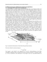
12 outlines the fundamental structure of such a system.
WirelessinFutureAutomotiveApplications 89
One frequently still differentiates with trusted Protection Domains according to the
certification authority:
manufacturer: Uses certificates of the device manufacturer.
operator: Uses certificates of the network provider.
trusted third party: Uses third party certificates.
With the permissions two types are differentiated:
allowed: The access is permitted without demand of the user.
user: The user must give his agreement for the call of the associated API.
With user Permissions between the following types one differentiates:
oneshot: Inquire with each call.
session: Once inquire, decision remains valid as long as MIDlets of these MIDlet Suite are
active.
blanket: Once inquired, decision remains valid as long as the MIDlet Suite is installed.
If a MIDlet is in the trusted Protection Domain and the type of Permission is allowed, then it
can use the associated API without demand of the user.
To which Protection Domain a MIDlet Suite belongs depends on the root certificate existing
on the devices. With the installation the signature of the MIDlets is compared with the
existing root certificates and accordingly a classification is made.
5. Vehicle integration
Cars are usually products, which come from one hand, from the car manufacturer. The
offerers of accessory components so-called off board devices have a not insignificant
problem, since usually no standard interfaces for the integration of these devices are present
or must be licensed by the vehicle manufacturer. But even if such a license and the necessary
installation interfaces are present, still the problem of the user interface remains for the
offerer of accessory components. These are frequently goods in short supply and reserved
for the OEM (Original Equipment Manufacturer) in the vehicle. From there the accessory
offerers mostly offer their own control elements, which are expenditure-stuck or stuck on
the instrument panel. Apart from the optical lack that control elements does not fit the
design and cables lay partly openly, remains the problem, that these control elements do not
fit into the control concept of the vehicle.
There is however one off board device, which is accepted by practically all car
manufacturers and for both, interfaces for the integration in the vehicle and a firm place in
the instrument panel is present. In addition it is suitable outstanding as universal control
element for a multiplicity of devices. Meant here is the mobile phone.
Mobile phones are suitable on the one hand so well, because they possess many
communication interfaces, beside the mandatory GSM, GPRS, UMTS support they
frequently have Bluetooth and some models even WLAN interfaces. The employment of
wireless technologies makes besides the cable to the control elements redundantly. The
suitable communication technology can be selected depending upon application. For
vehicle-internal communication a short range technology is sufficient as for example
Bluetooth. However even if a genuine remote maintenance is to be realized over far
distances a UMTS or a GPRS connection offers itself for this.
On the other hand mobile phones can be programmed almost at will, so that control
applications for the most diverse devices can be realized. The advantages of the Java Micro
edition in this area were stated already in detail.
5.1 Example auxiliary heating
How the integration into a vehicle is in detail realized is to be described in the following by
the example of a auxiliary heating. The auxiliary heating is installed in the vehicle and
attached to the CAN (Controller Area Network) bus of the car, over which all controllers are
interlaced and receive their instructions. The instructions come of one at the instrument
panel fastened or into it inserted, control element which is likewise connected with the CAN
bus. Instead of this control element or also as addition of it now a mobile phone is to be
used.
In principle for this UMTS/GPRS and Bluetooth present themselves as communication
technology. Bluetooth for communication within the car and UMTS/GPRS for the remote
maintenance from the domestic living room. Since the integration is very similar in both
cases and Bluetooth besides brings the standardized communication profiles with it,
contains the following example for the sake of simplicity only to Bluetooth. Following Fig.
12 outlines the fundamental structure of such a system.
MobileandWirelessCommunications:Networklayerandcircuitleveldesign90
Fig. 12. Vehicle integration
The auxiliary heating and its control elements communicate no longer directly over CAN
bus with each another, but over an interface or a gateway. The gateway controls the data
transfer in the vehicle and passes the data on to the respective control devices. In the
concrete example the gateway has a Bluetooth SPP connection to the mobile phone, over
that it transfers the instructions of the remote control unit.
On the mobile phone a Java MIDlet runs, which the user downloaded ideally-proved
directly from the Web server of the auxiliary heating manufacturer and installed it
afterwards on his device. Security is ensured thereby by an appropriate signature of the
MIDlets, which regalements the access to resources of the mobile phone e.g. communication
interfaces and memory.
Even the selection of a suitable MIDlet for the vehicle-auxiliary-heating-mobile-phone-
combination can be automated to a large extent, if device type and Bluetooth address of the
user are deposited on a central server. This is can be done by a service technician for
example with the installation.
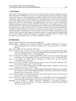
The scenario to the deployment of the application has the following in Fig. 13 described
expiration.
Fig. 13. Automatic Application Deployment
After the auxiliary heating was installed in the vehicle and the service technician has
deposited the Bluetooth address, the telephone number and the type of device on the server
starts the scenario.
1. The vehicle starts a search for Bluetooth devices in the environment. It acts around a
functionality of the Bluetooth standard.
2. The found devices convey their Bluetooth address for later identification.
3. A list of the found devices is sent over a GPRS/UMTS connection to the server.
4. The server examined on the basis the Bluetooth addresses whether it for one of the found
devices an order has, and selects on the basis the deposited type information a MIDlet
fitting to the device type.
5. The server sends a SMS with the appropriate download link to mobile phone.
Subsequently, the user opens the link and downloads the MIDlet to his mobile phone.
6. Subsequently, automatically the installation procedure begins. The user now only has to
agree with the installation.
WirelessinFutureAutomotiveApplications 91
Fig. 12. Vehicle integration
The auxiliary heating and its control elements communicate no longer directly over CAN
bus with each another, but over an interface or a gateway. The gateway controls the data
transfer in the vehicle and passes the data on to the respective control devices. In the
concrete example the gateway has a Bluetooth SPP connection to the mobile phone, over
that it transfers the instructions of the remote control unit.
On the mobile phone a Java MIDlet runs, which the user downloaded ideally-proved
directly from the Web server of the auxiliary heating manufacturer and installed it
afterwards on his device. Security is ensured thereby by an appropriate signature of the
MIDlets, which regalements the access to resources of the mobile phone e.g. communication
interfaces and memory.
Even the selection of a suitable MIDlet for the vehicle-auxiliary-heating-mobile-phone-
combination can be automated to a large extent, if device type and Bluetooth address of the
user are deposited on a central server. This is can be done by a service technician for
example with the installation.
The scenario to the deployment of the application has the following in Fig. 13 described
expiration.
Fig. 13. Automatic Application Deployment
After the auxiliary heating was installed in the vehicle and the service technician has
deposited the Bluetooth address, the telephone number and the type of device on the server
starts the scenario.
1. The vehicle starts a search for Bluetooth devices in the environment. It acts around a
functionality of the Bluetooth standard.
2. The found devices convey their Bluetooth address for later identification.
3. A list of the found devices is sent over a GPRS/UMTS connection to the server.
4. The server examined on the basis the Bluetooth addresses whether it for one of the found
devices an order has, and selects on the basis the deposited type information a MIDlet
fitting to the device type.
5. The server sends a SMS with the appropriate download link to mobile phone.
Subsequently, the user opens the link and downloads the MIDlet to his mobile phone.
6. Subsequently, automatically the installation procedure begins. The user now only has to
agree with the installation.
MobileandWirelessCommunications:Networklayerandcircuitleveldesign92
7. After finishing the installation the MIDlet is started directly and can be connected by
Bluetooth with the auxiliary heating, in dependence of its signature. The application is
ready for use thereby and the user can control his auxiliary heating.
6. Conclusion
The chapter showed that wireless communication already belongs in many areas of the
automotive environment to the state of the art. Straight development possibilities further
with the integration of mobile phones are present nevertheless. Bluetooth presents itself here
as almost ideal communication technology for many applications.
For the development of mobile phone applications the Java Micro Edition is first choice, it
offers not only large platform independence, but also detailed concepts to the deployment of
applications or for security. In addition APIs are available for all usual communication
technologies.
The mobile phone is the only off board device accepted by car manufacturers. That makes it
interesting for the manufacturers of accessory components to use these as control elements.
A concept for this was explained in the chapter.
7. References
Bluetooth SIG (2009). www.bluetooth.org
Breymann, U. & Mosemann H. (2008). Java ME. Anwendungsentwicklung für Handys, PDA und
Co (Germann), Hanser, 3446229973, Munich
JCP (2008). />
JCP (2003).
JCP (2004). />
IEEE (2002).
Sun Microsystems (2009). />
PassiveWirelessDevicesUsingExtremelyLowtoHighFrequencyLoadModulation 93
PassiveWirelessDevicesUsingExtremelyLowtoHighFrequencyLoad
Modulation
HubertZangl,MichaelJ.Moser,ThomasBretterklieberandAntonFuchs
0
Passive Wireless Devices Using Extremely
Low to High Frequency Load Modulation
Hubert Zangl, Michael J. Moser, Thomas Bretterklieber, and Anton Fuchs
Institute of Electrical Measurement and Measurement Signal Processing,
Graz University of Technology, Kronesgasse 5, A-8010 Graz
Austria
1. Introduction
Whereas passive wireless communication in the Ultra High Frequency (UHF) domain features
long ranges of several meters in free space, systems utilizing lower frequencies in the ELF
(Extremely Low Frequency) to HF (High Frequency) domain can be advantageous in environ-
ments with conductive materials or where large antennas are not prohibitive. Additionally,
the operation range is well defined and can be practically restricted to several centimeters like
in Near Field Communication (NFC) Standard ECMA-340 Near Field Communication Interface
and Protocol (NFCIP-2) (2003), although this does not necessarily mean that communication is
secure Hancke (2008).
In this chapter we investigate passive wireless devices in the frequency range from almost
DC to tens of Megahertz, i.e. from the ELF to the HF domain. Common abbreviations for
the ITU frequency ranges are summarized in Table 1. The most common Radio Frequency
Identification (RFID) systems use the LF (@125 kHz) and the HF (@13.56 MHz) bands. This
chapter also considers lower frequencies.
Abbreviation Range Name
subHz < 3 Hz SubHertz
ELF 3 Hz - 30 Hz Extremely Low Frequency
SLF 20 Hz - 300 Hz Super Low Frequency
ULF 0.3 kHz-3 kHz Ultra Low Frequency
VLF 3 kHz - 30 kHz Very Low Frequency
LF 30 kHz - 300 kHz Low Frequency
MF 300 kHz - 3 MHz Medium Frequency
HF 3 MHz - 30 MHz High Frequency
VHF 30 MHz - 300 MHz Very High Frequency
UHF 300 MHz - 3 GHz Ultra High Frequency
This Chapter
Table 1. ITU frequency ranges and abbreviations.
We provide a brief introduction to the technology, performance estimations in terms of pow-
ering range with respect to permitted signal levels and human exposure issues, performance
considerations in terms of data transmission range with respect to background and man-made
noise, and analysis of the impact of conductive/dielectric materials in the vicinity of the pas-
sive wireless devices (transponders).
6
MobileandWirelessCommunications:Networklayerandcircuitleveldesign94
We provide an introduction to the concept of load modulation techniques for passive wireless
communication. Usually, RFID systems in the low to high frequency range (LF to HF) are
considered as loosely inductively coupled transformers.
The basic principle of such mainly inductively coupled systems is shown in Figure 1. A pri-
mary coil of the reader generates an alternating magnetic field and induces a voltage in the
coil antenna of the wireless device. The primary coil is connected to a diplexer that carries
out frequency separation between the power supply path and the data path. The alternat-
ing magnetic field may penetrate layers of air, liquids (e.g. water) or layers of stainless steel
and other weak conductors and will then induce a voltage in the coil antenna of the wireless
device. A tuning element (e.g. a capacitor) and a power harvesting and storage unit (mainly
comprising a rectifier and a storage capacitor) are needed to power the electronic components.
A demodulator can extract data sent from the ”reader”. The transponder itself can transmit
data by means of load modulation. This is, e.g., performed by a logic-controlled switch that
changes the load of the secondary coil. The control logic can read out a sensor (e.g. a change
in resistance or capacitance of a temperature or pressure sensor) and transmit this data back
to the reader.
Reader
Transponder
Airand/ormetal
Power
Harvesting
Load
Modulation
Tuning
Demodulator
ControlLogic
Sensor
Diplexer
DataI/O
Power
Supply
Fig. 1. Principle of passive wireless reader-transponder pair in the ELF to HF bands.
2. Application Examples
Various fields of application can be thought of for passive wireless devices in or behind metal
housings powered by low frequent magnetic fields. In this section, we present example appli-
cations.
Transmitting measurement data through a double-walled stainless steel vessel can be neces-
sary when extreme temperatures, high pressures, or other harsh environmental conditions
(e.g. hazardous substances) are present. This could be a thermally insulated liquid hydrogen
storage tank in a car, a whipped cream maker or a chemical reactor. Figure 2(a) shows a sim-
plified block diagram of a setup. Figure 2(b) shows an example experimental setup using a
whipped cream maker. The corresponding transponder is immersed in the liquid inside the
vessel.
Another interesting application is e.g. for magnetic stirrers, which are standard devices in
chemical laboratories. Equipping the magnetic stirring bar (a bar magnet with a protective
coating made from either PTFE or stainless steel) with a miniaturized RFID tag that supplies
a sensor interface, one could sense and display process parameters directly from the fluid
that is stirred and thereby merge multiple devices (e.g. magnetic stirrer, temperature sensor,
pH sensor) to a single device, which may need less space and reduce total equipment costs.
Reader
Transponderindouble-walledstainlesssteelhousing
Airand/orliquid
Power
Harvesting
Load
Modulation
Tuning
Demodulator
ControlLogic
Sensor
Diplexer
DataI/O
Power
Supply
(a) (b)
Fig. 2. (a) Schematic of a measurement setup for transmitting measurement data (e.g. pres-
sure or temperature) through a double-walled stainless steel vessel. (b) Photo of an example
measurement setup for transmitting temperature data (also other quantities such as pressure
could be measured) through a thermally insulated double-walled stainless steel vessel. Here,
the passive transponder is placed in a whipped cream maker and could be used, e.g., to mon-
itor the temperature of the liquid.
Figure 3(a) depicts the schematic of such a setup, Figure 3(b) shows an example laboratory
setup.
Figure 3(a) depicts the schematic of such a setup, Figure 3(b) shows an example laboratory
setup
3. Comparison of Frequency Ranges from ELF to LF
The power that can be transmitted to wireless electronic devices by means of inductive cou-
pling is rather limited by restrictions of the field strength than by technological limits. E.g.,
power transmissions of up to 60 W have been reported in Kurs et al. (2007). However, in
practice we are faced with limitations of the permitted field strength, due to both electromag-
netic compatibility and human exposure issues. The investigations in this section are based
on the limits provided in ERC Recommendation 70-03: Relating to the use of short range devices
(SRD) (2007) for limits regarding electromagnetic compatibility and ICNIRP (1998) regarding
reference levels with respect to human exposure to alternating magnetic fields for the general
public.
Electronic circuitry usually requires DC operating voltage. Therefore, passive devices require
a rectifier circuit and an energy storage. Both diodes and transistors can be used for the recti-
fier, where transistors often offer the advantage of lower voltage drops. For the operation of
the circuit it is important to achieve a certain minimum voltage. Consequently, the slew rate
of the magnetic field must be high enough. This can be achieved by a high frequency and/or
a high field magnitude.
Figure 4 shows Root Mean Square (RMS) reference levels for head, neck and trunk for the
general public according to ICNIRP (1998). In the frequency range of up to 100 kHz, the peak
values can be
√
2 higher than the RMS values. In the range from 100 kHz to 10 MHz, the
permitted peak values increase to 32 times the RMS limit.
PassiveWirelessDevicesUsingExtremelyLowtoHighFrequencyLoadModulation 95
We provide an introduction to the concept of load modulation techniques for passive wireless
communication. Usually, RFID systems in the low to high frequency range (LF to HF) are
considered as loosely inductively coupled transformers.
The basic principle of such mainly inductively coupled systems is shown in Figure 1. A pri-
mary coil of the reader generates an alternating magnetic field and induces a voltage in the
coil antenna of the wireless device. The primary coil is connected to a diplexer that carries
out frequency separation between the power supply path and the data path. The alternat-
ing magnetic field may penetrate layers of air, liquids (e.g. water) or layers of stainless steel
and other weak conductors and will then induce a voltage in the coil antenna of the wireless
device. A tuning element (e.g. a capacitor) and a power harvesting and storage unit (mainly
comprising a rectifier and a storage capacitor) are needed to power the electronic components.
A demodulator can extract data sent from the ”reader”. The transponder itself can transmit
data by means of load modulation. This is, e.g., performed by a logic-controlled switch that
changes the load of the secondary coil. The control logic can read out a sensor (e.g. a change
in resistance or capacitance of a temperature or pressure sensor) and transmit this data back
to the reader.
Reader
Transponder
Airand/ormetal
Power
Harvesting
Load
Modulation
Tuning
Demodulator
ControlLogic
Sensor
Diplexer
DataI/O
Power
Supply
Fig. 1. Principle of passive wireless reader-transponder pair in the ELF to HF bands.
2. Application Examples
Various fields of application can be thought of for passive wireless devices in or behind metal
housings powered by low frequent magnetic fields. In this section, we present example appli-
cations.
Transmitting measurement data through a double-walled stainless steel vessel can be neces-
sary when extreme temperatures, high pressures, or other harsh environmental conditions
(e.g. hazardous substances) are present. This could be a thermally insulated liquid hydrogen
storage tank in a car, a whipped cream maker or a chemical reactor. Figure 2(a) shows a sim-
plified block diagram of a setup. Figure 2(b) shows an example experimental setup using a
whipped cream maker. The corresponding transponder is immersed in the liquid inside the
vessel.
Another interesting application is e.g. for magnetic stirrers, which are standard devices in
chemical laboratories. Equipping the magnetic stirring bar (a bar magnet with a protective
coating made from either PTFE or stainless steel) with a miniaturized RFID tag that supplies
a sensor interface, one could sense and display process parameters directly from the fluid
that is stirred and thereby merge multiple devices (e.g. magnetic stirrer, temperature sensor,
pH sensor) to a single device, which may need less space and reduce total equipment costs.
Reader
Transponderindouble-walledstainlesssteelhousing
Airand/orliquid
Power
Harvesting
Load
Modulation
Tuning
Demodulator
ControlLogic
Sensor
Diplexer
DataI/O
Power
Supply
(a) (b)
Fig. 2. (a) Schematic of a measurement setup for transmitting measurement data (e.g. pres-
sure or temperature) through a double-walled stainless steel vessel. (b) Photo of an example
measurement setup for transmitting temperature data (also other quantities such as pressure
could be measured) through a thermally insulated double-walled stainless steel vessel. Here,
the passive transponder is placed in a whipped cream maker and could be used, e.g., to mon-
itor the temperature of the liquid.
Figure 3(a) depicts the schematic of such a setup, Figure 3(b) shows an example laboratory
setup.
Figure 3(a) depicts the schematic of such a setup, Figure 3(b) shows an example laboratory
setup
3. Comparison of Frequency Ranges from ELF to LF
The power that can be transmitted to wireless electronic devices by means of inductive cou-
pling is rather limited by restrictions of the field strength than by technological limits. E.g.,
power transmissions of up to 60 W have been reported in Kurs et al. (2007). However, in
practice we are faced with limitations of the permitted field strength, due to both electromag-
netic compatibility and human exposure issues. The investigations in this section are based
on the limits provided in ERC Recommendation 70-03: Relating to the use of short range devices
(SRD) (2007) for limits regarding electromagnetic compatibility and ICNIRP (1998) regarding
reference levels with respect to human exposure to alternating magnetic fields for the general
public.
Electronic circuitry usually requires DC operating voltage. Therefore, passive devices require
a rectifier circuit and an energy storage. Both diodes and transistors can be used for the recti-
fier, where transistors often offer the advantage of lower voltage drops. For the operation of
the circuit it is important to achieve a certain minimum voltage. Consequently, the slew rate
of the magnetic field must be high enough. This can be achieved by a high frequency and/or
a high field magnitude.
Figure 4 shows Root Mean Square (RMS) reference levels for head, neck and trunk for the
general public according to ICNIRP (1998). In the frequency range of up to 100 kHz, the peak
values can be
√
2 higher than the RMS values. In the range from 100 kHz to 10 MHz, the
permitted peak values increase to 32 times the RMS limit.
MobileandWirelessCommunications:Networklayerandcircuitleveldesign96
(a)
Reader
(builtintostirrerdevice)
Sensortransponder
(includedinmagneticstirringbar)
Liquid
Stainlesssteeland/orPTFEhousing
Stainlesssteelhousing
Glassvessel
Power
Harvesting
Load
Modulation
Tuning
Demodulator
ControlLogic
Sensor
Diplexer
DataI/O
Power
Supply
(b)
Fig. 3. (a) Photo of an example measurement setup for transmitting measurement data (e.g.
temperature or pH data) from a sensor built into the magnetic stirring bar. The stirrer device
will be equipped with a suitable readout circuitry and a numeric display. (b) Schematic of a
measurement setup for transmitting measurement data.
An interpretation of these levels with respect to inductive wireless devices is provided in Fig-
ure 5. For a single turn circular loop with a square area of 1 cm
2
, the voltage ranges from about
1 µV to several mV. However, this induced voltage is not sufficient to power an electronic cir-
cuit. With current semiconductor technology, the peak voltage should roughly exceed 1 V for
a circuit to operate. Several techniques that can be used to increase the voltage are summa-
rized in Table 2. The easiest methods are an increase of the area of the transponder antenna
and an increase of the number of turns. Both methods are restricted by size and costs of the
transponder. Resonance gain is also commonly exploited. Here, the antenna inductance L
and an additional capacitor C form a resonance circuit. With this simple circuit, the antenna
current and the voltage across the inductor as well as the capacitor are increased by the qual-
ity factor Q
=
2π f L
R
of the resonance circuit, which means that the coil resistance R must be
low compared to the impedance of the coil inductance at the given frequency f . At lower
frequencies, the resonance condition f
=
1
2π
√
LC
requires high L and/or C values, which may
be difficult to implement. On the other hand, coils with high numbers of windings may have
too low self resonance values due to parasitic capacitances e.g. in the HF range. Another
drawback of high quality factors is the associated low bandwidth. A slight change of the in-
ductance L or the capacitance C will change the resonance frequency of the circuit and the
gain effect is lost. The resonance is also affected when two or more resonance circuits are in
close vicinity. Therefore, in applications where many devices may be present (e.g. in batches
of casino tokens) the quality factor is usually kept low. Further increases of the voltage can be
achieved with electronic components such as diodes, e.g. in voltage multipliers (e.g. Gosset
et al. (2008)) or in active up-conversion. The latter has the drawback that energy is required to
get the up-conversion started (cf. section 3.2.1).
Usually, a combination of several of these techniques is necessary to make the low induced
voltage useful for powering electronic devices. An example for the HF domain is provided in
Figure 7. With several turns, an area of several square centimeters, and a quality factor above
10, the voltage can be sufficient to power the circuitry.
10
−2
10
0
10
2
10
4
10
6
10
8
10
10
10
−2
10
0
10
2
10
4
10
6
Max. Recommended Magnetic Field Strength (General Public)
f [Hz]
H [A/m]
Fig. 4. Reference levels for the magnetic field strength for general public exposure to time
varying fields ICNIRP (1998). These levels are obtained based on the impact (particulary on
head, neck and trunk) of induced currents on the nervous system (up to 10 MHz) and the
temperature increase of tissue due to absorption (above 100 kHz).
10
−2
10
0
10
2
10
4
10
6
10
8
10
10
10
−6
10
−5
10
−4
10
−3
10
−2
10
−1
Voltage per turn and area [V/cm
2
]
f [Hz]
U [V]
Fig. 5. Induced voltage for a single loop coil with an area of 1 cm
2
at the reference levels
according to ICNIRP (1998).
PassiveWirelessDevicesUsingExtremelyLowtoHighFrequencyLoadModulation 97
(a)
Reader
(builtintostirrerdevice)
Sensortransponder
(includedinmagneticstirringbar)
Liquid
Stainlesssteeland/orPTFEhousing
Stainlesssteelhousing
Glassvessel
Power
Harvesting
Load
Modulation
Tuning
Demodulator
ControlLogic
Sensor
Diplexer
DataI/O
Power
Supply
(b)
Fig. 3. (a) Photo of an example measurement setup for transmitting measurement data (e.g.
temperature or pH data) from a sensor built into the magnetic stirring bar. The stirrer device
will be equipped with a suitable readout circuitry and a numeric display. (b) Schematic of a
measurement setup for transmitting measurement data.
An interpretation of these levels with respect to inductive wireless devices is provided in Fig-
ure 5. For a single turn circular loop with a square area of 1 cm
2
, the voltage ranges from about
1 µV to several mV. However, this induced voltage is not sufficient to power an electronic cir-
cuit. With current semiconductor technology, the peak voltage should roughly exceed 1 V for
a circuit to operate. Several techniques that can be used to increase the voltage are summa-
rized in Table 2. The easiest methods are an increase of the area of the transponder antenna
and an increase of the number of turns. Both methods are restricted by size and costs of the
transponder. Resonance gain is also commonly exploited. Here, the antenna inductance L
and an additional capacitor C form a resonance circuit. With this simple circuit, the antenna
current and the voltage across the inductor as well as the capacitor are increased by the qual-
ity factor Q
=
2π f L
R
of the resonance circuit, which means that the coil resistance R must be
low compared to the impedance of the coil inductance at the given frequency f . At lower
frequencies, the resonance condition f
=
1
2π
√
LC
requires high L and/or C values, which may
be difficult to implement. On the other hand, coils with high numbers of windings may have
too low self resonance values due to parasitic capacitances e.g. in the HF range. Another
drawback of high quality factors is the associated low bandwidth. A slight change of the in-
ductance L or the capacitance C will change the resonance frequency of the circuit and the
gain effect is lost. The resonance is also affected when two or more resonance circuits are in
close vicinity. Therefore, in applications where many devices may be present (e.g. in batches
of casino tokens) the quality factor is usually kept low. Further increases of the voltage can be
achieved with electronic components such as diodes, e.g. in voltage multipliers (e.g. Gosset
et al. (2008)) or in active up-conversion. The latter has the drawback that energy is required to
get the up-conversion started (cf. section 3.2.1).
Usually, a combination of several of these techniques is necessary to make the low induced
voltage useful for powering electronic devices. An example for the HF domain is provided in
Figure 7. With several turns, an area of several square centimeters, and a quality factor above
10, the voltage can be sufficient to power the circuitry.
10
−2
10
0
10
2
10
4
10
6
10
8
10
10
10
−2
10
0
10
2
10
4
10
6
Max. Recommended Magnetic Field Strength (General Public)
f [Hz]
H [A/m]
Fig. 4. Reference levels for the magnetic field strength for general public exposure to time
varying fields ICNIRP (1998). These levels are obtained based on the impact (particulary on
head, neck and trunk) of induced currents on the nervous system (up to 10 MHz) and the
temperature increase of tissue due to absorption (above 100 kHz).
10
−2
10
0
10
2
10
4
10
6
10
8
10
10
10
−6
10
−5
10
−4
10
−3
10
−2
10
−1
Voltage per turn and area [V/cm
2
]
f [Hz]
U [V]
Fig. 5. Induced voltage for a single loop coil with an area of 1 cm
2
at the reference levels
according to ICNIRP (1998).
MobileandWirelessCommunications:Networklayerandcircuitleveldesign98
Table 2. Comparison of methods for voltage enhancement.
With the small induced voltage at the reference levels for human exposure, e.g. in the ELF do-
main, one may wonder if this ranges can be of practical relevance. As long as it can be ensured
that sensitive parts of humans will not reside permanently in the close vicinity of the reader
devices, stronger fields can be used. In this case, it can be an advantage that the magnetic field
strength decreases with the third power of the distance. However, besides limitation due to
human exposure it is also mandatory that electromagnetic disturbances with respect to other
devices are kept low. The permitted field strength is usually defined in a distance of 10 meters
to the reader device. Therefore, it is possible for a certain antenna geometry to determine the
maximum field strength at any distance in free air but also when the field is partially shielded,
e.g. due to a metallic object. Limits according to ERC Recommendation 70-03: Relating to the use
of short range devices (SRD) (2007) are shown in Figure 6. Based on these limits we can now
determine the induced voltage at a certain distance.
Low frequencies offer the advantage that they are less affected by conductive material and
have larger penetration depths. Consequently, such systems can be used for wireless sensing
truly from the inside of, e.g., a steel object.
3.1 Environmental Influences
One of the major concerns for passive wireless communication is the reliability of the wire-
less link in the vicinity of conductive or strongly dielectric materials. In this section we will
show that the use of low frequencies even permits communication through metal walls of e.g.
several millimeters of stainless steel Zangl et al. (2008). Thus, a sensor can be placed inside of
tanks without the need for cables or batteries.
The influence of a conductive wall on the magnetic field is illustrated in Figure 8 for a the
range of 50 Hz to 50 kHz. Whereas the 50 Hz field is hardly affected by the wall, a signifi-
cant attenuation occurs at higher frequencies. Therefore, lower frequencies are preferable for
applications in the vicinity or through metallic objects. Recently, also an IEEE standard using
low frequencies (131 kHz) in order to safely operate in the vicinity of conductive objects has
been approved (IEEE Standard 1902.1 for long wavelength wireless network protocol, 2009). In this
standard, also referred to as ”RuBee”, active communication rather than load modulation is
used.
Often, the antenna inductance and a capacitor form a resonance circuit in order to increase the
voltage in the transponder or the current in the reader. However, the resonance can be detuned
when conductive or dielectric material is brought into the vicinity of the antenna. This has to
be considered when a transponder is integrated into, e.g., wood or concrete. Otherwise the
0 2 4 6 8 10 12
40
60
80
100
120
140
160
180
Signal Strength [dBµ A/m]
Distance [m]
Co−axial orientation, 13.56 MHz
Co−planar orientation, 13.56 MHz
Co−axial orientation, 125 kHz
Co−axial orientation, 9 kHz
Fig. 6. Comparison of the permitted field strength according to ERC Recommendation 70-03:
Relating to the use of short range devices (SRD) (2007) (based on a reader antenna of 20 cm times
30 cm). The graph can be used to determine the powering range. E.g., standard HF tags
Standard ISO/IEC 15693 (2006) are required to operate above 103.5 dBµA/m. Looking at the
corresponding graph, this corresponds to a distance of about 1.6 meters. This could be slightly
increased, e.g. by using a different antenna, but at this distance the shape has only minor
influence. However, if a low power (low voltage) device can operate at about 80 dBµA/m
(such as shown in Zangl and Bretterklieber (2007b)) the powering range extends to about
3 meters. For readers with lower field strength, the corresponding graphs just need to be
shifted along the y-axis.
0 2 4 6 8 10 12
10
−6
10
−4
10
−2
10
0
10
2
10
4
U
p
[V]
Distance [m]
Voltage at max. field strength (13.56 MHz) according to ERC 7003
1 turn, 1 cm
2
1 turn, R=3 cm
5 turns, R=3 cm
5 turns, R=3 cm, Q=10
5 turns, R=3 cm, Q=100
Fig. 7. Generation of the supply voltage: As the induced voltage per loop is very low, several
techniques are used to increase the available voltage. Considering that current semiconductor
technology starts to operate at about 1 V, a combination of the voltage enhancement tech-
niques can yield sufficient voltage also at long distances to the reader.
PassiveWirelessDevicesUsingExtremelyLowtoHighFrequencyLoadModulation 99
Table 2. Comparison of methods for voltage enhancement.
With the small induced voltage at the reference levels for human exposure, e.g. in the ELF do-
main, one may wonder if this ranges can be of practical relevance. As long as it can be ensured
that sensitive parts of humans will not reside permanently in the close vicinity of the reader
devices, stronger fields can be used. In this case, it can be an advantage that the magnetic field
strength decreases with the third power of the distance. However, besides limitation due to
human exposure it is also mandatory that electromagnetic disturbances with respect to other
devices are kept low. The permitted field strength is usually defined in a distance of 10 meters
to the reader device. Therefore, it is possible for a certain antenna geometry to determine the
maximum field strength at any distance in free air but also when the field is partially shielded,
e.g. due to a metallic object. Limits according to ERC Recommendation 70-03: Relating to the use
of short range devices (SRD) (2007) are shown in Figure 6. Based on these limits we can now
determine the induced voltage at a certain distance.
Low frequencies offer the advantage that they are less affected by conductive material and
have larger penetration depths. Consequently, such systems can be used for wireless sensing
truly from the inside of, e.g., a steel object.
3.1 Environmental Influences
One of the major concerns for passive wireless communication is the reliability of the wire-
less link in the vicinity of conductive or strongly dielectric materials. In this section we will
show that the use of low frequencies even permits communication through metal walls of e.g.
several millimeters of stainless steel Zangl et al. (2008). Thus, a sensor can be placed inside of
tanks without the need for cables or batteries.
The influence of a conductive wall on the magnetic field is illustrated in Figure 8 for a the
range of 50 Hz to 50 kHz. Whereas the 50 Hz field is hardly affected by the wall, a signifi-
cant attenuation occurs at higher frequencies. Therefore, lower frequencies are preferable for
applications in the vicinity or through metallic objects. Recently, also an IEEE standard using
low frequencies (131 kHz) in order to safely operate in the vicinity of conductive objects has
been approved (IEEE Standard 1902.1 for long wavelength wireless network protocol, 2009). In this
standard, also referred to as ”RuBee”, active communication rather than load modulation is
used.
Often, the antenna inductance and a capacitor form a resonance circuit in order to increase the
voltage in the transponder or the current in the reader. However, the resonance can be detuned
when conductive or dielectric material is brought into the vicinity of the antenna. This has to
be considered when a transponder is integrated into, e.g., wood or concrete. Otherwise the
0 2 4 6 8 10 12
40
60
80
100
120
140
160
180
Signal Strength [dBµ A/m]
Distance [m]
Co−axial orientation, 13.56 MHz
Co−planar orientation, 13.56 MHz
Co−axial orientation, 125 kHz
Co−axial orientation, 9 kHz
Fig. 6. Comparison of the permitted field strength according to ERC Recommendation 70-03:
Relating to the use of short range devices (SRD) (2007) (based on a reader antenna of 20 cm times
30 cm). The graph can be used to determine the powering range. E.g., standard HF tags
Standard ISO/IEC 15693 (2006) are required to operate above 103.5 dBµA/m. Looking at the
corresponding graph, this corresponds to a distance of about 1.6 meters. This could be slightly
increased, e.g. by using a different antenna, but at this distance the shape has only minor
influence. However, if a low power (low voltage) device can operate at about 80 dBµA/m
(such as shown in Zangl and Bretterklieber (2007b)) the powering range extends to about
3 meters. For readers with lower field strength, the corresponding graphs just need to be
shifted along the y-axis.
0 2 4 6 8 10 12
10
−6
10
−4
10
−2
10
0
10
2
10
4
U
p
[V]
Distance [m]
Voltage at max. field strength (13.56 MHz) according to ERC 7003
1 turn, 1 cm
2
1 turn, R=3 cm
5 turns, R=3 cm
5 turns, R=3 cm, Q=10
5 turns, R=3 cm, Q=100
Fig. 7. Generation of the supply voltage: As the induced voltage per loop is very low, several
techniques are used to increase the available voltage. Considering that current semiconductor
technology starts to operate at about 1 V, a combination of the voltage enhancement tech-
niques can yield sufficient voltage also at long distances to the reader.
MobileandWirelessCommunications:Networklayerandcircuitleveldesign100
performance will degrade. Antennas with low quality factors and non-resonant antennas are
less sensitive to environmental conditions.
-60
-50
-40
-30
-20
-10
0
Distancefromleftcoiledge[m]
MagneticFluxDensity[dB]
50kHz,withsteel
50Hz,withsteel
10kHz,withsteel
50kHz,openair
Positionof
SteelWall
0 0.02 0.04 0.06 0.08-0.02-0.04-0.06-0.08-0.1
Externalcoilregion
Fig. 8. Variation of the magnetic flux density along the rotational axis of the field coil for
different frequencies, obtained by Finite Element Analysis. Regions of external coil and steel
wall are marked by arrows. The curves for 50 Hz with steel and 50 kHz without steel (open
air) coincide. Magnetic flux densities are referred to the maximum value, while the horizontal
axis corresponds to the distance from the right edge of the steel wall. It can be seen that the
steel wall hardly effects a 50 Hz signal while significant damping occurs at frequencies of
10 kHz and 50 kHz.
3.2 Data Transmission
With the ever decreasing power and voltage requirements of electronic components it can be
expected that the powering range will further increase in the future. Does that mean that the
operation range of passive wireless devices will also continue to increase? In situations where
the powering range is the limiting factor, yes. However, with decreasing field strength and
increasing data rates, another quantity becomes of major interest: The environmental noise.
For a successful data transmission, the ratio E
b
/N
0
between the bit energy E
b
and the spectral
noise density N
0
has to be sufficiently high; a reasonable value for good detection rates is a
ratio of more than 10 dB Sklar (2001). Load modulation systems modulate the field that is
generated by the reader. With increasing distance, the field to modulate becomes weaker and
weaker and so does the generated response. Additionally, the distance for the data transmis-
sion also increases, which additionally lowers the E
b
/N
0
ratio. The bit energy also decreases
when we want to transmit at a higher data rate, as the signal to modulate and thus the total
signal power remains the same, regardless of the bandwidth we use. Consequently, the mod-
ulated signal has to be as high as possible. Unfortunately, the environmental noise levels are
very variable and are thus hard to predict; the sources in the considered frequency ranges are
usually man-made. Reference levels can be found e.g. in ERC Report 69: Propagation model and
interference range calculation for inductive systems 10 kHz - 30 MHz (1999).
When the amount of data is low, good E
b
/N
0
ratios can also be obtained when energy is
accumulated and then used for active transmission. On the other hand, when the coupling is
R1 L1
V1
C1
S1
C2
~
Fig. 9. Circuit for high data rate with high resonance gain. V1 represents the induced voltage
due to the magnetic field generated by the reader; L1 represents the coil inductance and R1
the coil resistance. For a better illustration of the effect, the tuning capacitors C1 and C2 are
of the same value. The tap point for the power supply rectifier circuit is between inductor
L1 and C2, the switch S1 can, e.g., be an n-channel transistor. When the switch is closed, the
resonance frequency is increased by a factor of
C1+C2
C1
.
good and the modulation is strong, then high data rates (megabits per second) can be achieved
Witschnig et al. (2007).
3.2.1 Resonant Modulation
Some of the techniques that we can use to increase the received voltage also increase the sig-
nal strength of the load modulated signal. This is true e.g. for larger area and resonance gain.
Indeed, a quality factor Q
= 100 means that the field strength at the position of the passive
wireless devices is 100 times higher (with opposite orientation) when the device is present
than when it is not. This may seem surprising as the device obtains energy from the field,
but can be explained by the higher current compared to a short circuit loop. Furthermore, it
could be assumed that a high quality factor would only permit low data rates, as the settling
time for transitions between 0 and 1 would be proportional to the reciprocal of the bandwidth
Finkenzeller (2003). However, as load modulation is a non-linear process, this is not necessar-
ily always true as shown in Figures 10 and 11 for the circuit given in Figure 9. In this circuit
the induced voltage is represented by V1. This model is valid when the reader is hardly af-
fected by the transponder, i.e., when the coupling is low. For better coupling, the loading of
the reader antenna has to be considered (Jiang et al., 2005).
3.2.2 Non-Resonant Modulation
A modulation circuit for non-resonant modulation, which is particularly useful at low carrier
frequencies, is shown in Figure 12. Here, the modulation frequency is chosen higher than the
carrier frequency. This has several advantages: Usually, up to HF the environmental noise
level decreases with the frequency ERC Report 69: Propagation model and interference range cal-
culation for inductive systems 10 kHz - 30 MHz (1999). Furthermore, the induced voltage in the
reader coil increases as the slope of the magnetic field is increased. Additionally, this principle
acts as a voltage converter, which can boost the voltage to a higher level.
A received signal at a receiver coil for a setup corresponding to Figure 2(b) is provided in
Figure 15.
4. Reader Circuitry
A “reader” usually comprises the following components:
• Low noise power amplifier
PassiveWirelessDevicesUsingExtremelyLowtoHighFrequencyLoadModulation 101
performance will degrade. Antennas with low quality factors and non-resonant antennas are
less sensitive to environmental conditions.
-60
-50
-40
-30
-20
-10
0
Distancefromleftcoiledge[m]
MagneticFluxDensity[dB]
50kHz,withsteel
50Hz,withsteel
10kHz,withsteel
50kHz,openair
Positionof
SteelWall
0 0.02 0.04 0.06 0.08-0.02-0.04-0.06-0.08-0.1
Externalcoilregion
Fig. 8. Variation of the magnetic flux density along the rotational axis of the field coil for
different frequencies, obtained by Finite Element Analysis. Regions of external coil and steel
wall are marked by arrows. The curves for 50 Hz with steel and 50 kHz without steel (open
air) coincide. Magnetic flux densities are referred to the maximum value, while the horizontal
axis corresponds to the distance from the right edge of the steel wall. It can be seen that the
steel wall hardly effects a 50 Hz signal while significant damping occurs at frequencies of
10 kHz and 50 kHz.
3.2 Data Transmission
With the ever decreasing power and voltage requirements of electronic components it can be
expected that the powering range will further increase in the future. Does that mean that the
operation range of passive wireless devices will also continue to increase? In situations where
the powering range is the limiting factor, yes. However, with decreasing field strength and
increasing data rates, another quantity becomes of major interest: The environmental noise.
For a successful data transmission, the ratio E
b
/N
0
between the bit energy E
b
and the spectral
noise density N
0
has to be sufficiently high; a reasonable value for good detection rates is a
ratio of more than 10 dB Sklar (2001). Load modulation systems modulate the field that is
generated by the reader. With increasing distance, the field to modulate becomes weaker and
weaker and so does the generated response. Additionally, the distance for the data transmis-
sion also increases, which additionally lowers the E
b
/N
0
ratio. The bit energy also decreases
when we want to transmit at a higher data rate, as the signal to modulate and thus the total
signal power remains the same, regardless of the bandwidth we use. Consequently, the mod-
ulated signal has to be as high as possible. Unfortunately, the environmental noise levels are
very variable and are thus hard to predict; the sources in the considered frequency ranges are
usually man-made. Reference levels can be found e.g. in ERC Report 69: Propagation model and
interference range calculation for inductive systems 10 kHz - 30 MHz (1999).
When the amount of data is low, good E
b
/N
0
ratios can also be obtained when energy is
accumulated and then used for active transmission. On the other hand, when the coupling is
R1 L1
V1
C1
S1
C2
~
Fig. 9. Circuit for high data rate with high resonance gain. V1 represents the induced voltage
due to the magnetic field generated by the reader; L1 represents the coil inductance and R1
the coil resistance. For a better illustration of the effect, the tuning capacitors C1 and C2 are
of the same value. The tap point for the power supply rectifier circuit is between inductor
L1 and C2, the switch S1 can, e.g., be an n-channel transistor. When the switch is closed, the
resonance frequency is increased by a factor of
C1+C2
C1
.
good and the modulation is strong, then high data rates (megabits per second) can be achieved
Witschnig et al. (2007).
3.2.1 Resonant Modulation
Some of the techniques that we can use to increase the received voltage also increase the sig-
nal strength of the load modulated signal. This is true e.g. for larger area and resonance gain.
Indeed, a quality factor Q
= 100 means that the field strength at the position of the passive
wireless devices is 100 times higher (with opposite orientation) when the device is present
than when it is not. This may seem surprising as the device obtains energy from the field,
but can be explained by the higher current compared to a short circuit loop. Furthermore, it
could be assumed that a high quality factor would only permit low data rates, as the settling
time for transitions between 0 and 1 would be proportional to the reciprocal of the bandwidth
Finkenzeller (2003). However, as load modulation is a non-linear process, this is not necessar-
ily always true as shown in Figures 10 and 11 for the circuit given in Figure 9. In this circuit
the induced voltage is represented by V1. This model is valid when the reader is hardly af-
fected by the transponder, i.e., when the coupling is low. For better coupling, the loading of
the reader antenna has to be considered (Jiang et al., 2005).
3.2.2 Non-Resonant Modulation
A modulation circuit for non-resonant modulation, which is particularly useful at low carrier
frequencies, is shown in Figure 12. Here, the modulation frequency is chosen higher than the
carrier frequency. This has several advantages: Usually, up to HF the environmental noise
level decreases with the frequency ERC Report 69: Propagation model and interference range cal-
culation for inductive systems 10 kHz - 30 MHz (1999). Furthermore, the induced voltage in the
reader coil increases as the slope of the magnetic field is increased. Additionally, this principle
acts as a voltage converter, which can boost the voltage to a higher level.
A received signal at a receiver coil for a setup corresponding to Figure 2(b) is provided in
Figure 15.
4. Reader Circuitry
A “reader” usually comprises the following components:
• Low noise power amplifier
MobileandWirelessCommunications:Networklayerandcircuitleveldesign102
0 500 1000 1500 2000
−5
0
5
x 10
−4
I
L
[A]
0 500 1000 1500 2000
0
0.5
1
S1
t [ns]
Fig. 10. Time signal for load modulation with resonance gain and high data rate. Ideally, the
switching point for S1 is at the zero crossing of the voltage across C1, then no energy is lost.
Provided that C1
>> C2 the energy loss also remains low even when the optimum switching
point is missed. While the switch is closed, the resonance circuit continues oscillation but
at an increased frequency. Looking at the carrier frequency in the spectrum, this means that
the carrier signal is ”turned off” immediately after closing of S1, no settling time is required.
Once the switch is opened again (ideally at zero crossing of the voltage across C2) the signal
immediately returns to the original frequency.
0.012 0.013 0.014 0.015 0.016 0.017 0.018 0.019 0.02 0.021 0.022
-190
-180
-170
-160
-150
-140
-130
Frequency(GHz)
Power/frequency (dB/Hz)
PowerSpectralDensityofI
L
13.56MHzSideBands
13.56MHzCarrier
HigherHarmonics
SelfResonanceCarrier
SelfResonanceCarrier
SideBands
Fig. 11. Spectrum of the time signal of the coil current (proportional to the magnetic field)
according to Figure 10. Besides the on-off amplitude modulation of the carrier, an alternating
modulation of the switched resonance frequency with almost the same signal strength can be
observed. With C1 being much larger than C2, the frequency difference would remain low
and the spectra would overlap.
R1 L1
V1
S1
D1
C2
D2
C3
~
Fig. 12. Circuitry for non-resonant modulation with a low frequency for power transmission.
V1 represents the induced voltage due to the magnetic field generated by the reader; L1 rep-
resents the coil inductance and R1 the coil resistance, C2 and C3 are energy storage capacitors.
1 1.2 1.4 1.6 1.8 2 2.2 2.4 2.6 2.8 3
−4
−2
0
2
U [V]
V
C2
[V]
V
C3
[V]
1 1.2 1.4 1.6 1.8 2 2.2 2.4 2.6 2.8 3
−1
0
1
I
L
[mA]
1 1.2 1.4 1.6 1.8 2 2.2 2.4 2.6 2.8 3
0
0.5
1
S1
t [ms]
Fig. 13. Coil current and capacitor voltages for non-resonant modulation according to Fig-
ure 12. While the switch S1 is closed, the current in the coil increases due to the induced
voltage V1
p
= 10 mV, which is proportional to the rate of change of the field generated by
the reader. When the switch is opened, the coil energy is rapidly transferred to capacitor C1
or C2 depending on the phase), such that the coil current returns to zero. Then, the switch
S1 is closed again. The circuit does not only generate a modulation but also acts as a step up
voltage converter.
PassiveWirelessDevicesUsingExtremelyLowtoHighFrequencyLoadModulation 103
0 500 1000 1500 2000
−5
0
5
x 10
−4
I
L
[A]
0 500 1000 1500 2000
0
0.5
1
S1
t [ns]
Fig. 10. Time signal for load modulation with resonance gain and high data rate. Ideally, the
switching point for S1 is at the zero crossing of the voltage across C1, then no energy is lost.
Provided that C1
>> C2 the energy loss also remains low even when the optimum switching
point is missed. While the switch is closed, the resonance circuit continues oscillation but
at an increased frequency. Looking at the carrier frequency in the spectrum, this means that
the carrier signal is ”turned off” immediately after closing of S1, no settling time is required.
Once the switch is opened again (ideally at zero crossing of the voltage across C2) the signal
immediately returns to the original frequency.
0.012 0.013 0.014 0.015 0.016 0.017 0.018 0.019 0.02 0.021 0.022
-190
-180
-170
-160
-150
-140
-130
Frequency(GHz)
Power/frequency (dB/Hz)
PowerSpectralDensityofI
L
13.56MHzSideBands
13.56MHzCarrier
HigherHarmonics
SelfResonanceCarrier
SelfResonanceCarrier
SideBands
Fig. 11. Spectrum of the time signal of the coil current (proportional to the magnetic field)
according to Figure 10. Besides the on-off amplitude modulation of the carrier, an alternating
modulation of the switched resonance frequency with almost the same signal strength can be
observed. With C1 being much larger than C2, the frequency difference would remain low
and the spectra would overlap.
R1 L1
V1
S1
D1
C2
D2
C3
~
Fig. 12. Circuitry for non-resonant modulation with a low frequency for power transmission.
V1 represents the induced voltage due to the magnetic field generated by the reader; L1 rep-
resents the coil inductance and R1 the coil resistance, C2 and C3 are energy storage capacitors.
1 1.2 1.4 1.6 1.8 2 2.2 2.4 2.6 2.8 3
−4
−2
0
2
U [V]
V
C2
[V]
V
C3
[V]
1 1.2 1.4 1.6 1.8 2 2.2 2.4 2.6 2.8 3
−1
0
1
I
L
[mA]
1 1.2 1.4 1.6 1.8 2 2.2 2.4 2.6 2.8 3
0
0.5
1
S1
t [ms]
Fig. 13. Coil current and capacitor voltages for non-resonant modulation according to Fig-
ure 12. While the switch S1 is closed, the current in the coil increases due to the induced
voltage V1
p
= 10 mV, which is proportional to the rate of change of the field generated by
the reader. When the switch is opened, the coil energy is rapidly transferred to capacitor C1
or C2 depending on the phase), such that the coil current returns to zero. Then, the switch
S1 is closed again. The circuit does not only generate a modulation but also acts as a step up
voltage converter.
MobileandWirelessCommunications:Networklayerandcircuitleveldesign104
0 0.05 0.1 0.15 0.2 0.25 0.3 0.35
−170
−160
−150
−140
−130
−120
−110
Frequency (MHz)
Power/frequency (dB/Hz)
Power Spectral Density of I
L
Fig. 14. Spectrum of the coil current according to Figure 13.
Fig. 15. Received voltage signal for non-resonant modulation, measured with a separate pick-
up coil as shown in Figure 2(b). The modulation (higher frequency, here 1.6 kHz) generated
by the passive wireless device and the signal from the reader (here 50 Hz) are superimposed
but can be easily separated due to the large frequency offset. Even though no resonance is
exploited, the received signal achieves a reasonable signal strength.
• Resonance loop antenna
• Carrier suppression
• Demodulation
• Symbol detection
Any of these components may be responsible for a certain limitation. For long range ap-
plications, high currents in the reader antennas are required. Often, resonance gain is also
exploited for the reader such that the requirements for the power amplifier are eased. Linear
and digital amplifiers are used, for the latter the resonance circuit also acts as a filter. In single
antenna readers, the resonance loop acts as a filter for the signal received from the passive
devices as well as for the noise, thus the E
b
/N
0
ratio does not change. For high gain factors,
the suppression of the modulated signal will be high such that the input referred noise of the
receiver circuitry may dominate the environmental noise. In this case the E
b
/N
0
ratio falls be-
low the theoretical value and the performance degrades. In two antenna-readers, i.e. readers
with a separate antenna for powering and receiving, this effect is not as important. Addition-
ally, the pick-up antenna may be shaped (e.g. two opposite loops) such that the reader signal
is suppressed, which eases demodulation and suppresses noise caused by the power ampli-
fier. Other suppression techniques for the reader signal comprise active and passive filtering
and directional couplers. Demodulation and detection of the signals are nowadays often per-
formed in the digital domain. In this case the signal is sampled and processed on a Digital
Signal Processor (DSP) or a dedicated hardware such as a Field Programmable Gate Array
(FPGA). Such systems require an A/D conversion, which makes it mandatory to suppress the
carrier. Demodulation can also be achieved with simple diode rectifiers in the analog domain.
In this case, no additional carrier suppression is needed. Diode rectifiers can also be used to
obtain inphase and quadrature (I and Q) signals (Zangl and Bretterklieber, 2007a).
5. Conclusion
The chapter presents passive wireless communication in the ELF to HF frequency range. With
this technology, passive wireless devices can achieve ranges of up to several meters (at a low
data rate), data rates of several megabit (at a low range). The devices can provide a well
defined range of operation and they can permit communication in the vicinity or even through
conductive or dielectric objects.
6. References
ERC Recommendation 70-03: Relating to the use of short range devices (SRD) (2007). Technical report.
ERC Report 69: Propagation model and interference range calculation for inductive systems 10 kHz
- 30 MHz (1999). Technical report, European Radiocommunications Committee (ERC)
within the European Conference of Postal and Telecommunications Administrations
(CEPT), Marabella.
Finkenzeller, K. (2003). RFID Handbook: Radio Frequency Identification Fundamentals and Appli-
cations, 2nd edn, John Wiley & Sons, New York.
Gosset, G., Rue, B. and Flandre, D. (2008). Very high efficiency 13.56 MHz RFID input stage
voltage multipliers based on ultra low power MOS diodes, Proc. IEEE International
Conference on RFID, pp. 134–140.
Hancke, G. (2008). Eavesdropping Attacks on High-Frequency RFID Tokens, Conference on
RFID Security, Budapest, Hungary.
PassiveWirelessDevicesUsingExtremelyLowtoHighFrequencyLoadModulation 105
0 0.05 0.1 0.15 0.2 0.25 0.3 0.35
−170
−160
−150
−140
−130
−120
−110
Frequency (MHz)
Power/frequency (dB/Hz)
Power Spectral Density of I
L
Fig. 14. Spectrum of the coil current according to Figure 13.
Fig. 15. Received voltage signal for non-resonant modulation, measured with a separate pick-
up coil as shown in Figure 2(b). The modulation (higher frequency, here 1.6 kHz) generated
by the passive wireless device and the signal from the reader (here 50 Hz) are superimposed
but can be easily separated due to the large frequency offset. Even though no resonance is
exploited, the received signal achieves a reasonable signal strength.
• Resonance loop antenna
• Carrier suppression
• Demodulation
• Symbol detection
Any of these components may be responsible for a certain limitation. For long range ap-
plications, high currents in the reader antennas are required. Often, resonance gain is also
exploited for the reader such that the requirements for the power amplifier are eased. Linear
and digital amplifiers are used, for the latter the resonance circuit also acts as a filter. In single
antenna readers, the resonance loop acts as a filter for the signal received from the passive
devices as well as for the noise, thus the E
b
/N
0
ratio does not change. For high gain factors,
the suppression of the modulated signal will be high such that the input referred noise of the
receiver circuitry may dominate the environmental noise. In this case the E
b
/N
0
ratio falls be-
low the theoretical value and the performance degrades. In two antenna-readers, i.e. readers
with a separate antenna for powering and receiving, this effect is not as important. Addition-
ally, the pick-up antenna may be shaped (e.g. two opposite loops) such that the reader signal
is suppressed, which eases demodulation and suppresses noise caused by the power ampli-
fier. Other suppression techniques for the reader signal comprise active and passive filtering
and directional couplers. Demodulation and detection of the signals are nowadays often per-
formed in the digital domain. In this case the signal is sampled and processed on a Digital
Signal Processor (DSP) or a dedicated hardware such as a Field Programmable Gate Array
(FPGA). Such systems require an A/D conversion, which makes it mandatory to suppress the
carrier. Demodulation can also be achieved with simple diode rectifiers in the analog domain.
In this case, no additional carrier suppression is needed. Diode rectifiers can also be used to
obtain inphase and quadrature (I and Q) signals (Zangl and Bretterklieber, 2007a).
5. Conclusion
The chapter presents passive wireless communication in the ELF to HF frequency range. With
this technology, passive wireless devices can achieve ranges of up to several meters (at a low
data rate), data rates of several megabit (at a low range). The devices can provide a well
defined range of operation and they can permit communication in the vicinity or even through
conductive or dielectric objects.
6. References
ERC Recommendation 70-03: Relating to the use of short range devices (SRD) (2007). Technical report.
ERC Report 69: Propagation model and interference range calculation for inductive systems 10 kHz
- 30 MHz (1999). Technical report, European Radiocommunications Committee (ERC)
within the European Conference of Postal and Telecommunications Administrations
(CEPT), Marabella.
Finkenzeller, K. (2003). RFID Handbook: Radio Frequency Identification Fundamentals and Appli-
cations, 2nd edn, John Wiley & Sons, New York.
Gosset, G., Rue, B. and Flandre, D. (2008). Very high efficiency 13.56 MHz RFID input stage
voltage multipliers based on ultra low power MOS diodes, Proc. IEEE International
Conference on RFID, pp. 134–140.
Hancke, G. (2008). Eavesdropping Attacks on High-Frequency RFID Tokens, Conference on
RFID Security, Budapest, Hungary.