Mobile and wireless communications network layer and circuit level design Part 3 pot
Bạn đang xem bản rút gọn của tài liệu. Xem và tải ngay bản đầy đủ của tài liệu tại đây (1.47 MB, 30 trang )
RSSBasedTechnologiesinWirelessSensorNetworks 51
Parameter Node 1 Node 2 Node 3 Node 4 Node 5
)/()( dBmRE
i
m
-62.56 -65.96 -62.20 -62 -64.01
)/()( dBmRE
m
i
-62.00 -64.00 -61.99 -61.94 -66.00
)/()(
0
dBmRE
i
-39.28 -40.65 -39.00 -41.00 -37.01
)/()(
0
dBmRE
m
-39.00 -39.00 -38.08 -41.00 -39.00
)/()( dBmSSE
miim
0.29 0.31 -0.72 0.06 0.00
Table 1. - Expected values of measurements
From the experimental data it is evident that the
miim
SS
term is zero. In this experiment,
even though all the transmitters are transmitting with the same power, we used the
measured received powers at a reference distance rather than assuming
im
RR
00
in order
to eliminate the effect of antenna gains.
In environments with such uncertainties (e.g. indoor, urban etc) ray-tracing concept can be
used to predict the radio wave propagation (Degli-Esposti, Lombardi et al. 1998; Remley,
Anderson et al. 2000). Here, the radio waves are considered to follow the properties similar
to visual light propagation in the presence of transparent obstacles.
3.3 Power control analysis
(a) Optimum Carrier-to-Interference Ratio
CDMA base stations have a minimum CIR value (
min
) which guarantee QoS reception. In
CIR based power control algorithms such as (Foschini and Miljanic 1993; Uykan and Koivo
2004; Uykan and Koivo 2006) etc the controller is trying to maintain the CIR at a fixed value
minf
. In this paper, we introduce a dynamic target CIR value (
min
t
) which is the
optimal CIR for the number of clients connected with the server at that instance. The CIR,
measured at the server, of the communication with the
th
i client (
i
) can be defined as
follows,
j
n
ijj
i
i
R
R
1,=
=
(17)
where
i
R denotes the received power measured at the server, transmitted by the
th
i client
in ``Watts''. Note that the
i
R includes the random noise of the measurements as well. The
server is said to have a good communication with the
th
i sensor, if the
i
is greater than the
threshold value
t
. Then the above can be expressed in the following form (as in (Zander
1992)),
.
1=
t
ij
n
j
i
RR
R
(18)
The vector representation of the above is,
, 1
1
RR
n
t
t
(19)
where
n
1 is the unity matrix and
i
i
RR = . As proposed by Zander in (Zander 1992) we
can derive the optimal
t
value as follows (see Remark 1),
,<,
1)(
1
=
max
t
nn
n
(20)
which results,
niRR
t
i
1=,=
, i.e. the received power values of the signals from every
client, measured at the server should be equal. Here
t
R
is the target received power. This
reduces the CIR balancing problem to a simple power control problem as presented in the
next section.
Using the Perron-Froebenius theorem (see (Varga 1962)), the largest real eigenvalue of the
matrix
n
1 can be found as
n
. Selecting
min
t
RR =
results in maintaining the CIR at the
optimal value of
1)(
1
n
while gaining the maximum energy saving in the network.
(b) Transmission Power Control
In this section, we propose a power control scheme to maintain the variable CIR presented
above. Since we proved that maintaining a constant received power at the base station
satisfies the optimal CIR condition, the ultimate target of the power control algorithm is to
maintain
i
m
R
at
t
R
.
(c) Iterative Controller
The iterative power control algorithm is proposed as follows;
)(=
i
m
iT
i
RRfP
. (21)
Here the )(f is defined as any function satisfying the Lipschitz condition,
|||) bakbaf
1
|(
(22)
where
[0,1]
1
k is the Lipschitz constant for the function )(f .
Proposition 1: The controller converges the R
i
m
, starting from any arbitrary value, to
R
t
, if
the transceiver gains remain constant.
Proof. From the path loss model between the client (15) and the server (16) nodes, we have
)=
m
i
T
m
T
i
i
m
RPPR
and since
T
m
P
is a constant in our problem, the received power at the client node remains a
constant. Then the controller becomes,
)(=
m
i
T
m
T
i
iT
i
RPPRfP
(23)
resulting,
)(=
i
T
i
T
i
PCfP
,
MobileandWirelessCommunications:Networklayerandcircuitleveldesign52
where
m
i
T
m
i
RPRC
ˆ
= is a constant for the time interval. Here the
i
is the random noise
in the
m
i
R
, i.e.
i
m
i
m
i
RR
=
ˆ
. Let
)(=
T
i
PCp
, then
T
i
Pp
=
. The equation (23) can then
be written in the vector form as,
)(=)(=
ppp
,
(24)
where
T
ii
Pp =][
,
ii
=][
and
nn
:
i.e.
,)]()([=)(
1
T
n
afafa
nT
n
aaa ][=
1
and 0=)(a
if 0=a , thus the equilibrium point is the desired
transmit power in (21) giving the optimal CIR in (20). Then as in (Uykan and Koivo 2004),
selecting
a
pa = and
b
pb = yields,
.|)(||)()(||
1
|||
baba
ppkpp
(25)
Since the above expression satisfies the Lipschitz conditions the system converges toward
the desired power vector. (see (Uykan and Koivo 2004) and references there)
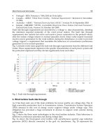
The numerical simulation results presented in Fig 6 shows the behavior of two controller
functions; (1) A linear controller (
L
f ), and (2) A sigmoid based controller (
S
f ), defined as,
,*0.3=)( aaf
L
)(1
1
0.52=)(
aexp
af
S
Remark: Lipschitz constants of the )(
L
f is 0.3 and that of )(
S
f is 0.5 (see (Uykan and
Koivo 2004)) thus the above control functions satisfy the condition in (22) and hence agree
with the theoretical proof for convergence.
Fig. 6. - Numerical results showing the convergence of the controllers. Here
50=C
and
10=(0)p
RSSBasedTechnologiesinWirelessSensorNetworks 53
where
m
i
T
m
i
RPRC
ˆ
= is a constant for the time interval. Here the
i
is the random noise
in the
m
i
R
, i.e.
i
m
i
m
i
RR
=
ˆ
. Let
)(=
T
i
PCp
, then
T
i
Pp
=
. The equation (23) can then
be written in the vector form as,
)(=)(=
ppp
,
(24)
where
T
ii
Pp =][
,
ii
=][
and
nn
:
i.e.
,)]()([=)(
1
T
n
afafa
nT
n
aaa ][=
1
and 0=)(a
if 0=a , thus the equilibrium point is the desired
transmit power in (21) giving the optimal CIR in (20). Then as in (Uykan and Koivo 2004),
selecting
a
pa = and
b
pb = yields,
.|)(||)()(||
1
|||
baba
ppkpp
(25)
Since the above expression satisfies the Lipschitz conditions the system converges toward
the desired power vector. (see (Uykan and Koivo 2004) and references there)
The numerical simulation results presented in Fig 6 shows the behavior of two controller
functions; (1) A linear controller (
L
f ), and (2) A sigmoid based controller (
S
f ), defined as,
,*0.3=)( aaf
L
)(1
1
0.52=)(
aexp
af
S
Remark: Lipschitz constants of the )(
L
f is 0.3 and that of )(
S
f is 0.5 (see (Uykan and
Koivo 2004)) thus the above control functions satisfy the condition in (22) and hence agree
with the theoretical proof for convergence.
Fig. 6. - Numerical results showing the convergence of the controllers. Here
50=C
and
10=(0)p
3.4 Experimental Results
In the experimental evaluation we use two controller configurations, (i) Centralized
implementation (see Fig 7(a)) and (ii) Decentralized implementation (see Fig 7(b)). For the
centralized implementation the server node transmits the signal strength of the received
signal back to the client node, which will be used in the power control process. This uses the
controller configuration expressed in the equation (21). In the distributed implementation,
the client nodes make use of the local signal strength measurement for the power control
process. For this approach the second configuration of the power control algorithm
expressed by the equation (23) is used.
The experimental evaluation is conducted with the Micaz transceivers (Fig 8) developed by
XBow technologies (Crossbow 2007). In Micaz hardware, the transmission power is
controlled via an index (see (Chipcon 2004) on mapping of the index to dBm). The
experiments were done for two basic cases, (i) static environment where the gains of the
communication does not change significantly with in the time interval, and (ii) dynamic
environment where the server node randomly moves within it's communication range. We
use five cases for each environment to study the performance of the control algorithms. The
controller implementation in each client node is shown in the Table 2.
Fig. 7. - Controller Configurations
MobileandWirelessCommunications:Networklayerandcircuitleveldesign54
Fig. 8. - Micaz node used for the experiment
(a) Static Environment
For this experiment we choose an environment with no or limited link gain variation
(mostly due to the receiver noise). The Fig 9 shows the variation of received power
measurements and the transmission power values of the client nodes. For this experiment,
the target received power at the server node (
t
R
) is selected as
dBm70
. According to the
experiment results, the centralized controllers perform an accurate power control than the
decentralized ones. Moreover, the centralized controllers demonstrate more robustness to
measurement errors comparing with the decentralized one.
Client No. Control Algorithm/ function
1
Centralized/
L
f
2
Centralized/
S
f
3
De-centralized/
L
f
4
De-centralized/
S
f
Table 2. - Client nodes and their controllers
RSSBasedTechnologiesinWirelessSensorNetworks 55
Fig. 8. - Micaz node used for the experiment
(a) Static Environment
For this experiment we choose an environment with no or limited link gain variation
(mostly due to the receiver noise). The Fig 9 shows the variation of received power
measurements and the transmission power values of the client nodes. For this experiment,
the target received power at the server node (
t
R
) is selected as
dBm70
. According to the
experiment results, the centralized controllers perform an accurate power control than the
decentralized ones. Moreover, the centralized controllers demonstrate more robustness to
measurement errors comparing with the decentralized one.
Client No. Control Algorithm/ function
1
Centralized/
L
f
2
Centralized/
S
f
3
De-centralized/
L
f
4
De-centralized/
S
f
Table 2. - Client nodes and their controllers
Fig. 9. - Behavior of the iterative controller in a static environment
(b) Dynamic Environment
The Figure 10 shows the variation of received power measurements and the transmission
power values of the client nodes. The target received power at the server node (
t
R
) is
selected as
dBm70
. In a dynamic environment, neither the centralized controllers nor the
decentralized controllers perform well in maintaining a constant RSS at the server node.
However, the centralized and decentralized implementation of the sigmoid function based
controller performed well than the other controller configurations.
MobileandWirelessCommunications:Networklayerandcircuitleveldesign56
Fig. 10. - Implementation of the iterative controller in a dynamic environment
4. Conclusion
The first section of this chapter introduces architecture for an all-to-all ad-hoc wireless
network that satisfies the QoS requirements as well as power saving aspects. The CDMA
based communication in the proposed network enables the operation in a very narrow band
as well as maintaining a larger member base. This makes this network extremely suitable for
military, swarm robotics and sensor network applications that require larger member base
dispersed in relatively close proximity (i.e. within the single hop range of the transmitters)
and simultaneous / delay-free communication within the network. The simulation case
studies illustrate the behaviour of the controller in ideal conditions. Moreover, the
theoretical assertions of network capacity and selection of target RSS value were illustrated.
RSSBasedTechnologiesinWirelessSensorNetworks 57
Fig. 10. - Implementation of the iterative controller in a dynamic environment
4. Conclusion
The first section of this chapter introduces architecture for an all-to-all ad-hoc wireless
network that satisfies the QoS requirements as well as power saving aspects. The CDMA
based communication in the proposed network enables the operation in a very narrow band
as well as maintaining a larger member base. This makes this network extremely suitable for
military, swarm robotics and sensor network applications that require larger member base
dispersed in relatively close proximity (i.e. within the single hop range of the transmitters)
and simultaneous / delay-free communication within the network. The simulation case
studies illustrate the behaviour of the controller in ideal conditions. Moreover, the
theoretical assertions of network capacity and selection of target RSS value were illustrated.
Moreover, the controller behaviours in dynamic and real-world scenarios are tested using
computer simulations.
In the second section of the chapter we introduced a power control algorithm which uses
RSS measurements which is facilitated by most commercially available transceivers (in
comparison with the CIR measurements presented in (Foschini and Miljanic 1993; Uykan
and Koivo 2004) etc,). Since the control scheme focuses on maintaining the least power
required for the base station / mobile data collector to capture the data packet, the clients
transmit the signal in the minimum possible power which ensures the optimal CIR for every
client. This effectively enhances the battery life of the power critical client nodes while
maintaining a better quality of service. The experimental results verify the convergence of
the power control scheme in a static environment as well as the practical applicability of the
proposed controller.
5. References
Agelet, F. A., F. P. Fontan, et al. (1997). "Fast ray tracing for microcellular and indoor
environments." Magnetics, IEEE Transactions on 33(2): 1484-1487.
Akyildiz, I. F., E. Ekici, et al. (2003). "A Distributed Multicast Routing Scheme for Multi-
Layered Satellite IP Networks." Wireless Networks 9(5): 535-544.
Almeroth, K. C. (2000). "The evolution of multicast: from the MBone to interdomain
multicast to Internet2 deployment." Network, IEEE 14(1): 10-20.
Batchelor, A., W. Y. Ochieng, et al. (1996). Design features of D-GNSS reference stations.
Satellite Systems for Mobile Communications and Navigation, 1996., Fifth
International Conference on.
Cai, M., W. Wang, et al. (2004). Power control algorithm for time-varying CDMA cellular
systems. Intelligent Mechatronics and Automation, 2004. Proceedings. 2004
International Conference on.
Chan, Y. S., J. W. Modestino, et al. (2007). "An End-to-End Embedded Approach for
Multicast/Broadcast of Scalable Video over Multiuser CDMA Wireless
Networks." Multimedia, IEEE Transactions on 9(3): 655-667.
Chen, M S., J C. Chen, et al. (1996). "On general results for all-to-all broadcast." Parallel and
Distributed Systems, IEEE Transactions on 7(4): 363-370.
Chipcon (2004). "C2240 Transceiver Datasheet." Chipcon Systems.
Cooper, G. R. and R. W. Nettleton (1978). "A spread-spectrum technique for high-capacity
mobile communications." Vehicular Technology, IEEE Transactions on 27(4): 264-
275.
Crossbow (2007). "Crossbow Technologies Incorporated."
.
Degli-Esposti, V., G. Lombardi, et al. (1998). "Measurement and ray-tracing prediction of
indoor channel parameters." Electronics Letters 34(22): 2167-2168.
ElBatt, T. and A. Ephremides (2004). "Joint scheduling and power control for wireless ad hoc
networks." Wireless Communications, IEEE Transactions on 3(1): 74-85.
Ellersick, F. (1984). "A conversation with Claude Shannon." Communications Magazine,
IEEE 22(5): 123-126.
Erceg, V., L. J. Greenstein, et al. (1999). "An empirically based path loss model for wireless
channels in suburban environments." Selected Areas in Communications, IEEE
Journal on 17(7): 1205-1211.
MobileandWirelessCommunications:Networklayerandcircuitleveldesign58
Foschini, G. J. and Z. Miljanic (1993). "A simple distributed autonomous power control
algorithm and its convergence." Vehicular Technology, IEEE Transactions on 42(4):
641-646.
Gilhousen, K. S., I. M. Jacobs, et al. (1991). "On the capacity of a cellular CDMA system."
Vehicular Technology, IEEE Transactions on 40(2): 303-312.
Gomez, J. and A. T. Campbell (2007). "Variable-Range Transmission Power Control in
Wireless Ad Hoc Networks." Mobile Computing, IEEE Transactions on 6(1): 87-99.
Grandhi, S. A., R. Vijayan, et al. (1994). "Distributed power control in cellular radio systems."
Communications, IEEE Transactions on 42(234): 226-228.
Grandhi, S. A., R. Vijayan, et al. (1993). "Centralized power control in cellular radio
systems." Vehicular Technology, IEEE Transactions on 42(4): 466-468.
Grandhi, S. A., R. D. Yates, et al. (1997). "Resource allocation for cellular radio systems."
Vehicular Technology, IEEE Transactions on 46(3): 581-587.
Guo, S. and O. Yang (2006). "A Constraint Formulation for Minimum-Energy Multicast
Routing in Wireless Multihop Ad-hoc Networks." Wireless Networks 12(1): 23-32.
Hou, Y. T., Y. Shi, et al. (2006). "Maximizing the Lifetime of Wireless Sensor Networks
through Optimal Single-Session Flow Routing." Mobile Computing, IEEE
Transactions on 5(9): 1255-1266.
Klein, T. E. and H. Viswanathan (2006). "Centralized power control and routing policies for
multihop wireless networks." Information Theory, IEEE Transactions on 52(3): 849-
866.
Knisely, D. N., S. Kumar, et al. (1998). "Evolution of wireless data services: IS-95 to
cdma2000." Communications Magazine, IEEE 36(10): 140-149.
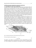
Lim, S., K. M. K. H. Leong, et al. (2005). "Adaptive power controllable retrodirective array
system for wireless sensor server applications." Microwave Theory and Techniques,
IEEE Transactions on 53(12): 3735-3743.
Lin, S., J. Zhang, et al. (2006). ATPC: adaptive transmission power control for wireless
sensor networks. Proceedings of the 4th international conference on Embedded
networked sensor systems. Boulder, Colorado, USA, ACM Press: 223-236.
Prasad, R. and T. Ojanpera (1998). A survey on CDMA: evolution towards wideband
CDMA. Spread Spectrum Techniques and Applications, 1998. Proceedings., 1998
IEEE 5th International Symposium on.
Puccinelli, D. and M. Haenggi (2006). Multipath fading in wireless sensor networks:
measurements and interpretation. Proceeding of the 2006 international conference
on Communications and mobile computing. Vancouver, British Columbia, Canada,
ACM Press: 1039-1044.
Remley, K. A., H. R. Anderson, et al. (2000). "Improving the accuracy of ray-tracing
techniques for indoor propagation modeling." Vehicular Technology, IEEE
Transactions on 49(6): 2350-2358.
Santos, R. A., O. Alvarez, et al. (2005). Experimental analysis of wireless propagation models
with mobile computing applications. Electrical and Electronics Engineering, 2005
2nd International Conference on.
Sato, R., H. Sato, et al. (2005). A SBR estimation for indoor wave propagation through
dielectric walls. Antennas and Propagation Society International Symposium, 2005
IEEE.
Schiller, J. (2003). Mobile Communications, Addison-Wesley.
RSSBasedTechnologiesinWirelessSensorNetworks 59
Foschini, G. J. and Z. Miljanic (1993). "A simple distributed autonomous power control
algorithm and its convergence." Vehicular Technology, IEEE Transactions on 42(4):
641-646.
Gilhousen, K. S., I. M. Jacobs, et al. (1991). "On the capacity of a cellular CDMA system."
Vehicular Technology, IEEE Transactions on 40(2): 303-312.
Gomez, J. and A. T. Campbell (2007). "Variable-Range Transmission Power Control in
Wireless Ad Hoc Networks." Mobile Computing, IEEE Transactions on 6(1): 87-99.
Grandhi, S. A., R. Vijayan, et al. (1994). "Distributed power control in cellular radio systems."
Communications, IEEE Transactions on 42(234): 226-228.
Grandhi, S. A., R. Vijayan, et al. (1993). "Centralized power control in cellular radio
systems." Vehicular Technology, IEEE Transactions on 42(4): 466-468.
Grandhi, S. A., R. D. Yates, et al. (1997). "Resource allocation for cellular radio systems."
Vehicular Technology, IEEE Transactions on 46(3): 581-587.
Guo, S. and O. Yang (2006). "A Constraint Formulation for Minimum-Energy Multicast
Routing in Wireless Multihop Ad-hoc Networks." Wireless Networks 12(1): 23-32.
Hou, Y. T., Y. Shi, et al. (2006). "Maximizing the Lifetime of Wireless Sensor Networks
through Optimal Single-Session Flow Routing." Mobile Computing, IEEE
Transactions on 5(9): 1255-1266.
Klein, T. E. and H. Viswanathan (2006). "Centralized power control and routing policies for
multihop wireless networks." Information Theory, IEEE Transactions on 52(3): 849-
866.
Knisely, D. N., S. Kumar, et al. (1998). "Evolution of wireless data services: IS-95 to
cdma2000." Communications Magazine, IEEE 36(10): 140-149.
Lim, S., K. M. K. H. Leong, et al. (2005). "Adaptive power controllable retrodirective array
system for wireless sensor server applications." Microwave Theory and Techniques,
IEEE Transactions on 53(12): 3735-3743.
Lin, S., J. Zhang, et al. (2006). ATPC: adaptive transmission power control for wireless
sensor networks. Proceedings of the 4th international conference on Embedded
networked sensor systems. Boulder, Colorado, USA, ACM Press: 223-236.
Prasad, R. and T. Ojanpera (1998). A survey on CDMA: evolution towards wideband
CDMA. Spread Spectrum Techniques and Applications, 1998. Proceedings., 1998
IEEE 5th International Symposium on.
Puccinelli, D. and M. Haenggi (2006). Multipath fading in wireless sensor networks:
measurements and interpretation. Proceeding of the 2006 international conference
on Communications and mobile computing. Vancouver, British Columbia, Canada,
ACM Press: 1039-1044.
Remley, K. A., H. R. Anderson, et al. (2000). "Improving the accuracy of ray-tracing
techniques for indoor propagation modeling." Vehicular Technology, IEEE
Transactions on 49(6): 2350-2358.
Santos, R. A., O. Alvarez, et al. (2005). Experimental analysis of wireless propagation models
with mobile computing applications. Electrical and Electronics Engineering, 2005
2nd International Conference on.
Sato, R., H. Sato, et al. (2005). A SBR estimation for indoor wave propagation through
dielectric walls. Antennas and Propagation Society International Symposium, 2005
IEEE.
Schiller, J. (2003). Mobile Communications, Addison-Wesley.
Scholtz, R. A. (1994). The evolution of spread-spectrum multiple-access communications.
Spread Spectrum Techniques and Applications, 1994. IEEE ISSSTA '94., IEEE Third
International Symposium on.
Tam, W. K. and V. N. Tran (1995). "Propagation modelling for indoor wireless
communication." Electronics & Communication Engineering Journal 7(5): 221-228.
Transier, M., H. Fubler, et al. (2007). "A hierarchical approach to position-based multicast for
mobile ad-hoc networks." Wireless Networks 13(4): 447-460.
Uykan, Z. and H. N. Koivo (2004). "Sigmoid-basis nonlinear power-control algorithm for
mobile radio systems." Vehicular Technology, IEEE Transactions on 53(1): 265-270.
Uykan, Z. and H. N. Koivo (2006). "Proportional power control algorithm for time varying
link gains in cellular radio systems." Vehicular Technology, IEEE Transactions on
55(1): 341-349.
Varga, R. S. (1962). Matrix Iterative Analysis. N.J., Prentis Hall, Inc.
Yang, L L. (2006). "MIMO-assisted space-code-division multiple-access: linear detectors and
performance over multipath fading channels." Selected Areas in Communications,
IEEE Journal on 24(1): 121-131.
Yang, Y. and J. Wang (1998). "On blocking probability of multicast networks."
Communications, IEEE Transactions on 46(7): 957-968.
Yang, Y. and J. Wang (2001). "Pipelined all-to-all broadcast in all-port meshes and tori."
Transactions on Computers 50(10): 1020-1032.
Zander, J. (1992). "Performance of optimum transmitter power control in cellular radio
systems." Vehicular Technology, IEEE Transactions on 41(1): 57-62.
MobileandWirelessCommunications:Networklayerandcircuitleveldesign60
SmartwirelesscommunicationplatformIQRF 61
SmartwirelesscommunicationplatformIQRF
RadekKuchta,RadimirVrbaandVladislavSulc
X
Smart wireless communication platform IQRF
Radek Kuchta, Radimir Vrba and Vladislav Sulc
Brno University of Technology, Microrisc s. r. o.
Czech Republic
1. Introduction
Wireless communications systems are used in different areas of human activity. Wireless
communications can be distinguished between licensed and non-licensed, according to the
applied frequency band. Non-licensed bands are different in a lot of countries. In European
Union, there are 433 MHz, 868 MHz, 2.5 GHz and other bands. In the United States of
America, there are 916 MHz and others. These frequencies are very often used for
interconnection of sensors, actuators, equipments, controllers, computers, remote controllers
etc. They are used at least in two basic lines of work. The first one is for home automation
and the second one is for industrial automation. Communications standards and
communication protocols exist in both of these lines.
One such standardized protocol is, for example, Zigbee. It involves a solution based on the
IEEE 802.15.4 standard (De Nardis and Di Benedetto 2007) prepared by Zigbee Alliance
(ZigBee 2009). Among the proprietary solutions, reference can be made to the technology of
MiWi launched by Microchip Technology Inc. (Flowers and Yang 2008), based on the
aforementioned standard but simpler than Zigbee from the point of view of implementation
and not allowing direct cooperation with Zigbee devices (Huang et al. 2008; Ji et al. 2008;
Song and Yang 2008). Among the other solutions available on the market, mention would be
made, for example, of the solution promoted by Z-wave alliance.
These solutions have disadvantage in attempt on being a universal solution targeting every
kind of applications. It brings heavier protocols, more difficult and more expensive
implementations.
Implementation of solutions such as Zigbee or MiWi consists of software solution stack and
hardware solution used for communication. Software solution stack is developed by a
microcontroller manufacture for defined microcontroller or by a producer that wants to
supply his products for communication modules designed for the area of domestic
automation. The software stack is a package of program routines, functional components
and program subsystems (hereinafter Stack) permitting the basic operation of the
communication module according to the chosen solution for wireless communication. The
manufacturer of the end device uses the modules for the selected communication solution,
and then, it creates a further application extension to implement the actual application
functionality of the end device (Ferrari et al. 2007; Ghazvini et al. 2008; Chan 2008; Liang et
al. 2008).
4
MobileandWirelessCommunications:Networklayerandcircuitleveldesign62
The need for this step is obvious from the point of view of the manufacturer of the processor
products – the manufacturer wants to supply his products within the framework of the
whole communication solution, and because he has the best knowledge of his own products,
he creates the Stack referred to above, generally in much less time than each individual
manufacturer of end devices would have taken to create his own product. By creating a
Stack, he thus makes it possible to participate on communication solutions based on the
processors supplied by itself, and it offers them not just to one but to many potential
customers.
Fig. 1. The first generation of IQRF communication modules
Wireless communications platforms based on the standard communication networks, such
as Wi-Fi or Bluetooth, are available on the market place. It is possible to buy a
communication module with a simple communication interface that implements all needed
functions and protocols. It is not so difficult to implement these modules and networks to
the new devices. These solutions are useful for fast communications with greater volume of
data. These modules have usually higher energy consumption, so they are not targeting low
power applications.
29,5
14,9
Fig. 2. The second generation of IQRF communication modules
There are also available proprietary solutions like Z-wave (Z-Wave 2009), radio modems
XTR-434L (Aurel 2008), nRF24xx (Leonard 2007), RC1280HP (Vojacek 2007), etc. They
usually use master/slave communication model. Sometimes, they offer other integrated
peripherals as AD converters, LEDs, or digital inputs/outputs.
Z-wave, for example, uses a mesh network topology with no master node. Any device can
originate the message. If the preferred route is unavailable, the message originator will
attempt other routes until a path is found to the recipient node. Z-wave rating units cannot
be in sleep mode.
The chapter is focused on proprietary wireless communication platform IQRF. The platform
supports different network topologies, allows fast and easy implementation to the new
applications without deeper knowledge of the issue of wireless communications.
At the beginning of the chapter main features and hardware parameters of the IQRF
platform are described. The next section contains description of the IQRF operating system
with basic functionality description. Then IQRF gateways and available development tools
are discussed. The next section contains description of IQMESH communication protocol
used by IQRF platform. At the end of the chapter is a future work description and short
summary.
2. Wireless communication platform IQRF
The IQRF platform was designed to address smaller segments of wireless market - buildings
automation and telemetry. The platform was developed by Microrisc company (Microrisc
2009b). Main parts of the platform are covered by Czech and US patents (Sulc 2007a; b; c;
2008). These patents cover a method of creating a generic network communication platform,
special signal coding scheme, and direct peripheral addressing in wireless network.
Fig. 3. The block structure of the IQRF module (Microrisc 2008a)
The IQRF platform is based on second generation of short-range radio components
produced by RFM Company (RFM 2009). It works in non-licensed communication bands.
IQRF communication modules (Microrisc 2008b) are available for 868 MHz and 916 MHz
frequencies. Basic features of this wireless communications platform are especially very low
power consumption, network possibility, programmable RF power up to 1.3 mW, optionally
up to 10 mW, 170 m range, and 15 kb/s RF bit rate, optionally 100 kb/s. The first generation
SmartwirelesscommunicationplatformIQRF 63
The need for this step is obvious from the point of view of the manufacturer of the processor
products – the manufacturer wants to supply his products within the framework of the
whole communication solution, and because he has the best knowledge of his own products,
he creates the Stack referred to above, generally in much less time than each individual
manufacturer of end devices would have taken to create his own product. By creating a
Stack, he thus makes it possible to participate on communication solutions based on the
processors supplied by itself, and it offers them not just to one but to many potential
customers.
Fig. 1. The first generation of IQRF communication modules
Wireless communications platforms based on the standard communication networks, such
as Wi-Fi or Bluetooth, are available on the market place. It is possible to buy a
communication module with a simple communication interface that implements all needed
functions and protocols. It is not so difficult to implement these modules and networks to
the new devices. These solutions are useful for fast communications with greater volume of
data. These modules have usually higher energy consumption, so they are not targeting low
power applications.
29,5
14,9
Fig. 2. The second generation of IQRF communication modules
There are also available proprietary solutions like Z-wave (Z-Wave 2009), radio modems
XTR-434L (Aurel 2008), nRF24xx (Leonard 2007), RC1280HP (Vojacek 2007), etc. They
usually use master/slave communication model. Sometimes, they offer other integrated
peripherals as AD converters, LEDs, or digital inputs/outputs.
Z-wave, for example, uses a mesh network topology with no master node. Any device can
originate the message. If the preferred route is unavailable, the message originator will
attempt other routes until a path is found to the recipient node. Z-wave rating units cannot
be in sleep mode.
The chapter is focused on proprietary wireless communication platform IQRF. The platform
supports different network topologies, allows fast and easy implementation to the new
applications without deeper knowledge of the issue of wireless communications.
At the beginning of the chapter main features and hardware parameters of the IQRF
platform are described. The next section contains description of the IQRF operating system
with basic functionality description. Then IQRF gateways and available development tools
are discussed. The next section contains description of IQMESH communication protocol
used by IQRF platform. At the end of the chapter is a future work description and short
summary.
2. Wireless communication platform IQRF
The IQRF platform was designed to address smaller segments of wireless market - buildings
automation and telemetry. The platform was developed by Microrisc company (Microrisc
2009b). Main parts of the platform are covered by Czech and US patents (Sulc 2007a; b; c;
2008). These patents cover a method of creating a generic network communication platform,
special signal coding scheme, and direct peripheral addressing in wireless network.
Fig. 3. The block structure of the IQRF module (Microrisc 2008a)
The IQRF platform is based on second generation of short-range radio components
produced by RFM Company (RFM 2009). It works in non-licensed communication bands.
IQRF communication modules (Microrisc 2008b) are available for 868 MHz and 916 MHz
frequencies. Basic features of this wireless communications platform are especially very low
power consumption, network possibility, programmable RF power up to 1.3 mW, optionally
up to 10 mW, 170 m range, and 15 kb/s RF bit rate, optionally 100 kb/s. The first generation
MobileandWirelessCommunications:Networklayerandcircuitleveldesign64
of IQRF module is in Fig. 1, the second generation is in Fig. 2. Sizes in figures are in mm. The
pictures aren’t in scale. The second generation module is the same size like SIM card and
used the same connector for interconnection with other parts of system. The block structure
of the IQRF module is shown in Fig. 3.
Basically, the IQRF communication module has three basic input/output interfaces, one
analog input, an SPI interface, and digital ports. Each module contains integrated analog
temperature sensor, LED and 3 V linear regulators, which can be used for user application.
2.1 IQRF operating system
IQRF communications modules have own operating system. SW developers don’t need to
implement any part of wireless communication protocol. They only use prepared functions
of operating system for their application. Whole system offers about 40 functions. A
function block diagram is shown in Fig. 4. The main functions of OS are:
• RF functions for transmitting, receiving, bonding and setting up,
• IIC and SPI communication functions,
• EEPROM access functions,
• three buffers for RF, COM and INFO are available,
• some other auxiliary functions for LED, OS information, delays and sleep mode
functions are available too.
Up to 32 bytes is possible to send in one packet.
Fig. 4. Basic functionality block diagram of IQRF Operating system
IQRF operating system is implemented to the program memory of the microcontroller.
Program memory is divided to two main parts. The first part is used by IQRF operating
system and the second is available for user’s application. When user’s application needs to
call some OS function, it calls function address defined in the definition file of the selected
OS version. Programmers of the application can use whole set of the microcontroller
instruction. Some restrictions for direct program memory access are applied. Because direct
program memory access instructions are not allowed in the user’s code, IQRF has
implemented functions to store and read data from the on chip integrated EEPROM
memory.
IQRF is wireless communication platform, so IQRF OS support functions to create network,
with different topology. When IQRF networking functionality is used, it network exist
coordinator and unit. They have very similar OS, differences are in the function to control
network that are implemented only in the coordinators modules.
To support wireless and network functionality tree data buffers are available. The OS also
offers functions to copy data between buffers. Buffer called RF contains wirelessly received
data or data to be transmitted. COM buffer is used to send and receive data via SPI, IIC and
UART interface. INFO buffer is used by system for block operations.
OS also offers functions for timing, power control, reset and integrated LED control.
Detailed description of all IQRF OS function is in (Microrisc 2008b).
2.2 IQRF gateways and development tools
Various gateways to common standards, such as Bluetooth, ZigBee and GSM are available.
Simple applications can use RS-232 gateway or more useful USB gateway. These simple
gateways were developed to allow connection between IQRF and other proprietary
solutions. They also allow connecting IQRF and standard PC with user’s application.
For more sophisticated applications, GSM or Ethernet gateways are available. To allow
interconnection between IQRF and standard wireless solution a Bluetooth and ZigBee
gateways are available.
Development tools allow debugging and testing of user applications using supporting
software. To provide comfortable environment for a transceiver development kits typically
contain interface connectors, battery, interface to user pins and so on.
3. IQMESH
IQMESH (Intelligent Mesh) protocol was defined in 2005 as a basic communication protocol
for IQRF device with target to address mainly low power, low data rate, small wireless
applications, like a home automation, office automation and telemetry (Microrisc 2008b).
IQRF utilize several unique and patented features, IQMESH protocol was defined to
support them.
For instance, the patented method of creating a generic network communication platform
with transceivers defines the simultaneous work of devices in two or more wireless
networks allowing network chaining (Sulc 2007b). Example of IQMESH network chaining is
shown in Fig. 5.
Two networks in Fig. 5, Network 1 and Network 2, are independent IQRF wireless
networks. Every such network has one Coordinator (C) and one or more slave Nodes paired
to the Coordinator. Both Coordinator and slave Nodes would be configured also as a
gateway (GW) providing connectivity to other standards. Multi-bonding mechanism
enables in this case the blue node N4 to work as a slave Node in the Network 1 and
simultaneously create own Network 2 as its Coordinator. Listening communication in both
networks, some packets received in the Network 1 would be forwarded to the Network 2
and vice verse. Specific behavior would be defined by application layer. This mechanism
would be used for bridging networks by just few instructions of application code (Microrisc
2008b), would be used in telemetry in power sensitive applications to reduce number of
SmartwirelesscommunicationplatformIQRF 65
of IQRF module is in Fig. 1, the second generation is in Fig. 2. Sizes in figures are in mm. The
pictures aren’t in scale. The second generation module is the same size like SIM card and
used the same connector for interconnection with other parts of system. The block structure
of the IQRF module is shown in Fig. 3.
Basically, the IQRF communication module has three basic input/output interfaces, one
analog input, an SPI interface, and digital ports. Each module contains integrated analog
temperature sensor, LED and 3 V linear regulators, which can be used for user application.
2.1 IQRF operating system
IQRF communications modules have own operating system. SW developers don’t need to
implement any part of wireless communication protocol. They only use prepared functions
of operating system for their application. Whole system offers about 40 functions. A
function block diagram is shown in Fig. 4. The main functions of OS are:
• RF functions for transmitting, receiving, bonding and setting up,
• IIC and SPI communication functions,
• EEPROM access functions,
• three buffers for RF, COM and INFO are available,
• some other auxiliary functions for LED, OS information, delays and sleep mode
functions are available too.
Up to 32 bytes is possible to send in one packet.
Fig. 4. Basic functionality block diagram of IQRF Operating system
IQRF operating system is implemented to the program memory of the microcontroller.
Program memory is divided to two main parts. The first part is used by IQRF operating
system and the second is available for user’s application. When user’s application needs to
call some OS function, it calls function address defined in the definition file of the selected
OS version. Programmers of the application can use whole set of the microcontroller
instruction. Some restrictions for direct program memory access are applied. Because direct
program memory access instructions are not allowed in the user’s code, IQRF has
implemented functions to store and read data from the on chip integrated EEPROM
memory.
IQRF is wireless communication platform, so IQRF OS support functions to create network,
with different topology. When IQRF networking functionality is used, it network exist
coordinator and unit. They have very similar OS, differences are in the function to control
network that are implemented only in the coordinators modules.
To support wireless and network functionality tree data buffers are available. The OS also
offers functions to copy data between buffers. Buffer called RF contains wirelessly received
data or data to be transmitted. COM buffer is used to send and receive data via SPI, IIC and
UART interface. INFO buffer is used by system for block operations.
OS also offers functions for timing, power control, reset and integrated LED control.
Detailed description of all IQRF OS function is in (Microrisc 2008b).
2.2 IQRF gateways and development tools
Various gateways to common standards, such as Bluetooth, ZigBee and GSM are available.
Simple applications can use RS-232 gateway or more useful USB gateway. These simple
gateways were developed to allow connection between IQRF and other proprietary
solutions. They also allow connecting IQRF and standard PC with user’s application.
For more sophisticated applications, GSM or Ethernet gateways are available. To allow
interconnection between IQRF and standard wireless solution a Bluetooth and ZigBee
gateways are available.
Development tools allow debugging and testing of user applications using supporting
software. To provide comfortable environment for a transceiver development kits typically
contain interface connectors, battery, interface to user pins and so on.
3. IQMESH
IQMESH (Intelligent Mesh) protocol was defined in 2005 as a basic communication protocol
for IQRF device with target to address mainly low power, low data rate, small wireless
applications, like a home automation, office automation and telemetry (Microrisc 2008b).
IQRF utilize several unique and patented features, IQMESH protocol was defined to
support them.
For instance, the patented method of creating a generic network communication platform
with transceivers defines the simultaneous work of devices in two or more wireless
networks allowing network chaining (Sulc 2007b). Example of IQMESH network chaining is
shown in Fig. 5.
Two networks in Fig. 5, Network 1 and Network 2, are independent IQRF wireless
networks. Every such network has one Coordinator (C) and one or more slave Nodes paired
to the Coordinator. Both Coordinator and slave Nodes would be configured also as a
gateway (GW) providing connectivity to other standards. Multi-bonding mechanism
enables in this case the blue node N4 to work as a slave Node in the Network 1 and
simultaneously create own Network 2 as its Coordinator. Listening communication in both
networks, some packets received in the Network 1 would be forwarded to the Network 2
and vice verse. Specific behavior would be defined by application layer. This mechanism
would be used for bridging networks by just few instructions of application code (Microrisc
2008b), would be used in telemetry in power sensitive applications to reduce number of
MobileandWirelessCommunications:Networklayerandcircuitleveldesign66
hops by collecting data from one networks and sending them together. It would used also as
a arbitrage mechanism to avoid interfering of two or more networks: One Coordinator
would coordinate Coordinators of the other networks, e.g., dedicate time slots to them. It is
useful especially in one channel environment, e.g., wireless systems based on ASK
(Amplitude Shift Keying) modulation.
Fig. 5. IQMESH network chaining
Patented transceiver architecture having two layers (basic routines and application layer)
provides an easy way to reduce development costs when creating connectivity applications.
Transceiver modules already include protocol support in the Basic layer (would be referred
also as a Operating System, Basic Routines, Protocol Layer, etc.), while the behavior of the
device would be customized by Application layer utilizing routines from the Basic layer. In
opposite to Solution stack, there is no need to compile protocol related routines, just
application, consequently, it saves time of application development.
A special signal coding scheme brings higher data throughput due to real time data
compression and also higher reliability and noise immunity due to perfect DC balance of the
coded signal (Sulc 2007c).
Patented direct peripheral addressing in wireless networks provides an easy way to make
open communication platforms utilizing built-in IQMESH features (Sulc 2008).
3.1 IQMESH basic
IQMESH uses mesh network topology supporting up to 240 devices: one Coordinator (C)
mastering the network and up to 239 slave Nodes (N). It brings efficient addressing scheme
using just one byte both for addressing of device and groups. Each Node provides
background routing service for network packets or can be configured as a dedicated router
(RT). Both Coordinator and Node can be setup as a Gateway (GW), specialized device
bridging IQMESH network and other standards.
IQMESH protocol supports both individual and group addressing, as well as a network
broadcasting. Besides standard features like bonding and discovery it also supports also
direct peripheral addressing.
IQMESH protocol was defined as a light and portable to the inexpensive hardware with
limited resources. Therefore, one byte internal addressing scheme was chosen, enabling to
address 240 devices and up to 15 groups.
3.2 IQMESH packets
IQMESH protocol supports a packet oriented communication scheme, both point-to-point
and more complex networking topologies (star, mesh). IQMESH protocol is flexible and
leaves possibility for future expansion. For instance, there is a byte in the NTW INFO section
of the packet defining routing algorithm. This simple mechanism allows to implement and
support more rating algorithms and/or to have them application oriented as every
application has usually very different requirements. For example, typical Smart House
application would be realized with 4-hops and there is a need for fast response, while
collecting data from power meters needs usually network supporting much more hops is
needed, latency is not a problem.
Fig. 6. IQMESH packet structure
Based on application layering, every device can accept and/or reject peer-to-peer
communication. Packets for peer - to- peer communication consists of two block - PAH
(packet header) and from DATA, while packets for networking communication consists of
three blocks - PAH (packet header), NTWINFO (networking information) and DATA. Every
block has its own consistency check mechanism to achieve high reliability even in a noisy
environment. Basic packet structure is shown at Fig. 6.
PAH (packet header), 3 bytes long block, carries basic information about a packet, such as
data length, flags if a packet is intended for peer-to-peer or networking communication,
flags indicating system communication, flags indicating routing, direct peripheral
addressing, such as encryption and acknowledgment request. NTWINFO (networking
information) block has variable length based on PAH flag definitions. This mechanism
provides an easy, reliable, while highly complex way to fit many different application needs.
For example, Star topology does not need additional routing information which is requested
in mesh networks. Setting ROUTEF = 0 will make a packet suitable for Star topology
networks, while after setting ROUTEF = 1 six bytes describing the rating algorithm will be
added to the NTWINFO.
Data load would vary between 0-255 bytes, while specific IQMESH implementations would
support only 64bytes of data. This limitation enables porting of IQMESH protocol even to
the smallest 8b microcontrollers.
Detailed IQMESH protocol description and its specifications will be publicly open and
available in June 2009 (Microrisc 2009a).
SmartwirelesscommunicationplatformIQRF 67
hops by collecting data from one networks and sending them together. It would used also as
a arbitrage mechanism to avoid interfering of two or more networks: One Coordinator
would coordinate Coordinators of the other networks, e.g., dedicate time slots to them. It is
useful especially in one channel environment, e.g., wireless systems based on ASK
(Amplitude Shift Keying) modulation.
Fig. 5. IQMESH network chaining
Patented transceiver architecture having two layers (basic routines and application layer)
provides an easy way to reduce development costs when creating connectivity applications.
Transceiver modules already include protocol support in the Basic layer (would be referred
also as a Operating System, Basic Routines, Protocol Layer, etc.), while the behavior of the
device would be customized by Application layer utilizing routines from the Basic layer. In
opposite to Solution stack, there is no need to compile protocol related routines, just
application, consequently, it saves time of application development.
A special signal coding scheme brings higher data throughput due to real time data
compression and also higher reliability and noise immunity due to perfect DC balance of the
coded signal (Sulc 2007c).
Patented direct peripheral addressing in wireless networks provides an easy way to make
open communication platforms utilizing built-in IQMESH features (Sulc 2008).
3.1 IQMESH basic
IQMESH uses mesh network topology supporting up to 240 devices: one Coordinator (C)
mastering the network and up to 239 slave Nodes (N). It brings efficient addressing scheme
using just one byte both for addressing of device and groups. Each Node provides
background routing service for network packets or can be configured as a dedicated router
(RT). Both Coordinator and Node can be setup as a Gateway (GW), specialized device
bridging IQMESH network and other standards.
IQMESH protocol supports both individual and group addressing, as well as a network
broadcasting. Besides standard features like bonding and discovery it also supports also
direct peripheral addressing.
IQMESH protocol was defined as a light and portable to the inexpensive hardware with
limited resources. Therefore, one byte internal addressing scheme was chosen, enabling to
address 240 devices and up to 15 groups.
3.2 IQMESH packets
IQMESH protocol supports a packet oriented communication scheme, both point-to-point
and more complex networking topologies (star, mesh). IQMESH protocol is flexible and
leaves possibility for future expansion. For instance, there is a byte in the NTW INFO section
of the packet defining routing algorithm. This simple mechanism allows to implement and
support more rating algorithms and/or to have them application oriented as every
application has usually very different requirements. For example, typical Smart House
application would be realized with 4-hops and there is a need for fast response, while
collecting data from power meters needs usually network supporting much more hops is
needed, latency is not a problem.
Fig. 6. IQMESH packet structure
Based on application layering, every device can accept and/or reject peer-to-peer
communication. Packets for peer - to- peer communication consists of two block - PAH
(packet header) and from DATA, while packets for networking communication consists of
three blocks - PAH (packet header), NTWINFO (networking information) and DATA. Every
block has its own consistency check mechanism to achieve high reliability even in a noisy
environment. Basic packet structure is shown at Fig. 6.
PAH (packet header), 3 bytes long block, carries basic information about a packet, such as
data length, flags if a packet is intended for peer-to-peer or networking communication,
flags indicating system communication, flags indicating routing, direct peripheral
addressing, such as encryption and acknowledgment request. NTWINFO (networking
information) block has variable length based on PAH flag definitions. This mechanism
provides an easy, reliable, while highly complex way to fit many different application needs.
For example, Star topology does not need additional routing information which is requested
in mesh networks. Setting ROUTEF = 0 will make a packet suitable for Star topology
networks, while after setting ROUTEF = 1 six bytes describing the rating algorithm will be
added to the NTWINFO.
Data load would vary between 0-255 bytes, while specific IQMESH implementations would
support only 64bytes of data. This limitation enables porting of IQMESH protocol even to
the smallest 8b microcontrollers.
Detailed IQMESH protocol description and its specifications will be publicly open and
available in June 2009 (Microrisc 2009a).
MobileandWirelessCommunications:Networklayerandcircuitleveldesign68
4. Future work
In this chapter, only main functions of the IQRF platform are described. The basic modules
are using 8bit microcontrollers (Microchip 2005) with limited space for the end user
program. The newest modules are using 16bits microcontroller where is bigger place for
user program, for implementation of some security aspect and so on.
IQMESH protocol is scalable allowing future expansion of routing algorithms. Currently
new multi channel multihop algorithms utilizing all advantages and unique features of
IQMESH protocol are under development.
The future step to simplify application development is to standardize peripherals and
services sets (further on referred as HWP profile) provided by a specific application family.
For example, a light switch would interpret data in a packet as I/O vector enabling R/W
operation to the respective I/O pins of a transceiver module. In addition to the above I/O
function, the transceiver module would support standard services like a bonding to and
unbinding from the IQRF network. In this case, the application layer of the module will
include a program sequence, interpreting packets as commands for R/W operations
enabling access to peripherals and services of the module.
5. Conclusion
IQRF is new wireless communication platform for home/office and industrial automation. It
has its own operating system for fast and easy implementation to user application.
The platform development tool contains software and hardware resources for rapid
application development and prototyping.
IQRF platform implements IQMESH protocol. The protocol was defined as a light and
portable to the inexpensive hardware with limited resources. Therefore one byte internal
addressing scheme was chosen, enabling to address 240 devices and up to 15 groups.
IQMESH protocol supports networks with up to 240 devices, one Coordinator and up to 239
slave Nodes. Each Node provides background routing service for network packets. Both
Coordinator and Node can be setup as a Gateway (GW), specialized device bridging
IQMESH network and other standards. IQMESH protocol can be fully or partially ported to
the smallest 8 bit microcontrollers.
IQMESH implements several unique and patented features - a special signal coding scheme
brings higher data throughput, higher reliability and noise immunity, two layer transceiver
architecture reduces development costs, simultaneous functioning of devices in two or more
wireless networks allows network chaining and finally, the mechanism of direct peripherals
addressing in wireless networks directly supported by IQMESH protocol provils an efficient
tool to build up open platform for wireless communication.
IQMESH protocol is scalable and ready to support new routing algorithms. All currently
supported routing schemes are ported to the smallest 8b microcontrollers. IQMESH protocol
definition will be opened, as well as public release of the definition, in June 2009.
(Microrisc
2009a)
6. Acknowledgement
The research has been supported by the Czech Ministry of Education in the frame of MSM
0021630503 MIKROSYN New Trends in Microelectronic Systems and Nanotechnologies
Research Project, partly supported by the Ministry of Industry and Trade of the Czech
Republic in a FI-IM4/034 Project Smart platform for wireless communication and partly in
2C08002 Project - KAAPS Research of Universal and Complex Autentification and
Authorization for Permanent and Mobile Computer Networks, under the National Program
of Research II.
7. References
Aurel. (2008). "Radiomodem & Data transceivers." < />wireless-modules/data-transceivers.asp> (May 8, 2009.
De Nardis, L., and Di Benedetto, M. G. (2007). "Overview of the IEEE 802.15.4/4a standards
for low data rate wireless personal data networks." In: 4th Workshop on
Positioning, Navigation and Communication 2007 (WPNC 07), T. Kaiser, K.
Jobmann, and K. Kyamakya, eds., Hannover, GERMANY, 285-289.
Ferrari, G., Medagliani, P., Di Piazza, S., and Martalo, M. (2007). "Wireless sensor networks:
Performance analysis in indoor scenarios." Eurasip Journal on Wireless
Communications and Networking.
Flowers, D., and Yang, Y. (2008). "MiWi Wireless Networking Protocol Stack."
Ghazvini, M. H. F., Vahabi, M., Rasid, M. F. A., and Abdullah, R. (2008). "Improvement of
MAC Performance for Wireless Sensor Networks." In: 13th International-
Computer-Society-of-Iran-Computer Conference, H. Sarbazi-Azad, B. Parhami, S.
G. Miremadi, and S. Hessabi, eds., Kish Isl, IRAN, 147-152.
Huang, Y. K., Hsiu, P. C., Chu, W. N., Hung, K. C., Pang, A. C., Kuo, T. W., Di, M., and
Fang, H. W. (2008). "An Integrated Deployment Tool for ZigBee-based Wireless
Sensor Networks." In: 5th International Conference on Embedded and Ubiquitous
Computing, C. Z. Xu and M. Guo, eds., Shanghai, PEOPLES R CHINA, 309-315.
Chan, H. K. (2008). "Wireless Industrial Tracking System for Factory Automation." In: 2nd
International Symposium on Intelligent Information Technology Application, Q.
Zhou and J. Luo, eds., Shanghai, PEOPLES R CHINA, 862-866.
Ji, Z. Z., Li, Y., Lu, H., and Ieee. (2008). "The Implementation of Wireless Sensor Network
node Based on ZigBee." In: 4th International Conference on Wireless
Communications, Networking and Mobile Computing, Dalian, PEOPLES R
CHINA, 3654-3657.
Leonard, J. (2007). "Non-Standard Solutions as Alternatives for Low-Cost Wireless
Communications." In: Nikkei Electronics Asia.
Liang, L. L., Huang, L. F., Jiang, X. Y., Yao, Y., and Ieee. (2008). "Design and Implementation
of Wireless Smart-home Sensor Network Based on ZigBee Protocol." In:
International Conference on communications, Circuits and Systems, Xiamen City,
PEOPLES R CHINA, 487-491.
Microchip. (2005). "PIC16F87/88 Datasheet." <> (25.4.2009,
2009).
SmartwirelesscommunicationplatformIQRF 69
4. Future work
In this chapter, only main functions of the IQRF platform are described. The basic modules
are using 8bit microcontrollers (Microchip 2005) with limited space for the end user
program. The newest modules are using 16bits microcontroller where is bigger place for
user program, for implementation of some security aspect and so on.
IQMESH protocol is scalable allowing future expansion of routing algorithms. Currently
new multi channel multihop algorithms utilizing all advantages and unique features of
IQMESH protocol are under development.
The future step to simplify application development is to standardize peripherals and
services sets (further on referred as HWP profile) provided by a specific application family.
For example, a light switch would interpret data in a packet as I/O vector enabling R/W
operation to the respective I/O pins of a transceiver module. In addition to the above I/O
function, the transceiver module would support standard services like a bonding to and
unbinding from the IQRF network. In this case, the application layer of the module will
include a program sequence, interpreting packets as commands for R/W operations
enabling access to peripherals and services of the module.
5. Conclusion
IQRF is new wireless communication platform for home/office and industrial automation. It
has its own operating system for fast and easy implementation to user application.
The platform development tool contains software and hardware resources for rapid
application development and prototyping.
IQRF platform implements IQMESH protocol. The protocol was defined as a light and
portable to the inexpensive hardware with limited resources. Therefore one byte internal
addressing scheme was chosen, enabling to address 240 devices and up to 15 groups.
IQMESH protocol supports networks with up to 240 devices, one Coordinator and up to 239
slave Nodes. Each Node provides background routing service for network packets. Both
Coordinator and Node can be setup as a Gateway (GW), specialized device bridging
IQMESH network and other standards. IQMESH protocol can be fully or partially ported to
the smallest 8 bit microcontrollers.
IQMESH implements several unique and patented features - a special signal coding scheme
brings higher data throughput, higher reliability and noise immunity, two layer transceiver
architecture reduces development costs, simultaneous functioning of devices in two or more
wireless networks allows network chaining and finally, the mechanism of direct peripherals
addressing in wireless networks directly supported by IQMESH protocol provils an efficient
tool to build up open platform for wireless communication.
IQMESH protocol is scalable and ready to support new routing algorithms. All currently
supported routing schemes are ported to the smallest 8b microcontrollers. IQMESH protocol
definition will be opened, as well as public release of the definition, in June 2009.
(Microrisc
2009a)
6. Acknowledgement
The research has been supported by the Czech Ministry of Education in the frame of MSM
0021630503 MIKROSYN New Trends in Microelectronic Systems and Nanotechnologies
Research Project, partly supported by the Ministry of Industry and Trade of the Czech
Republic in a FI-IM4/034 Project Smart platform for wireless communication and partly in
2C08002 Project - KAAPS Research of Universal and Complex Autentification and
Authorization for Permanent and Mobile Computer Networks, under the National Program
of Research II.
7. References
Aurel. (2008). "Radiomodem & Data transceivers." < />wireless-modules/data-transceivers.asp> (May 8, 2009.
De Nardis, L., and Di Benedetto, M. G. (2007). "Overview of the IEEE 802.15.4/4a standards
for low data rate wireless personal data networks." In: 4th Workshop on
Positioning, Navigation and Communication 2007 (WPNC 07), T. Kaiser, K.
Jobmann, and K. Kyamakya, eds., Hannover, GERMANY, 285-289.
Ferrari, G., Medagliani, P., Di Piazza, S., and Martalo, M. (2007). "Wireless sensor networks:
Performance analysis in indoor scenarios." Eurasip Journal on Wireless
Communications and Networking.
Flowers, D., and Yang, Y. (2008). "MiWi Wireless Networking Protocol Stack."
Ghazvini, M. H. F., Vahabi, M., Rasid, M. F. A., and Abdullah, R. (2008). "Improvement of
MAC Performance for Wireless Sensor Networks." In: 13th International-
Computer-Society-of-Iran-Computer Conference, H. Sarbazi-Azad, B. Parhami, S.
G. Miremadi, and S. Hessabi, eds., Kish Isl, IRAN, 147-152.
Huang, Y. K., Hsiu, P. C., Chu, W. N., Hung, K. C., Pang, A. C., Kuo, T. W., Di, M., and
Fang, H. W. (2008). "An Integrated Deployment Tool for ZigBee-based Wireless
Sensor Networks." In: 5th International Conference on Embedded and Ubiquitous
Computing, C. Z. Xu and M. Guo, eds., Shanghai, PEOPLES R CHINA, 309-315.
Chan, H. K. (2008). "Wireless Industrial Tracking System for Factory Automation." In: 2nd
International Symposium on Intelligent Information Technology Application, Q.
Zhou and J. Luo, eds., Shanghai, PEOPLES R CHINA, 862-866.
Ji, Z. Z., Li, Y., Lu, H., and Ieee. (2008). "The Implementation of Wireless Sensor Network
node Based on ZigBee." In: 4th International Conference on Wireless
Communications, Networking and Mobile Computing, Dalian, PEOPLES R
CHINA, 3654-3657.
Leonard, J. (2007). "Non-Standard Solutions as Alternatives for Low-Cost Wireless
Communications." In: Nikkei Electronics Asia.
Liang, L. L., Huang, L. F., Jiang, X. Y., Yao, Y., and Ieee. (2008). "Design and Implementation
of Wireless Smart-home Sensor Network Based on ZigBee Protocol." In:
International Conference on communications, Circuits and Systems, Xiamen City,
PEOPLES R CHINA, 487-491.
Microchip. (2005). "PIC16F87/88 Datasheet." <> (25.4.2009,
2009).
MobileandWirelessCommunications:Networklayerandcircuitleveldesign70
Microrisc. (2008a). "IQRF Transceiver Module Simple Block Diagram." b. p. tr 21a scheme,
ed., Microrisc s. r. o.
Microrisc. (2008b). "TR-xxx-21A Transceiver Module Data Sheet." 6.
Microrisc. (2009a). "Detailed IQMESH protocol description and its specifications will be
publicly open and available in June 2009." <> (May 10,
2009.
Microrisc. (2009b). "Microrisc Web Page." <
index.php> (May 19, 2009.
RFM. (2009). "TRC101 300-1000 MHz Transceiver." <
trc101.pdf> (May 19, 2009.
Song, T. W., and Yang, C. S. (Year). "A Connectivity Improving Mechanism for ZigBee
Wireless Sensor Networks." 5th International Conference on Embedded and
Ubiquitous Computing, Shanghai, PEOPLES R CHINA, 495-500.
Sulc, V. (2007a). "Czech Republic Patent PUV 16181 - Electronic transceiver module for
network wireless communication in electric or electronic devices or systems."
Microrisc s.r.o.
Sulc, V. (2007b). "Czech Republic Patent PUV 18340 - Module for wireless communication
between electric or electronic equipment or systems, method for its control and
method for creating generic platforms for user applications in area of wireless
communications with those modules." Microrisc s.r.o.
Sulc, V. (2007c). "US Patent 7167111 - Method of coding and/or decoding binary data for
wireless transmission, particularly for radio transmitted data, and equipment for
implementing this method."
Sulc, V. (2008). "Czech Republic Patent PUV 18679 - A method of accessing the peripherals
of a communication device in a wireless network of those communication devices,
a communication device to implement that method and a method of creating
generic network communication platforms with communication devices."
MICRORISC s. r. o., Czech Republic.
Vojacek, A. (2007). "Bezdrátová komunikace z RS-232/485 - modul RC1280HP."
Z-Wave. (2009). "Z-Wave Technology Documentation." <
modules/Zensys/> (May 3, 2009.
ZigBee. (2009). "ZigBee Aliance Web Page." < (May 5, 2009.
WirelessinFutureAutomotiveApplications 71
WirelessinFutureAutomotiveApplications
VolkerSchuermann,AurelBuda,StefanJonker,NormanPalmhofandJoergF.Wollert
X
Wireless in Future Automotive Applications
Volker Schuermann, Aurel Buda, Stefan Jonker,
Norman Palmhof and Joerg F. Wollert
Bochum University of Applied Sciences
Germany
1. Introduction
Wireless technology became a part of the everyday life of many humans. Practically
everyone possesses a mobile phone and is mobile attainable over it. Mobile phones became
our daily way companions. Thus, and with the in the meantime clearly increased efficiency
of these devices a number of new application scenarios are possible. Thereby can be fallen
back on the experiences from other areas of application, for example from the mobile phone
game market, which brought a quantity of interesting concepts out. Mobile phones
increased not only their performance; they also bring along clearly a number of efficient
communication interfaces, everything in front Bluetooth.
Also for the automobile industry the integration of mobile devices into vehicles is in the
future an interesting market, since here completely new business models can be
implemented. The chapter presents the boundary conditions for this. In addition also a
concept for the integration of mobile devices in the vehicle belongs to it. Apart from pure
aspects of communication, also the development and distribution of mobile applications are
more near regarded.
First this chapter gives an overview of in the automotive environment spread
communication technologies and their areas of application, the margin is here from short
range technologies with ranges from few meters to long range communication over several
kilometers away. Whereupon an overview of the key technology Bluetooth follows,
whereby the emphasis honor on the application-oriented parts of the specification and the
Bluetooth profiles is. Afterwards the Java Micro Edition, for the development of mobile
applications, is in the focus of the chapter; here is a special attention, on the communication
APIs and security. To the conclusion of the chapter then possibilities of the vehicle
integration are described in detail on the basis of an example.
5
MobileandWirelessCommunications:Networklayerandcircuitleveldesign72
2. Wireless technologies and their areas of application
Wireless communication already belongs to the state of the art in many areas of the
automotive environment today. Much works thereby covered off and is not noticed by the
user of the end product. First of all a general overview of the assigned wireless technologies
and their areas of application is to be given. See also for this Fig. 1.
Fig. 1. Wireless Use Cases
IEEE 802.15.4:
IEEE 802.15.4 is a short range radio technology for wireless sensor networks. It forms the
lower two protocol layers of a number of, in the automatic control engineering well-known,
communication standards for example ZigBee or WirelessHART. The focus lies in the
reliable transmission of small data sets if necessary over several hops away. In the
automotive environment IEEE 802.15.4 is to be mainly found in production plants.
WLAN:
Main field of application of WLAN is the wireless integration of notebooks into local area
networks. It looks similar also within the automobile area. Many of the diagnose tools
necessary for modern vehicles, are today PC-based, which means a simple integration of
WLAN, since both hardware and protocol stacks are present in large multiplicity at the
market. So far these tools are usually connected over cables with the vehicle, whereby the
diagnose unit must be in direct proximity to the vehicle. One is at present endeavored to
replace these in many cases unpractical cable connections e.g. if the vehicle is on a lifting
platform is, by wireless communication. First developments aim at the use of adapters,
which are attached to the ODB2 (on board diagnosis) interface. A complete integration of
WLAN in the vehicle is not impossible in the future. Further a set of comfort functions can
be realized so, for example the transmission of vcard files from the email program of the PC
to the navigation system. In addition there are ambitions to use WLAN for Ad-hoc
communication of vehicles among themselves and/or for communication of vehicles with
their environment. One speaks in this connection of Car to Car and Car to Roadside
communication.
Bluetooth:
Bluetooth is used in vehicles nowadays mainly for the free speech mechanism and the
integration of headsets. In addition especially from the comfort and multimedia area a
number of further meaningful applications can be realized, for example the playback of, on
the mobile phone stored music files on the cars audio system. More to the application
possibilities of Bluetooth follows in the further process of the chapter.
GPS, Galileo:
In the today's time almost nobody drives an unknown distance without navigation system.
But not only for the comfort of the drivers is the knowledge of an exact position of
importance. In logistic processes for example it is important to know, where certain goods
or vehicles are at the moment. In times of just in time production a special meaning comes to
that. The management of large fleets would not be possible without actual and exact
position information. The American GPS represents the state of the art here at present. The
European Galileo system up-to-date still is in the planning phase.
WIMAX, MBWA:
WIMAX (Worldwide Interoperability for Microwave Access) and MBWA (Mobile
Broadband Wireless Access) are called colloquially frequently also „wireless DSL “.With
them „the last mile" to customers is to be bridged to provide them with a DSL equivalent
access to the Internet. Operational areas are in special infrastructure-weak regions. Both
standards possess besides a mobile component, it permits the transfer of larger data sets
over a distance of some kilometers to a moving vehicle.
GSM, GPRS, UMTS:
Beside pure telephony also data communication continues to move into the foreground with
these technologies. A similar goal pursued as with WIMAX and MBWA, although with
usually smaller data rates. However these technologies in many countries offer a surface
covering net cover. In the remaining regions the net still is in the development.
RFID:
Especially in the luxury segment keyless entry and keyless go systems are a firm component
of cars. The transponders necessary for it are frequently RFID chips characterized by a very
small energy consumption which frequently get along even without battery, since they get
the energy from the surrounding electrical field.
3. Bluetooth
The intention behind the development of Bluetooth (Bluetooth SIG, 2009) (IEEE, 2002) was
replacing cables between individual devices such as mobile phones, PDA's, PC's, cordless
mice, headsets etc. Important aspects thereby were on the one hand the costs of the
WirelessinFutureAutomotiveApplications 73
2. Wireless technologies and their areas of application
Wireless communication already belongs to the state of the art in many areas of the
automotive environment today. Much works thereby covered off and is not noticed by the
user of the end product. First of all a general overview of the assigned wireless technologies
and their areas of application is to be given. See also for this Fig. 1.
Fig. 1. Wireless Use Cases
IEEE 802.15.4:
IEEE 802.15.4 is a short range radio technology for wireless sensor networks. It forms the
lower two protocol layers of a number of, in the automatic control engineering well-known,
communication standards for example ZigBee or WirelessHART. The focus lies in the
reliable transmission of small data sets if necessary over several hops away. In the
automotive environment IEEE 802.15.4 is to be mainly found in production plants.
WLAN:
Main field of application of WLAN is the wireless integration of notebooks into local area
networks. It looks similar also within the automobile area. Many of the diagnose tools
necessary for modern vehicles, are today PC-based, which means a simple integration of
WLAN, since both hardware and protocol stacks are present in large multiplicity at the
market. So far these tools are usually connected over cables with the vehicle, whereby the
diagnose unit must be in direct proximity to the vehicle. One is at present endeavored to
replace these in many cases unpractical cable connections e.g. if the vehicle is on a lifting
platform is, by wireless communication. First developments aim at the use of adapters,
which are attached to the ODB2 (on board diagnosis) interface. A complete integration of
WLAN in the vehicle is not impossible in the future. Further a set of comfort functions can
be realized so, for example the transmission of vcard files from the email program of the PC
to the navigation system. In addition there are ambitions to use WLAN for Ad-hoc
communication of vehicles among themselves and/or for communication of vehicles with
their environment. One speaks in this connection of Car to Car and Car to Roadside
communication.
Bluetooth:
Bluetooth is used in vehicles nowadays mainly for the free speech mechanism and the
integration of headsets. In addition especially from the comfort and multimedia area a
number of further meaningful applications can be realized, for example the playback of, on
the mobile phone stored music files on the cars audio system. More to the application
possibilities of Bluetooth follows in the further process of the chapter.
GPS, Galileo:
In the today's time almost nobody drives an unknown distance without navigation system.
But not only for the comfort of the drivers is the knowledge of an exact position of
importance. In logistic processes for example it is important to know, where certain goods
or vehicles are at the moment. In times of just in time production a special meaning comes to
that. The management of large fleets would not be possible without actual and exact
position information. The American GPS represents the state of the art here at present. The
European Galileo system up-to-date still is in the planning phase.
WIMAX, MBWA:
WIMAX (Worldwide Interoperability for Microwave Access) and MBWA (Mobile
Broadband Wireless Access) are called colloquially frequently also „wireless DSL “.With
them „the last mile" to customers is to be bridged to provide them with a DSL equivalent
access to the Internet. Operational areas are in special infrastructure-weak regions. Both
standards possess besides a mobile component, it permits the transfer of larger data sets
over a distance of some kilometers to a moving vehicle.
GSM, GPRS, UMTS:
Beside pure telephony also data communication continues to move into the foreground with
these technologies. A similar goal pursued as with WIMAX and MBWA, although with
usually smaller data rates. However these technologies in many countries offer a surface
covering net cover. In the remaining regions the net still is in the development.
RFID:
Especially in the luxury segment keyless entry and keyless go systems are a firm component
of cars. The transponders necessary for it are frequently RFID chips characterized by a very
small energy consumption which frequently get along even without battery, since they get
the energy from the surrounding electrical field.
3. Bluetooth
The intention behind the development of Bluetooth (Bluetooth SIG, 2009) (IEEE, 2002) was
replacing cables between individual devices such as mobile phones, PDA's, PC's, cordless
mice, headsets etc. Important aspects thereby were on the one hand the costs of the
MobileandWirelessCommunications:Networklayerandcircuitleveldesign74
individual radio modules as well as the energy efficiency of the devices working usually on
battery basis. Further it was enormously important to develop robust radio modules which
are not damaged in case of transport of the mobile devices. The connection should remain
unimpaired of other radio transmitters and be Ad-hoc, thus spontaneously to be developed.
All these aspects considered until today with the advancement of the Bluetooth standard,
additionally are the requirements to the transmission rate of such radio communications
ever more largely. Bluetooth is in the meanwhile a world-wide accepted standard, which is
very popular to due to its versatility and fail-safe characteristic also in the industrial area.
The Bluetooth architecture is essentially divided into three parts: the Bluetooth core, a
protocol layer and an application profile layer. The Bluetooth core forms the IEEE 802.15.1
standard; it consists of the lower layers, which are necessary for communication. Fig. 2
shows the principle structure of the Bluetooth protocol stack. The subchapter begins with
the Bluetooth core and its components, followed by some fundamental protocols, the
different application profiles of Bluetooth are more near explained thereafter.
Fig. 2. Bluetooth Protocol Stack
3.1 Bluetooth Core
The Bluetooth core consists of several layers and forms the standard IEEE 802.15.1 in the
actual sense. It covers the lower protocol layers beside the radio hardware also for the
setting up of connections between devices. It is possible to set up piconets with up to eight
active participants; one of them is the master of the piconet. Between the devices both
confirmed and unconfirmed communication for example for audio connections, can be
established. For applications described in this chapter however the higher protocol layers
and the services touching down on them are more interesting, therefore these are described
in detail in the following.
3.2 Protocol Layer:
Above the Bluetooth core one finds a further layer, it consists of a multiplicity of different
protocols, which represent the connection between Bluetooth core and application.
SDP:
In order to ensure the Ad-Hoc-ability of Bluetooth devices, is it necessarily that the devices
between those a connection should be made, can recognize whether the other device
supports the desired service. In order to manage this, the Bluetooth standard specifies the
Service Discovery Protocol (SDP). Hereby it is possible to query the Service Record of a
device. In the Service Records all available services of a Bluetooth device are stored, with a
unique ID and service attributes. The inquiry of the Service Record is a Client-Server
communication. The device, which would like to establish a connection to a service, sends
an SDP Client inquiry to the SDP server of the other device, this sends in the response
information about the supported services and it can be begun to establish a connection.
RFCOMM:
One usually used Bluetooth protocol is the RFCOMM (Radio Frequency Communications) -
protocol. In principle RFCOMM is used everywhere, where a Bluetooth radio link should
replace a physical cable, e.g. for the synchronization between a PDA and a PC. The
RFCOMM protocol is able to administer up to 60 virtual serial interfaces at the same time.
Other protocols like, the particularly in the mobile phone area spread, OBEX (Object
Exchange Protocol) touches down on the RFCOMM protocol, a typical application of OBEX
is the exchange of contact information between mobile phones or mobile phone and PC.
Bluetooth replaces here with a radio link the device specific data cable. Likewise many
Bluetooth profiles use the RFCOMM protocol, in the following with these is more in greater
detail dealt.
TCS:
Telephony control Protocol specification (TCS) is the substantial protocol for the controlling
of voice connections, all Telephony functions are regulated via this protocol.
BNEP:
The BNEP (Bluetooth Network Encapsulation Protocol) made possible like the name already
says the encapsulation of different packets, which arise in a cable-bound network e.g. IP
packets. Thus a Bluetooth device which is connected with the network over a Bluetooth
Access point can exchange data and thus for example can use network printers. In order to
realize this, the network packets are packed within BNEP frames, and passed to the lower
protocol layers for transmission.
WirelessinFutureAutomotiveApplications 75
individual radio modules as well as the energy efficiency of the devices working usually on
battery basis. Further it was enormously important to develop robust radio modules which
are not damaged in case of transport of the mobile devices. The connection should remain
unimpaired of other radio transmitters and be Ad-hoc, thus spontaneously to be developed.
All these aspects considered until today with the advancement of the Bluetooth standard,
additionally are the requirements to the transmission rate of such radio communications
ever more largely. Bluetooth is in the meanwhile a world-wide accepted standard, which is
very popular to due to its versatility and fail-safe characteristic also in the industrial area.
The Bluetooth architecture is essentially divided into three parts: the Bluetooth core, a
protocol layer and an application profile layer. The Bluetooth core forms the IEEE 802.15.1
standard; it consists of the lower layers, which are necessary for communication. Fig. 2
shows the principle structure of the Bluetooth protocol stack. The subchapter begins with
the Bluetooth core and its components, followed by some fundamental protocols, the
different application profiles of Bluetooth are more near explained thereafter.
Fig. 2. Bluetooth Protocol Stack
3.1 Bluetooth Core
The Bluetooth core consists of several layers and forms the standard IEEE 802.15.1 in the
actual sense. It covers the lower protocol layers beside the radio hardware also for the
setting up of connections between devices. It is possible to set up piconets with up to eight
active participants; one of them is the master of the piconet. Between the devices both
confirmed and unconfirmed communication for example for audio connections, can be
established. For applications described in this chapter however the higher protocol layers
and the services touching down on them are more interesting, therefore these are described
in detail in the following.
3.2 Protocol Layer:
Above the Bluetooth core one finds a further layer, it consists of a multiplicity of different
protocols, which represent the connection between Bluetooth core and application.
SDP:
In order to ensure the Ad-Hoc-ability of Bluetooth devices, is it necessarily that the devices
between those a connection should be made, can recognize whether the other device
supports the desired service. In order to manage this, the Bluetooth standard specifies the
Service Discovery Protocol (SDP). Hereby it is possible to query the Service Record of a
device. In the Service Records all available services of a Bluetooth device are stored, with a
unique ID and service attributes. The inquiry of the Service Record is a Client-Server
communication. The device, which would like to establish a connection to a service, sends
an SDP Client inquiry to the SDP server of the other device, this sends in the response
information about the supported services and it can be begun to establish a connection.
RFCOMM:
One usually used Bluetooth protocol is the RFCOMM (Radio Frequency Communications) -
protocol. In principle RFCOMM is used everywhere, where a Bluetooth radio link should
replace a physical cable, e.g. for the synchronization between a PDA and a PC. The
RFCOMM protocol is able to administer up to 60 virtual serial interfaces at the same time.
Other protocols like, the particularly in the mobile phone area spread, OBEX (Object
Exchange Protocol) touches down on the RFCOMM protocol, a typical application of OBEX
is the exchange of contact information between mobile phones or mobile phone and PC.
Bluetooth replaces here with a radio link the device specific data cable. Likewise many
Bluetooth profiles use the RFCOMM protocol, in the following with these is more in greater
detail dealt.
TCS:
Telephony control Protocol specification (TCS) is the substantial protocol for the controlling
of voice connections, all Telephony functions are regulated via this protocol.
BNEP:
The BNEP (Bluetooth Network Encapsulation Protocol) made possible like the name already
says the encapsulation of different packets, which arise in a cable-bound network e.g. IP
packets. Thus a Bluetooth device which is connected with the network over a Bluetooth
Access point can exchange data and thus for example can use network printers. In order to
realize this, the network packets are packed within BNEP frames, and passed to the lower
protocol layers for transmission.