Mobile and Wireless Communications-Physical layer development and implementation 2012 Part 7 pptx
Bạn đang xem bản rút gọn của tài liệu. Xem và tải ngay bản đầy đủ của tài liệu tại đây (872.87 KB, 20 trang )
Space-TimeDiversityTechniquesforWCDMAHighAltitudePlatformSystems 111
with K = M ⋅ N as the total number of users in all cells and p
w
is the additive white
Gaussian noise (AWGN) at the receiver, γ
req
m,n
→ γ
req
i
, g
m
′
,n
′
(θ
m
′
) → g
k
(θ
m
′
), g
m,n
(θ
m
) →
g
i
(θ
m
), p
tx
m
′
,n
′
→ p
tx
k
are performed according to the index mapping rules in equation (15).
To solve for the transmitter power p
tx
k
of each of the K individual UE simultaneously,
equation (14) can be reformulated into a matrix form as
p
tx
=
(
I −A
)
−1
b, (16)
where the calculated vector p
tx
contains the necessary transmitter power level assigned to
each of the K UE to fulfil the SINR requirement and where matrix
[
A
]
K×K
and vector
[
b
]
K×1
are defined as
[a
ik
]
K×K
= γ
req
i
⋅
g
k
(θ
m
′
)
g
i
(θ
m
)
for n
′
∕= n and
[a
ik
] = 0 for n
′
= n, [b
i
]
K×1
= γ
req
i
⋅
p
w
g
i
(θ
m
)
,
m
=
{
1,2,. , M
}
, n =
{
1,2,. , N
}
, i = 1 + (n −1) + N(m −1)
m
′
=
{
1,2,. , M
}
, n
′
=
{
1,2,. , N
}
, k = 1 + (n
′
−1) + N(m
′
−1)
(17)
Using the p
rx
= g ⊙ p
tx
, where ⊙ denotes an elementwise multiplication and g is the total
channel gain vector
[
g
k
]
K×1
for all k =
{
1,2,. , K
}
users, then all elements in the vector p
rx
for
each block that contain the UE of each of the M cells are balanced. The total cell interference
can then be calculated as
I
own
m
(θ
m
) =
N
∑
n=1
p
rx
m,n
(θ
m
), m =
{
1,2,. , M
}
(18)
I
oth
m
(θ
m
) =
M
∑
m
′
=1
m
′
∕=m
N
∑
n=1
p
rx
m
′
,n
(θ
m
′
) + p
w
, m =
{
1,2,. , M
}
(19)
where p
w
is the thermal noise at the receiver, I
own
m
(θ
m
) is the interference from the UE within
the own cell m and I
oth
m
(θ
m
) is the interference from the UE in the M − 1 other cells where
M is the total number of cells. We can now calculate i
UL
(θ
m
) which defines the other to own
interference ratio for the uplink to HAP m and is given by
i
UL
(θ
m
) =
I
oth
m
(θ
m
)
I
own
m
(θ
m
)
. (20)
This is a performance measure of the simulated system capacity at a specific elevation angle
θ
m
towards the HAP (see figure 1). If i
UL
(θ
m
) is between zero and one there is possibility
to have multiple HAP base stations covering the same coverage area. The actual number of
users that can access the HAP base stations is also dependent of which data rate each user is
using for transmission.
R
d
m
q
m
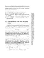
Fig. 4. A plot illustrating the change of HAP position d
m
to create different elevation angles
θ
m
.
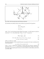
4. Simulation Results
In this simulation we assume M HAPs uniformly located along a circular boundary, with
the centre of the circular boundary acting as the pointing direction of the HAPs base station
antennas which simulate several overlapping cells, see figure 1. The beamwidth of these base
station antennas are determined by the radius of the cell coverage area (see figures 1 and 3).
These results are acquired through running Monte Carlo simulations of the multiple HAP
system. The aim of the simulation is to assess the effect of adding more HAPs on the system’s
capacity and of the impact of using space-time diversity techniques. The distance d
m
between
the cell centre and the vertical projection of the HAP on the earth’s surface is denoted as
”distance on the ground” and is varied from 0 to 70 km with a fixed cell position, as shown
in figure 4. The distance to the cell centre is also changing the elevation angle θ
m
towards the
HAP base station m as seen from the user. The cell radius has been set to 10 km and 30 km, and
the HAP altitude is 20 km. Each HAP base station serves 100 users within each corresponding
cell.
From figure 5 it is clear that with the smaller cell radius (10 km) the worst case scenario will
occur when all the HAPs are stacked on top of each other at 90 degrees elevation angle from
the cell centre (i.e., at a distance d
m
on the ground of 0 km). In the larger cell radius case
(30 km) the worst case scenario happens approximately at 30 km which is at the edge of the
cell.
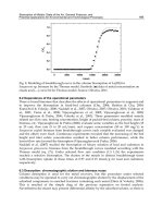
Comparing the bottom diagram in figure 5 with the two diagrams in figure 6, we can see that
if we utilize a maximum allowed other-to-own interference ratio equal to one, then as the
service data rate decreases, the number of possible HAP base stations covering the same area
can increase from 2-4 HAPs (depending on the distance d
m
between the cell centre and the
vertical projection of the HAP on the ground) for the combined service (12 kbps and 384 kbps)
to 6 HAPs with the same service (12 kbps on all HAPs).
Next, we analyze the impact of different space-time diversity techniques (SIMO and MIMO)
on the possible number of HAPs that can coexist within the same cell area and compare them
to a single-input single-output (SISO) system. From figure 7 it is obvious that using a space-
MobileandWirelessCommunications:Physicallayerdevelopmentandimplementation112
Fig. 5. The performance of the voice service (12 kbps) from one HAP in combination with
the data service (384 kbps) on the remaining HAPs for cell radius of 10 km (top) and 30 km
(bottom). The distance on the ground dm is varied from 0 to 70 km.
0 10 20 30 40 50 60 70
0.1
0.2
0.3
0.4
0.5
0.6
0.7
0.8
0.9
1
1.1
Distance on the ground [km]
Other to Own interference ratio i
ul
5 HAPs
4 HAPs
3 HAPs
2 HAPs
0 10 20 30 40 50 60 70
0
0.2
0.4
0.6
0.8
1
1.2
1.4
Distance on the ground [km]
Other to Own interference ratio i
ul
6 HAPs
5 HAPs
4 HAPs
3 HAPs
2 HAPs
7 HAPs
Fig. 6. The other to own interference ratio obtained for a 30 km cell radius for: (top) the
performance of the voice service (12 kbps) from one HAP in combination with the data service
(144 kbps) on the remaining HAPs and (bottom) the performance when we have voice services
(12 kbps) on all HAPs. The distance on the ground d
m
is varied from 0 to 70 km.
Space-TimeDiversityTechniquesforWCDMAHighAltitudePlatformSystems 113
Fig. 5. The performance of the voice service (12 kbps) from one HAP in combination with
the data service (384 kbps) on the remaining HAPs for cell radius of 10 km (top) and 30 km
(bottom). The distance on the ground dm is varied from 0 to 70 km.
0 10 20 30 40 50 60 70
0.1
0.2
0.3
0.4
0.5
0.6
0.7
0.8
0.9
1
1.1
Distance on the ground [km]
Other to Own interference ratio i
ul
5 HAPs
4 HAPs
3 HAPs
2 HAPs
0 10 20 30 40 50 60 70
0
0.2
0.4
0.6
0.8
1
1.2
1.4
Distance on the ground [km]
Other to Own interference ratio i
ul
6 HAPs
5 HAPs
4 HAPs
3 HAPs
2 HAPs
7 HAPs
Fig. 6. The other to own interference ratio obtained for a 30 km cell radius for: (top) the
performance of the voice service (12 kbps) from one HAP in combination with the data service
(144 kbps) on the remaining HAPs and (bottom) the performance when we have voice services
(12 kbps) on all HAPs. The distance on the ground d
m
is varied from 0 to 70 km.
MobileandWirelessCommunications:Physicallayerdevelopmentandimplementation114
0 10 20 30 40 50 60 70 80
0
0.1
0.2
0.3
0.4
0.5
0.6
0.7
0.8
0.9
1
Distance on the ground d
m
[km]
Other to own interference ratio i
UL
SISO
1x2 SIMO
1x4 SIMO
2x2 MIMO
2x4 MIMO
4x4 MIMO
8x8 MIMO
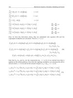
Fig. 7. The other to own interference ratio obtained for a 30 km cell radius for the performance
of the voice service (12 kbps) from one HAP in combination with the data service (384 kbps) on
the remaining two HAPs and utilizing different SISO, SIMO and MIMO space-time diversity
systems. The distance on the ground d
m
is varied from 0 to 70 km.
time diversity technique will enhance the interference mitigating capability and improve the
overall performance of the multiple HAP system. This interference mitigation technique can
also be interpreted as a capacity improvement, which is clearly seen in figure 7 for a three
HAP system and in figure 8 for a seven HAP system. In both of these figures we can observe a
decrease in the other-to-own interference ratio as we use an increasing number of antennas at
the transmitter and receiver, which in turn will allow more HAPs to provide wireless service
to more users by utilizing the remaining degrees of freedom of the system.
0 10 20 30 40 50 60 70
0
0.2
0.4
0.6
0.8
1
1.2
1.4
1.6
Distance on the ground d
m
[km]
Other to own interference ratio i
UL
SISO
1x2 SIMO
2x2 MIMO
4x4 MIMO
8x8 MIMO
Fig. 8. The other to own interference ratio obtained for a 30 km cell radius for the performance
of the voice service (12 kbps) from one HAP in combination with the data service (384 kbps) on
the remaining six HAPs and utilizing different SISO, SIMO and MIMO space-time diversity
systems. The distance on the ground d
m
is varied from 0 to 70 km.
Comparing the graphs in figure 8, we can observe that a seven HAP system using SISO would
not be possible due to the interference. However, a SIMO diversity system (utilizing two re-
ceiving antennas at the HAP base station) would make a seven HAP system possible. Adding
more antennas at the receiver and transmitter respectively will increase the number of possible
HAPs that can be used in the multiple HAP system. However, the benefit of the diversity sys-
tem will diminish even with increasing the number of antennas beyond a certain limit. From
figure 7 and figure 8 it is obvious that this limit is obtained at approximately a 4x4 MIMO sys-
tem, beyond which diversity gain is negligible as is evident from the graph of the 8x8 MIMO
system.
It is also clear from figure 6 that the worst case distance (highest interference level) is at ap-
proximately 30 km, and consequently a worst case elevation angle of 34 degrees. This maxi-
mum interference level depends on the cell radius chosen for the HAP base station as shown
in figure 9. Simulation results show that for cell radii larger than 10 km the maximum inter-
ference level will occur at the cell boundary.
5. Conclusions
In this chapter we have investigated the possibility of multiple HAP coverage of a common
cell area in WCDMA systems with and without space-time diversity techniques. Simulation
results have shown that as the service data rate decreases, the number of possible HAP base
stations that can be deployed to cover the same geographical area increases. It has further been
shown that this increment in number of HAP base stations can be enhanced to some extent by
using space-time diversity techniques. We have also shown that the worst case position of the
HAPs is in the centre of the cell if the cell radius is small (
≤ 20 km) and at the cell boundary
for large cells (
≥ 20 km). We can conclude that there is a possibility of deploying 3-5 (SISO),
or 5-8 (1x2 SIMO, 2x2 MIMO and 4x4 MIMO) HAPs covering the same cell area in response to
an increase in traffic demands, depending on the type of service used. There also appear to be
Space-TimeDiversityTechniquesforWCDMAHighAltitudePlatformSystems 115
0 10 20 30 40 50 60 70 80
0
0.1
0.2
0.3
0.4
0.5
0.6
0.7
0.8
0.9
1
Distance on the ground d
m
[km]
Other to own interference ratio i
UL
SISO
1x2 SIMO
1x4 SIMO
2x2 MIMO
2x4 MIMO
4x4 MIMO
8x8 MIMO
Fig. 7. The other to own interference ratio obtained for a 30 km cell radius for the performance
of the voice service (12 kbps) from one HAP in combination with the data service (384 kbps) on
the remaining two HAPs and utilizing different SISO, SIMO and MIMO space-time diversity
systems. The distance on the ground d
m
is varied from 0 to 70 km.
time diversity technique will enhance the interference mitigating capability and improve the
overall performance of the multiple HAP system. This interference mitigation technique can
also be interpreted as a capacity improvement, which is clearly seen in figure 7 for a three
HAP system and in figure 8 for a seven HAP system. In both of these figures we can observe a
decrease in the other-to-own interference ratio as we use an increasing number of antennas at
the transmitter and receiver, which in turn will allow more HAPs to provide wireless service
to more users by utilizing the remaining degrees of freedom of the system.
0 10 20 30 40 50 60 70
0
0.2
0.4
0.6
0.8
1
1.2
1.4
1.6
Distance on the ground d
m
[km]
Other to own interference ratio i
UL
SISO
1x2 SIMO
2x2 MIMO
4x4 MIMO
8x8 MIMO
Fig. 8. The other to own interference ratio obtained for a 30 km cell radius for the performance
of the voice service (12 kbps) from one HAP in combination with the data service (384 kbps) on
the remaining six HAPs and utilizing different SISO, SIMO and MIMO space-time diversity
systems. The distance on the ground d
m
is varied from 0 to 70 km.
Comparing the graphs in figure 8, we can observe that a seven HAP system using SISO would
not be possible due to the interference. However, a SIMO diversity system (utilizing two re-
ceiving antennas at the HAP base station) would make a seven HAP system possible. Adding
more antennas at the receiver and transmitter respectively will increase the number of possible
HAPs that can be used in the multiple HAP system. However, the benefit of the diversity sys-
tem will diminish even with increasing the number of antennas beyond a certain limit. From
figure 7 and figure 8 it is obvious that this limit is obtained at approximately a 4x4 MIMO sys-
tem, beyond which diversity gain is negligible as is evident from the graph of the 8x8 MIMO
system.
It is also clear from figure 6 that the worst case distance (highest interference level) is at ap-
proximately 30 km, and consequently a worst case elevation angle of 34 degrees. This maxi-
mum interference level depends on the cell radius chosen for the HAP base station as shown
in figure 9. Simulation results show that for cell radii larger than 10 km the maximum inter-
ference level will occur at the cell boundary.
5. Conclusions
In this chapter we have investigated the possibility of multiple HAP coverage of a common
cell area in WCDMA systems with and without space-time diversity techniques. Simulation
results have shown that as the service data rate decreases, the number of possible HAP base
stations that can be deployed to cover the same geographical area increases. It has further been
shown that this increment in number of HAP base stations can be enhanced to some extent by
using space-time diversity techniques. We have also shown that the worst case position of the
HAPs is in the centre of the cell if the cell radius is small (
≤ 20 km) and at the cell boundary
for large cells (
≥ 20 km). We can conclude that there is a possibility of deploying 3-5 (SISO),
or 5-8 (1x2 SIMO, 2x2 MIMO and 4x4 MIMO) HAPs covering the same cell area in response to
an increase in traffic demands, depending on the type of service used. There also appear to be
MobileandWirelessCommunications:Physicallayerdevelopmentandimplementation116
0 10 20 30 40 50 60 70 80
0
0.1
0.2
0.3
0.4
0.5
0.6
0.7
0.8
0.9
1
Distance on the ground [km]
Other to Own interference ratio i
ul
50 km
30 km
20 km
10 km
5 km
Fig. 9. Illustrating the effect of HAP base station cell radius on interference levels. A system
of 3 HAPs is utilized here and a voice service (12 kbps) from one HAP in combination with
the data service (384 kbps) on the other HAPs. The distance on the ground d
m
is varied from
0 to 70 km.
a limit on the number of HAPs that could be deployed using space-time diversity techniques.
Simulation results have shown that the maximum number of HAPs that could be sustained is
approximately eight when using the voice services with 4x4 MIMO on all HAPs and users.
6. References
3GPP (2005). Base station (BS) radio transmission
and reception. 3GPP TS 25.104, 2005.
Balanis, C. (1997). Antenna theory: analysis and design, Chapter 6, John Wiley, 1997.
Chen, G.; Grace, D. & Tozer, T. (2005). Performance of multiple HAPs using directive HAP and
user antennas. International Journal of Wireless Personal Communications - Special
issue on High Altitude Platforms, Vol. 32, No. 3-4, February 2005, 275 -299.
Collela, N; Martin, J. & Akyildiz, I. (2000). The HALO network. IEEE Communications
Magazine, Vol. 38, No. 6, June 2000, 142-148.
Djuknic, G.; Freidenfelds, J. & Okunev, Y. (1997). Establishing wireless communications
services via high-altitude aeronautical platforms: a concept whose time has come?.
IEEE Communications Magazine, Vol. 35, No. 9, September 1997, 128-135.
Dovis, F.; Fantini, R.; Mondin, M. & Savi, P. (2002). Small-scale fading for high-
altitude platform (HAP) propagation channels. IEEE Journal on Selected Areas in
Communications, Vol. 20, No. 3, April 2002, 641-647.
El-Jabu, B. & Steele, R. (2001). Cellular communications using aerial platforms. IEEE
Transactions on Vehicular Technology, Vol. 50, May 2001, 686-700.
Falletti, E.; Mondin, M.; Dovis, F. & Grace, D. (2003). Integration of a HAP within a terrestrial
UMTS network: interference analysis and cell dimensioning. International Journal
Wireless Personal Communications - Special Issue on Broadband Mobile Terrestrial-Satellite
Integrated Systems, Vol. 24, No. 2, February 2003, 291-325.
Falletti, E. & Sellone, F. (2005). A multi-antenna channel simulatorfor transmit and receive
smart antennas systems. IEEE Transactions on Vehicular Technology, June 2005.
Foo, Y.; Lim, W. & Tafazolli, R. (2000). Performance of high altitude platform station (HAPS)
in delivery of IMT-2000 W-CDMA. Stratospheric Platform Systems Workshop, Tokyo,
Japan, September 2000.
Grace, D; Daly, N.; Tozer, T.; Burr, A. & Pearce, D. (2001). Providing multimedia
communications from high altitude platforms, International Journal of Satellite
communications, Vol. 19, No. 6, November 2001, pp. 559-580.
Grace, D.; Spillard, C.; Thornton, J. & Tozer, T. (2002). Channel assignment strategies for a
high altitude platform spot-beam architecture. IEEE PIMRC 2002, Lisbon, Portugal,
September 2002.
Grace, D.; Mohorcic, M.; Capstick, M.; Pallavicini, B. & Fitch, M. (2005). Integrating
users into the wider broadband network via high altitude platforms. IEEE Wireless
Communications, Vol. 12, No. 5, October 2005, 98-105.
Grace, D.; Thornton, J.; Chen, G.; White, G. & Tozer, T. (2005). Improving the system capacity
of broadband services using multiple high altitude platforms, IEEE Transactions on
Wireless Communications, Vol. 4, No. 2, March 2005, 700-709.
Grace, D. & Likitthanasate, P. (2006). A business modelling approach for broadband services
from high altitude platforms. ICT’06, Madeira, Portugal, May 2006.
Goldhirsch, J. & Vogel, W. (1992). Propagation effects for land and mobile satellite systems:
overview of experimental and modelling results. NASA Ref. Publication 1274,
February 1992.
ITUa (2000). Recommendation ITU-R M.1456. Minimum Performance characteristics and
operational conditions for high altitude platform stations providing IMT-2000 in the
bands 1885-1980 MHz, 2010-2025 MHz and 2110-2170 MHz in the Regions 1 and 3
and 1885-1980 MHz and 2110-2160 MHz in Region 2. International Telecommunications
Union, 2000.
ITUb (2000). Recommendation ITU-R F.1500. Preferred characteristics of systems in the fixed
service using high-altitude platform stations operating in the Bands 47.2-47.5 GHz
and 47.9-48.2 GHz. International Telecommunications Union, 2000.
Liu, Y.; Grace, D. & Mitchell, P. (2005) Effective system spectral efficiency applied to a multiple
high altitude platform system, IEE Proceedings - Communications, Vol. 152, No. 6,
December 2005, 855-860.
Li, C. & Wang, X. (2004). Performance Comparisons of MIMO Techniques with Application
to WCDMA Systems. EURASIP Journal on Applied Signal Processing, Vol. 2004, No. 5,
2004, 49-661.
Masumura, S. & Nakagawa, M. (2002). Joint system of terrestrial and high altitude platform
stations (HAPS) cellular for W-CDMA mobile communications, IEICE Transactions on
Communications, Vol.E85-B, No. 10, October 2002, 2051-2058.
Miura, R. & Oodo, M. (2001). Wireless communications system using stratospheric platforms.
Journal of the Communication Research Laboratory, Vol. 48, No.4, 2001, 33-48.
Oodo, M.; Miura, R.; Hori, T.; Morisaki, T.; Kashiki, K. & Suzuki, M. (2002). Sharing and
compatability study between fixed service using high altitude platform stations
(HAPs) and other services in 31/28 GHz bands, Wireless Personal Communications,
Vol. 23, 2002, 3-14.
Space-TimeDiversityTechniquesforWCDMAHighAltitudePlatformSystems 117
0 10 20 30 40 50 60 70 80
0
0.1
0.2
0.3
0.4
0.5
0.6
0.7
0.8
0.9
1
Distance on the ground [km]
Other to Own interference ratio i
ul
50 km
30 km
20 km
10 km
5 km
Fig. 9. Illustrating the effect of HAP base station cell radius on interference levels. A system
of 3 HAPs is utilized here and a voice service (12 kbps) from one HAP in combination with
the data service (384 kbps) on the other HAPs. The distance on the ground d
m
is varied from
0 to 70 km.
a limit on the number of HAPs that could be deployed using space-time diversity techniques.
Simulation results have shown that the maximum number of HAPs that could be sustained is
approximately eight when using the voice services with 4x4 MIMO on all HAPs and users.
6. References
3GPP (2005). Base station (BS) radio transmission
and reception. 3GPP TS 25.104, 2005.
Balanis, C. (1997). Antenna theory: analysis and design, Chapter 6, John Wiley, 1997.
Chen, G.; Grace, D. & Tozer, T. (2005). Performance of multiple HAPs using directive HAP and
user antennas. International Journal of Wireless Personal Communications - Special
issue on High Altitude Platforms, Vol. 32, No. 3-4, February 2005, 275 -299.
Collela, N; Martin, J. & Akyildiz, I. (2000). The HALO network. IEEE Communications
Magazine, Vol. 38, No. 6, June 2000, 142-148.
Djuknic, G.; Freidenfelds, J. & Okunev, Y. (1997). Establishing wireless communications
services via high-altitude aeronautical platforms: a concept whose time has come?.
IEEE Communications Magazine, Vol. 35, No. 9, September 1997, 128-135.
Dovis, F.; Fantini, R.; Mondin, M. & Savi, P. (2002). Small-scale fading for high-
altitude platform (HAP) propagation channels. IEEE Journal on Selected Areas in
Communications, Vol. 20, No. 3, April 2002, 641-647.
El-Jabu, B. & Steele, R. (2001). Cellular communications using aerial platforms. IEEE
Transactions on Vehicular Technology, Vol. 50, May 2001, 686-700.
Falletti, E.; Mondin, M.; Dovis, F. & Grace, D. (2003). Integration of a HAP within a terrestrial
UMTS network: interference analysis and cell dimensioning. International Journal
Wireless Personal Communications - Special Issue on Broadband Mobile Terrestrial-Satellite
Integrated Systems, Vol. 24, No. 2, February 2003, 291-325.
Falletti, E. & Sellone, F. (2005). A multi-antenna channel simulatorfor transmit and receive
smart antennas systems. IEEE Transactions on Vehicular Technology, June 2005.
Foo, Y.; Lim, W. & Tafazolli, R. (2000). Performance of high altitude platform station (HAPS)
in delivery of IMT-2000 W-CDMA. Stratospheric Platform Systems Workshop, Tokyo,
Japan, September 2000.
Grace, D; Daly, N.; Tozer, T.; Burr, A. & Pearce, D. (2001). Providing multimedia
communications from high altitude platforms, International Journal of Satellite
communications, Vol. 19, No. 6, November 2001, pp. 559-580.
Grace, D.; Spillard, C.; Thornton, J. & Tozer, T. (2002). Channel assignment strategies for a
high altitude platform spot-beam architecture. IEEE PIMRC 2002, Lisbon, Portugal,
September 2002.
Grace, D.; Mohorcic, M.; Capstick, M.; Pallavicini, B. & Fitch, M. (2005). Integrating
users into the wider broadband network via high altitude platforms. IEEE Wireless
Communications, Vol. 12, No. 5, October 2005, 98-105.
Grace, D.; Thornton, J.; Chen, G.; White, G. & Tozer, T. (2005). Improving the system capacity
of broadband services using multiple high altitude platforms, IEEE Transactions on
Wireless Communications, Vol. 4, No. 2, March 2005, 700-709.
Grace, D. & Likitthanasate, P. (2006). A business modelling approach for broadband services
from high altitude platforms. ICT’06, Madeira, Portugal, May 2006.
Goldhirsch, J. & Vogel, W. (1992). Propagation effects for land and mobile satellite systems:
overview of experimental and modelling results. NASA Ref. Publication 1274,
February 1992.
ITUa (2000). Recommendation ITU-R M.1456. Minimum Performance characteristics and
operational conditions for high altitude platform stations providing IMT-2000 in the
bands 1885-1980 MHz, 2010-2025 MHz and 2110-2170 MHz in the Regions 1 and 3
and 1885-1980 MHz and 2110-2160 MHz in Region 2. International Telecommunications
Union, 2000.
ITUb (2000). Recommendation ITU-R F.1500. Preferred characteristics of systems in the fixed
service using high-altitude platform stations operating in the Bands 47.2-47.5 GHz
and 47.9-48.2 GHz. International Telecommunications Union, 2000.
Liu, Y.; Grace, D. & Mitchell, P. (2005) Effective system spectral efficiency applied to a multiple
high altitude platform system, IEE Proceedings - Communications, Vol. 152, No. 6,
December 2005, 855-860.
Li, C. & Wang, X. (2004). Performance Comparisons of MIMO Techniques with Application
to WCDMA Systems. EURASIP Journal on Applied Signal Processing, Vol. 2004, No. 5,
2004, 49-661.
Masumura, S. & Nakagawa, M. (2002). Joint system of terrestrial and high altitude platform
stations (HAPS) cellular for W-CDMA mobile communications, IEICE Transactions on
Communications, Vol.E85-B, No. 10, October 2002, 2051-2058.
Miura, R. & Oodo, M. (2001). Wireless communications system using stratospheric platforms.
Journal of the Communication Research Laboratory, Vol. 48, No.4, 2001, 33-48.
Oodo, M.; Miura, R.; Hori, T.; Morisaki, T.; Kashiki, K. & Suzuki, M. (2002). Sharing and
compatability study between fixed service using high altitude platform stations
(HAPs) and other services in 31/28 GHz bands, Wireless Personal Communications,
Vol. 23, 2002, 3-14.
MobileandWirelessCommunications:Physicallayerdevelopmentandimplementation118
Park, J.; Ku, B.; Kim, Y. & Ahn, D. (2002). Technology development for wireless
communications system using stratospheric platform in Korea. IEEE PIMRC 2002,
pp. 1577-1581, Lisbon, Portugal, Sept 2002.
Parks, M.; Butt, G.; Evans, B. & Richharia, R. (1993). Results of multiband (L, S, Ku Band)
propagation measurements and model for high elevation angle land mobile satellite
channel. Proceedings of XVII NAPEX Conference, pp. 193-202, Pasadena, California,
USA, June 1993.
Steele, R. (1992). Guest Editorial: An update on personal communications, IEEE
Communications Magazine, December 1992, 30-31.
Thornton, J.; Grace, D.; Spillard, C.; Konefal, T. & Tozer, T. (2001). Broadband Communications
from a High Altitude Platform - The European HeliNet Programme. IEE Electronics
and Communications Engineering Journal, Vol. 13, No.3, June 2001. 138-144.
Thornton, J.; Grace, D.; Capstick, M. & Tozer, T. (2003). Optimising an Array of antennas
for cellular coverage from a high altitude platform, IEEE Transactions on Wireless
communications, Vol. 2, No. 3, May 2003, 484-492.
Thornton, J. & Grace, D. (2005). Effect of lateral displacement of a high altitude platform on cel-
lular interference and handover. IEEE Transactions on Wireless Communications, Vol. 4,
No. 4, July 2005, 1483-1490.
Tozer, T. & Grace, D. (2001). High-altitude platforms for wireless communications, IEE
Electronics and Communications Engineering Journal, June 2001, Vol. 13, No. 3, 127-137.
Vazquez-Castro, M.; Belay-Zelek, D. & Curieses-Guerrero, A. (2002). Availability of systems
based on satellites with spatial diversity and HAPS, Electronics Letters, Vol. 38, No. 6,
286-287.
High-Rate,ReliableCommunicationswithHybridSpace-TimeCodes 119
High-Rate,ReliableCommunicationswithHybridSpace-TimeCodes
JoaquínCortezandMiguelBazdresch
X
High-Rate, Reliable Communications with
Hybrid Space-Time Codes
Joaquín Cortez
1
and Miguel Bazdresch
2
1
Instituto Tecnológico de Sonora
2
Instituto Tecnológico de Estudios Superiores de Occidente
México
1. Introduction
Current wireless services and applications, such as third-generation (3G) cellular systems
and Wi-Fi networks, offer capabilities far beyond what was previously available. With data
rates on the order of 100kbit/s for mobile cellular users and up to 54Mbit/s on fixed
WLANs, these systems provide attractive services such as internet access and video
telephony.
In the near- and medium-term, however, it is expected that the capabilities of wireless
networks will grow exponentially. The future of wireless applications and services will
require high spectral efficiency, data rates on the order of 1Gbit/s, WLAN and WMAN
integration and seamless connectivity, for devices ranging from a cell phone to a full-
fledged desktop computer. Examples of services that will be available to users are
Multimedia Messaging Service (MMS), HDTV-quality digital video, mobile TV, and Quality
of Service guarantees.
The fulfillment of these promises hinges on several key telecommunications technologies.
OFDM and related modulation techniques promise high spectral efficiency on wideband
channels. For example, adaptive radio interfaces and cognitive radio will allow efficient
spectrum use and smooth handoff between disparate networks. Software-defined radio and
advanced circuit design techniques are needed to support all required functionality while
meeting size, weight and power consumption requirements. All of these areas present heavy
research activity.
Another key technology is known as multiple-input, multiple-output (MIMO) systems.
These communications systems use multiple antennas at the transmitter and receiver, and
have powerful capabilities in two respects: they can improve link reliability, and/or they
can increase the data rate, without requiring extra power or bandwidth. Compared to more
conventional systems, with only one antenna at the transmitter end (single-input multiple-
output, SIMO), at the receiver end (multiple-input single-output, MISO), or at both ends
(single-input single-output, SISO), MIMO systems offer additional (spatial) degrees of
freedom (Tse & Viswanath, 2005), (Biglieri et al., 2007). While information-theoretic capacity
analyses support the potential gains (and illustrate the limitations) offered by MIMO
7
MobileandWirelessCommunications:Physicallayerdevelopmentandimplementation120
systems (Telatar, 1999), (Foschini & Gans, 1998), practical coding strategies that take
advantage of them must be devised.
Fig. 1. MIMO system transmit chain.
Assuming a narrowband channel and adequate antenna separation, MIMO systems allow
signal coding over time (that is, over multiple symbol periods) and over space (using all the
available antennas). A space-time code is a mapping from modulated symbols to n
t
spatial
data streams, each of which is transmitted by a different antenna. This process is illustrated
in Figure 1. A data stream b is interleaved and coded with a conventional FEC coder. The
interleaved/coded stream c is modulated, and the resulting stream x is space-time coded.
The space-time encoder takes R
s
T symbols from x at a time, and (linearly) maps it to space-
time code matrix X. Each column of X is transmitted during a symbol period. If the
transmitter has any channel-state information (CSI), then a beamformer may be used to
allocate power in an optimal way among the transmitter antennas. We will assume no
transmitter CSI, so that beamformer matrix W is equal to the identity matrix. Matrix X has
dimensions n
t
×T, so that it takes T symbol periods to transmit R
s
T symbols and the code rate
is R
s
. The set of all possible code matrices is the space-time code, and the design problem
consists in finding a set that meets given performance criteria.
Assuming that the channel presents quasi-static Rayleigh fading (the channel remains
constant during T symbol periods), and assuming there are n
r
receiver antennas, then the
channel may be modeled as a matrix H of dimensions n
r
×n
t
, where each element h
i,j
is a
complex Gaussian random variable with 0 mean and variance 1, and represents the channel
coefficient from transmitter antenna j to receiver antenna i. Assuming perfect CSI at the
receiver, the received matrix Y may be written as
,ZHXY
(1)
where matrix Z corresponds to additive Gaussian white noise. Its entries are complex
Gaussian random variables with 0 mean and variance N
0
. If E
S
is the signal energy
transmitted for each antenna during each symbol period, then the signal-to-noise ratio
(SNR) at the receiver is defined as
.
0
N
En
SNR
St
(2)
Under these conditions, we may identify three important code performance measures that
characterize a given space-time code.
Multiplexing gain. Channel capacity C, or the achievable data rate assuming optimum
coding and decoding, scales with
),min(
RT
nn :
( , , ) min( , ) log( )
T R T R
C n n SNR n n SNR . (3)
High-Rate,ReliableCommunicationswithHybridSpace-TimeCodes 121
systems (Telatar, 1999), (Foschini & Gans, 1998), practical coding strategies that take
advantage of them must be devised.
Fig. 1. MIMO system transmit chain.
Assuming a narrowband channel and adequate antenna separation, MIMO systems allow
signal coding over time (that is, over multiple symbol periods) and over space (using all the
available antennas). A space-time code is a mapping from modulated symbols to n
t
spatial
data streams, each of which is transmitted by a different antenna. This process is illustrated
in Figure 1. A data stream b is interleaved and coded with a conventional FEC coder. The
interleaved/coded stream c is modulated, and the resulting stream x is space-time coded.
The space-time encoder takes R
s
T symbols from x at a time, and (linearly) maps it to space-
time code matrix X. Each column of X is transmitted during a symbol period. If the
transmitter has any channel-state information (CSI), then a beamformer may be used to
allocate power in an optimal way among the transmitter antennas. We will assume no
transmitter CSI, so that beamformer matrix W is equal to the identity matrix. Matrix X has
dimensions n
t
×T, so that it takes T symbol periods to transmit R
s
T symbols and the code rate
is R
s
. The set of all possible code matrices is the space-time code, and the design problem
consists in finding a set that meets given performance criteria.
Assuming that the channel presents quasi-static Rayleigh fading (the channel remains
constant during T symbol periods), and assuming there are n
r
receiver antennas, then the
channel may be modeled as a matrix H of dimensions n
r
×n
t
, where each element h
i,j
is a
complex Gaussian random variable with 0 mean and variance 1, and represents the channel
coefficient from transmitter antenna j to receiver antenna i. Assuming perfect CSI at the
receiver, the received matrix Y may be written as
,ZHXY
(1)
where matrix Z corresponds to additive Gaussian white noise. Its entries are complex
Gaussian random variables with 0 mean and variance N
0
. If E
S
is the signal energy
transmitted for each antenna during each symbol period, then the signal-to-noise ratio
(SNR) at the receiver is defined as
.
0
N
En
SNR
St
(2)
Under these conditions, we may identify three important code performance measures that
characterize a given space-time code.
Multiplexing gain. Channel capacity C, or the achievable data rate assuming optimum
coding and decoding, scales with
),min(
RT
nn :
( , , ) min( , ) log( )
T R T R
C n n SNR n n SNR . (3)
This means that increasing the number of antennas at either side allows an increase in data
rate without increasing error probability. This may be interpreted as the separation of
channel H into a number of parallel, independent channels that do not interfere with each
other. Equation (3) suggests that this separation is possible at the receiver side, so that, for a
fixed error probability, the data rate may be increased by up to
),min(
RT
nn bps/Hz for
each 3dB increase in SNR. The increase in data rate afforded by a particular code is known
as its multiplexing gain.
Diversity gain. Assuming code matrix C is transmitted, an upper bound on the probability
that the receiver instead decides in favor of code matrix D has the form
RR
rnn
JK
,
(4)
where r, K and J are real numbers that depend on the particular properties of the space-time
code. In particular, r and K depend on the code matrices, while J depends on E
S
and N
0
. The
number rn
R
is known as the diversity gain of the code, since it is the asymptotic negative
slope of the error probability, in a log-log scale, as a function of SNR. The maximum
achievable diversity gain is n
R
n
T
. This means that for a 3dB increase in SNR, the error
probability decreases by
TR
nn
2 .
Coding gain. In Equation (4), the number K is known as the coding gain. It is independent
of SNR, so it has no effect on the slope of the error probability. However, it is important to
make it as large as possible to improve code performance.
Fig. 2. Coding gain and diversity gain.
Coding and diversity gains are illustrated in Figure (2). Consider three space-time codes, A,
B, and C, with error performance as shown in Figure (2). Code B has a diversity gain over
Code A; this can be seen as an improvement on the slope of its error probability as SNR
increases. On the other hand, Codes B and C provide the same diversity; however, code C
has a coding gain advantage over Code B.
It is not possible to maximize all gains at the same time (Zheng & Tse, 2003). In particular,
there is a trade-off that must be made between multiplexing and diversity gains. If a space-
time code has multiplexing gain R, then the maximum diversity gain it may achieve is given
by
MobileandWirelessCommunications:Physicallayerdevelopmentandimplementation122
))(()( RnRnRd
TR
.
(5)
There has been a large research effort to design space-time codes that achieve the gains
promised by information theory. In the rest of this chapter, we summarize some of these
efforts, focusing on so-called hybrid codes.
2. Design of space-time codes
2.1 Early developments
Two of the first space-time codes are V-BLAST (Golden et al., 1999) and the Alamouti
Scheme (Alamouti, 1998). V-BLAST is a purely spatial multiplexing code; the space-time
coder is simply a serial-to-parallel converter. It maximizes data rate while offering relatively
poor link reliability. In contrast, the Alamouti Scheme is a pure diversity scheme; its data
rate is the same as a SISO system but it offers maximum diversity gain. While V-BLAST’s
receiver is more complex, both are practical in the sense that receiver design and
implementation is feasible.
Space-time trellis codes (STTCs) were proposed shortly afterwards; however, most research
has focused on space-time block codes (STBCs), first introduced in (Tarokh et al., 1999). The
idea is to extend the Alamouti scheme to systems with larger numbers of antennas (and to
systems where n
T
n
R
); maximum likelihood (ML) decoding is feasible because the code
matrices have a particular, orthogonal structure. It was soon found, however, that this
approach is incapable of producing high-rate, high-diversity codes see (Gesbert et al., 2003)
and (Paulraj et al., 2004) for good overviews of the development of space-time codes).
Broadly speaking, it could be said that from this point, research into code design followed
two different routes, one based on algebraic construction of optimal codes, and the other
based on a more practical search for possibly sub-optimal, but still useful codes.
2.2 Algebraic design of space-time codes
Algebraic methods have been used to design codes since the very earliest stages of the
development of information theory. It is small surprise, then, that these methods have been
extended to the design of space-time codes. In particular, cyclic division algebras are very
useful to derive families of space-time codes with full diversity and high rate. In particular,
the design objective is to find codes that achieve the diversity-multiplexing tradeoff and
have maximum data rate. The constellation shape (a lattice) is included in code design, and
decoding is reformulated as lattice decoding (Oggier et al., 2007). One of the main results of
this work has been the definition of Perfect space-time codes; these codes are the best
possible square block codes, and satisfy these criteria: full diversity, maximum coding gain,
optimum diversity-multiplexing trade-off, optimum constellation shape, and uniform
average energy emitted per antenna. In a very important result (Berhuy & Oggier, 2009), it
was shown that Perfect codes exist only for MIMO systems with six or less antennas.
2.3 A simplified approach
In contrast with the theoretical, rigorous development of algebraic codes, hybrid codes are
developed in a more ad hoc manner. The objective is the design of codes offering a good
tradeoff between multiplexing and diversity gains; however, the design consists of a
High-Rate,ReliableCommunicationswithHybridSpace-TimeCodes 123
))(()( RnRnRd
TR
.
(5)
There has been a large research effort to design space-time codes that achieve the gains
promised by information theory. In the rest of this chapter, we summarize some of these
efforts, focusing on so-called hybrid codes.
2. Design of space-time codes
2.1 Early developments
Two of the first space-time codes are V-BLAST (Golden et al., 1999) and the Alamouti
Scheme (Alamouti, 1998). V-BLAST is a purely spatial multiplexing code; the space-time
coder is simply a serial-to-parallel converter. It maximizes data rate while offering relatively
poor link reliability. In contrast, the Alamouti Scheme is a pure diversity scheme; its data
rate is the same as a SISO system but it offers maximum diversity gain. While V-BLAST’s
receiver is more complex, both are practical in the sense that receiver design and
implementation is feasible.
Space-time trellis codes (STTCs) were proposed shortly afterwards; however, most research
has focused on space-time block codes (STBCs), first introduced in (Tarokh et al., 1999). The
idea is to extend the Alamouti scheme to systems with larger numbers of antennas (and to
systems where n
T
n
R
); maximum likelihood (ML) decoding is feasible because the code
matrices have a particular, orthogonal structure. It was soon found, however, that this
approach is incapable of producing high-rate, high-diversity codes see (Gesbert et al., 2003)
and (Paulraj et al., 2004) for good overviews of the development of space-time codes).
Broadly speaking, it could be said that from this point, research into code design followed
two different routes, one based on algebraic construction of optimal codes, and the other
based on a more practical search for possibly sub-optimal, but still useful codes.
2.2 Algebraic design of space-time codes
Algebraic methods have been used to design codes since the very earliest stages of the
development of information theory. It is small surprise, then, that these methods have been
extended to the design of space-time codes. In particular, cyclic division algebras are very
useful to derive families of space-time codes with full diversity and high rate. In particular,
the design objective is to find codes that achieve the diversity-multiplexing tradeoff and
have maximum data rate. The constellation shape (a lattice) is included in code design, and
decoding is reformulated as lattice decoding (Oggier et al., 2007). One of the main results of
this work has been the definition of Perfect space-time codes; these codes are the best
possible square block codes, and satisfy these criteria: full diversity, maximum coding gain,
optimum diversity-multiplexing trade-off, optimum constellation shape, and uniform
average energy emitted per antenna. In a very important result (Berhuy & Oggier, 2009), it
was shown that Perfect codes exist only for MIMO systems with six or less antennas.
2.3 A simplified approach
In contrast with the theoretical, rigorous development of algebraic codes, hybrid codes are
developed in a more ad hoc manner. The objective is the design of codes offering a good
tradeoff between multiplexing and diversity gains; however, the design consists of a
straightforward mixture of pure diversity and pure multiplexing codes. A hybrid space-time
encoder distributes the modulated data symbols among a spatial-multiplexing encoder and
possibly several full-diversity encoders, as shown in Figure 3.
Fig. 3. A general hybrid space-time encoder.
In this general scheme, different space-time codes are simply stacked together and
transmitted simultaneously. Conceptually, the transmitted data is divided into several
layers; one spatial layer for each V-BLAST antenna, and N
A
coded layers, one for each
diversity encoder. Hybrid code design consists mainly in the selection of number of transmit
and receive antennas, and in choosing appropriate encoders. In order for a hybrid code to be
practical, a decoding algorithm must be devised that is able to take advantage of the hybrid
code properties and that has low complexity. Hybrid codes are explored in more detail in
the following section.
3. Hybrid Space-Time Codes
A large variety of hybrid space-time codes have been proposed in recent years. They differ
mainly in the selection of coding layers and in decoding strategies. In this section, we
identify and categorize some of the main results in hybrid code design.
3.1 Quasi-Orthogonal Space-Time Codes
Space-time codes designed from orthogonal matrices can be linearly decoded in a very
simple way. However, as mentioned before, full-diversity, full-rate orthogonal codes don’t
exist for more than two transmit antennas. Quasi-orthogonal codes (Jafarkhani, 2001),
(Tirkkonen et al., 2000) use almost-orthogonal matrices to achieve full rate, while providing
only partial diversity. As an example, ABBA codes have code matrices of the form
AB
BA
,
(6)
MobileandWirelessCommunications:Physicallayerdevelopmentandimplementation124
where matrix blocks A and B are 2x2 Alamouti matrices and each one transmits a different
pair of symbols. A generalization of ABBA to any number of antennas is presented in (Dai et
al., 2007).
In quasi-orthogonal codes, some transmitted symbols interfering each other (in contrast, in
pure spatial multiplexing schemes such as V-BLAST, all symbols interfere with each other).
The decoding algorithm consists in a combination of ML decoding where there is no
interference, combined with interference suppression (possibly iterative) where needed.
Joint (ML) detection of all symbols simultaneously is also possible, but has increased
complexity.
3.2 Double Space-Time Transmit Diversity
This scheme, known as DSTTD, uses two coded layers, where each layer is simply an
Alamouti encoder. It is a variant of ABBA codes, where only the first column of the ABBA
matrix is used, resulting in an increased data rate at the cost of less diversity. A
generalization to 2Nx2N antennas, along with an efficient detector algorithm, was proposed
in (Arar & Yongacoglu, 2006). In (Kwak et al., 2005) a theoretical analysis of DSTTD proved
that, for a range of multiplexing gains, DSTTD offers a multiplexing-diversity tradeoff that
is superior to both V-BLAST and quasi-orthogonal codes. Since DSTTD may be seen as a
special case of quasi-orthogonal codes, the same decoding strategies are applicable.
3.3 Hybrid Codes with Multi-User Interference Suppression
A different decoding strategy is proposed in (Freitas et al., 2006). A number of different
combinations of space-time encoders are proposed. In the receiver, each hybrid code layer is
considered to be a different user in a multi-user system. Traditional multi-user access
techniques are used to separate the symbols from each layer. In particular, the decoding
process is divided in two steps, one for interference cancellation, and another for space-time
decoding. In the interference cancellation step, a MIMO-MMSE spatial filter is used to
eliminate the interference from undesired blocks. This filter is a traditional adaptive filter
that is calculated minimizing a cost function. This technique is interesting since it leverages
the large body of knowledge concerned with multi-user environments. As the number of
layers increases, though, the interference is harder to eliminate; simulation results suggest
that this scheme does not effectively extract diversity from the code and works best in high-
SNR scenarios.
3.4 STBC-VBLAST
In (Mao & Motani, 2005) another decoding algorithm is proposed. In a sense, the V-BLAST
iterative, successive interference cancellation (SIC) algorithm is extended to hybrid codes. It
is shown that it is advantageous to decode the diversity layers first; each layer is decoded
and then its interference is suppressed from the rest of the layers. This results in an increase
in diversity, at the cost of some spectral efficiency. A similar detection technique is known as
QR-Group Receiver (Zhao & Dubey, 2005). This scheme uses any number of stacked
Alamouti encoders, and uses spatial filtering and successive interference cancellation to
eliminate inter-block interference. It achieves a performance in between that of V-BLAST
and Alamouti codes.
High-Rate,ReliableCommunicationswithHybridSpace-TimeCodes 125
where matrix blocks A and B are 2x2 Alamouti matrices and each one transmits a different
pair of symbols. A generalization of ABBA to any number of antennas is presented in (Dai et
al., 2007).
In quasi-orthogonal codes, some transmitted symbols interfering each other (in contrast, in
pure spatial multiplexing schemes such as V-BLAST, all symbols interfere with each other).
The decoding algorithm consists in a combination of ML decoding where there is no
interference, combined with interference suppression (possibly iterative) where needed.
Joint (ML) detection of all symbols simultaneously is also possible, but has increased
complexity.
3.2 Double Space-Time Transmit Diversity
This scheme, known as DSTTD, uses two coded layers, where each layer is simply an
Alamouti encoder. It is a variant of ABBA codes, where only the first column of the ABBA
matrix is used, resulting in an increased data rate at the cost of less diversity. A
generalization to 2Nx2N antennas, along with an efficient detector algorithm, was proposed
in (Arar & Yongacoglu, 2006). In (Kwak et al., 2005) a theoretical analysis of DSTTD proved
that, for a range of multiplexing gains, DSTTD offers a multiplexing-diversity tradeoff that
is superior to both V-BLAST and quasi-orthogonal codes. Since DSTTD may be seen as a
special case of quasi-orthogonal codes, the same decoding strategies are applicable.
3.3 Hybrid Codes with Multi-User Interference Suppression
A different decoding strategy is proposed in (Freitas et al., 2006). A number of different
combinations of space-time encoders are proposed. In the receiver, each hybrid code layer is
considered to be a different user in a multi-user system. Traditional multi-user access
techniques are used to separate the symbols from each layer. In particular, the decoding
process is divided in two steps, one for interference cancellation, and another for space-time
decoding. In the interference cancellation step, a MIMO-MMSE spatial filter is used to
eliminate the interference from undesired blocks. This filter is a traditional adaptive filter
that is calculated minimizing a cost function. This technique is interesting since it leverages
the large body of knowledge concerned with multi-user environments. As the number of
layers increases, though, the interference is harder to eliminate; simulation results suggest
that this scheme does not effectively extract diversity from the code and works best in high-
SNR scenarios.
3.4 STBC-VBLAST
In (Mao & Motani, 2005) another decoding algorithm is proposed. In a sense, the V-BLAST
iterative, successive interference cancellation (SIC) algorithm is extended to hybrid codes. It
is shown that it is advantageous to decode the diversity layers first; each layer is decoded
and then its interference is suppressed from the rest of the layers. This results in an increase
in diversity, at the cost of some spectral efficiency. A similar detection technique is known as
QR-Group Receiver (Zhao & Dubey, 2005). This scheme uses any number of stacked
Alamouti encoders, and uses spatial filtering and successive interference cancellation to
eliminate inter-block interference. It achieves a performance in between that of V-BLAST
and Alamouti codes.
3.5 Linear Dispersion Codes
Linear dispersion codes (LDCs) (Hassibi & Hochwald, 2002) are an extremely flexible
framework for designing space-time codes with arbitrary number of antennas. The time-
and space-spreading of each transmitted symbol is specified in a dispersion matrix; this
method of specifying the space-time code is so powerful that it describes a large collection of
codes, from V-BLAST to perfect codes. The main disadvantage of this technique is that it is
not always clear how to specify the dispersion matrices; in general, only unproven heuristics
are provided.
An important property of LDCs is that they may be transformed into purely spatial codes,
which means they may be decoded using a variety of algorithms, such as ordered SIC or ML
decoding. It was recently shown (Longoria, 2007) that many hybrid space-time codes may
be transformed into LDCs and subsequently into spatial codes. This result generalizes all the
different decoding algorithms presented in this section. In the following section, two hybrid
codes that build on this result are presented in detail.
4. Two Hybrid Space-Time Code Architectures
In this section, we present in some detail two hybrid space-time codes. Significant features
of these codes are:
Both mix spatial layers and diversity layers, allowing any number of each.
The number of receiver antennas is also flexible, with just a minimum number
specified.
One of the codes uses Alamouti space-time encoders, while the other uses ABBA
codes with either 3 or 4 transmitter antennas each.
The receiver architecture is based on a code transformation to an LDC code, and
subsequently to a purely spatial code.
As will be seen, transformation of a hybrid code to a spatial code entails an increase
in the size of the virtual channel matrix. We present a low-complexity decoder that
avoids this problem.
Simulation results are presented for both architectures, and it is shown that their
performance compares very favorably to the codes presented in section 3.
4.1 ZF-SQRD LDSTBC Scheme
This scheme is based on the hybrid architecture with an arrangement of Alamouti-STBC
modules and V-BLAST layers. We show how to transform the hybrid system equation as a
particular linear dispersion code. We denote by n
B
and n
S
the number of Alamouti blocks
and number of V-BLAST antennas, respectively; at least n
R
= n
S
+ n
B
receive antennas are
required. We refer to this architecture as ZF-SQRD LDSTBC. We will show how to arrive at
a symbol by symbol (OSIC) decoder. This code meets the first constraint of the design
method established in (Hassibi & Hochwald, 2003).
We exploit the matrices' structure to obtain a low-complexity receiver algorithm based on
the sorted QR decomposition (Wubben et al., 2001). BER performance is further increased by
allocating the same energy to each transmitted symbol, in contrast to other recent proposals
where equal power is allocated to each antenna.
MobileandWirelessCommunications:Physicallayerdevelopmentandimplementation126
A simplified block diagram of the ZF-SQRD LDSTBC system, based on the scheme
proposed in (Mao & Motani, 2005), is depicted in Figure 4. A single data stream is
demultiplexed into n
L
spatial layers, and each of them is mapped to the constellation chosen.
The modulated stream feeds two different kinds of transmitters: n
S
V-BLAST layers and n
B
STBC encoders with n
A
= 2 antennas each one; therefore, n
T
= n
S
+ n
A
n
B
.
Fig. 4. ZF-SQRD LDSTBC Transmitter/Receiver Architecture
It is assumed that n
R
≥ n
S
+ n
B
. In the transmission of one block, the symbol sequence
s
1
, s
2
, …, s
nsym
, where nsym = n
A
(n
S
+ n
B
) is transmitted. The mapping of symbols to antennas
is shown in Table I. The fraction of power allocated to the VBLAST layers is given by:
)(
2
BSA
S
nnn
P
,
(7)
and the fraction allocated to the Alamouti encoder is given by
BA
S
A
nn
P
P
.
(8)
Spatial
Antennas
STBC Blocks
B=1,2,…,n
B
Time
Antenna
V=1,2,…,n
S
Antenna 1
Antenna 2
t
V
s
1
A
kn
s
2
A
kn
s
T+T
*
1
V
s
*
2
A
kn
s
*
1
A
kn
s
Table 1. ZF-SQRD-LDSTBC Symbol to Antenna Mapping with
S
nBk 1
High-Rate,ReliableCommunicationswithHybridSpace-TimeCodes 127
A simplified block diagram of the ZF-SQRD LDSTBC system, based on the scheme
proposed in (Mao & Motani, 2005), is depicted in Figure 4. A single data stream is
demultiplexed into n
L
spatial layers, and each of them is mapped to the constellation chosen.
The modulated stream feeds two different kinds of transmitters: n
S
V-BLAST layers and n
B
STBC encoders with n
A
= 2 antennas each one; therefore, n
T
= n
S
+ n
A
n
B
.
Fig. 4. ZF-SQRD LDSTBC Transmitter/Receiver Architecture
It is assumed that n
R
≥ n
S
+ n
B
. In the transmission of one block, the symbol sequence
s
1
, s
2
, …, s
nsym
, where nsym = n
A
(n
S
+ n
B
) is transmitted. The mapping of symbols to antennas
is shown in Table I. The fraction of power allocated to the VBLAST layers is given by:
)(
2
BSA
S
nnn
P
,
(7)
and the fraction allocated to the Alamouti encoder is given by
BA
S
A
nn
P
P
.
(8)
Spatial
Antennas
STBC Blocks
B=1,2,…,n
B
Time
Antenna
V=1,2,…,n
S
Antenna 1
Antenna 2
t
V
s
1
A
kn
s
2
A
kn
s
T+T
*
1
V
s
*
2
A
kn
s
*
1
A
kn
s
Table 1. ZF-SQRD-LDSTBC Symbol to Antenna Mapping with
S
nBk
1
This allocation results in all symbols being transmitted with the same power. Under the
assumption of perfect CSI at the receiver, the detection and decoding process of the
transmitted signal vector S, at the m
th
time block slice, where m = 1, 2 and n
A
= 2, the receive
signal can be written as:
)2()1(
)2(
1
)1(
1
,2,1,
,12,11,1
)2()1(
)2(
1
)1(
1
RR
TRRR
T
RR
nn
A
spa
nnnn
n
nn
nn
nn
S
S
hhh
hhh
yy
yy
,
(9)
or equivalently,
NHSY
.
(10)
In equation (9) and the following, the sub indices indicate the receiver antenna, and the
super indices indicate the block emission time. Matrix
2
R
n
CY
represents the symbols
received in a block. Matrix H is the channel matrix defined above. Matrix
2
R
n
CN
represents the noise added to each received symbol. Matrix S is composed for two blocks:
The matrix S
spa
corresponds to the symbols transmitted by VBLAST layers and the matrix S
A
to the symbols transmitted by STBC encoders. The spatial multiplexing block S
spa
is defined
as:
)2()1(
)2(
2
)1(
2
)2(
1
)1(
1
*
212
*
43
*
21
SSSS
nnnn
spa
ss
ss
ss
ss
ss
ss
S
,
(11)
and the STBC block is defined as:
A
n
A
n
AA
A
n
A
A
BBB
SS
SS
S
S
S
)2()1(
)2(
1
)1(
11
,
(12)
where each element of equation (4) is given by:
*
12
*
21
)2()1(
AA
AA
knkn
knkn
A
B
A
B
ss
ss
SS
,
(13)
MobileandWirelessCommunications:Physicallayerdevelopmentandimplementation128
with
B
nB ,,2,1
and
S
nBk 1
. In equations (11) and (12), the matrix on the left
is a direct mapping from Table 1; the notation of the matrix on the right, where antenna
number and symbol period are made explicit, is adopted to simplify the explanation of the
receiver algorithm. Reformulating the system equation (9) as a linear dispersion code
(Longoria et al., 2007), we have:
T
nnLDAspa
T
nn
RRRR
nnnnSHHyyyy
*)2()1(*)2(
1
)1(
1
*)2()1(*)2(
1
)1(
1
.
(14)
Equation (14) can be expressed in compact form as:
LDLDLDLD
NSHY ,
(15)
where H
LD
is composed of two blocks is named Linear Dispersion Matrix, one
corresponding to the V-BLAST layers and another to the STBC layers. The V-BLAST block
H
spa
is given by:
spa
nn
spa
n
spa
n
spa
n
spaspa
spa
SRRR
S
HHH
HHH
H
,2,1,
,12,11,1
,
(16)
where
*
,
,
,
0
0
ji
ji
spa
ji
h
h
H
,
(17)
for
R
ni ,,2,1
and
S
nj ,,2,1
. The STBC block H
A
is itself a block matrix; it is
given by:
A
nn
A
n
A
n
A
n
AA
A
SRRR
S
HHH
HHH
H
,2,1,
,12,11,1
,
(18)
where each element of equation (18) is given by:
*
1,
*
,
,1,
,
SASA
SASA
nBnknBnk
nBnknBnk
A
Bk
hh
hh
H
,
(19)
High-Rate,ReliableCommunicationswithHybridSpace-TimeCodes 129
with
B
nB ,,2,1
and
S
nBk
1
. In equations (11) and (12), the matrix on the left
is a direct mapping from Table 1; the notation of the matrix on the right, where antenna
number and symbol period are made explicit, is adopted to simplify the explanation of the
receiver algorithm. Reformulating the system equation (9) as a linear dispersion code
(Longoria et al., 2007), we have:
T
nnLDAspa
T
nn
RRRR
nnnnSHHyyyy
*)2()1(*)2(
1
)1(
1
*)2()1(*)2(
1
)1(
1
.
(14)
Equation (14) can be expressed in compact form as:
LDLDLDLD
NSHY
,
(15)
where H
LD
is composed of two blocks is named Linear Dispersion Matrix, one
corresponding to the V-BLAST layers and another to the STBC layers. The V-BLAST block
H
spa
is given by:
spa
nn
spa
n
spa
n
spa
n
spaspa
spa
SRRR
S
HHH
HHH
H
,2,1,
,12,11,1
,
(16)
where
*
,
,
,
0
0
ji
ji
spa
ji
h
h
H
,
(17)
for
R
ni ,,2,1
and
S
nj ,,2,1
. The STBC block H
A
is itself a block matrix; it is
given by:
A
nn
A
n
A
n
A
n
AA
A
SRRR
S
HHH
HHH
H
,2,1,
,12,11,1
,
(18)
where each element of equation (18) is given by:
*
1,
*
,
,1,
,
SASA
SASA
nBnknBnk
nBnknBnk
A
Bk
hh
hh
H
,
(19)
for
R
nk ,,2,1
and
B
nB ,,2,1
. The matrix
spa
ji
H
,
links the j
th
spatial antenna
with the i
th
receiver antenna. Likewise,
A
Bk
H
,
links the B
th
STBC block to the k
th
receiver
antenna. To complete the reformulation of system equation (9), it remains to rearrange
matrix S. We define S
LD
as:
A
LD
spa
LD
LD
S
S
S
(20)
where
T
nn
spa
LD
SS
ssssS
)2()1()2(
1
)1(
1
(21)
and
T
A
n
AAA
LD
B
SSSS
)1()1(
2
)1(
1
.
(22)
The reformulation of equation (9) as equation (14) transforms the hybrid code to a simpler,
equivalent purely spatial system with N
T
= n
A
(n
S
+ n
B
) transmit antennas and without
distinction between the STBC and VBLAST layers. This simpler system is shown in Figure 5.
Fig. 5. ZF-SQRD LDSTBC Architecture Transmitter/Receiver as Linear Dispersion Code
4.2 ZF-SQRD LQOSTBC Scheme
The hybrid code called ZF-QR-SIC-LQOSTBC (Cortez et al., 2008) allows the use of any
number of V-BLAST antennas, and any number of ABBA encoders of 3 or 4 antennas each.
A block diagram of the ZF-SQRD LQOSTBC is shown in Figure 6.
Of the n
T
transmit antennas, n
S
are spatially multiplexed. There are n
B
ABBA encoders, of
n
A
{3,4} antennas each, so that n
T
= n
S
+ n
B
· n
A
. It is assumed that n
R
≥ n
S
+ n
B
. We will
assume n
A
= 4; it is straightforward to extend the results to the case n
A
= 3. In the
transmission of one block, the symbol sequence
BS
nn
i
i
s
4
1
is transmitted. The mapping of
MobileandWirelessCommunications:Physicallayerdevelopmentandimplementation130
symbols to antennas is shown in Table 2. Using this code, n
S
+ n
B
symbols are transmitted
per channel use, for a code rate equal to
T
BS
n
nn
.
(23)
Fig. 6. ZF-SQRD LQOSTBC Architecture Transmitter/Receiver
ANTENNA
Symbol Period
1 2 3 4
(VBLAST)
S
n
2
1
3
5
1
k
s
s
s
*
2
*
6
*
2
k
s
s
s
1
7
3
k
s
s
s
*
*
8
*
4
k
s
s
s
(ABBA)
T
S
S
n
n
n
2
1
B
nk
k
k
s
s
s
4
2
1
*
14
*
1
*
2
B
nk
k
k
s
s
s
24
4
3
B
nk
k
k
s
s
s
*
34
*
3
*
4
B
nk
k
k
s
s
s
Table 2. ZF-SQRD LQOSTBC Symbol to Antenna Mapping with
S
nk 4
Since the transmitter has no knowledge of the channel, all symbols must be transmitted with
equal energy. In the ABBA layers, each symbol’s transmission is spread across multiple time
intervals; in consequence, the signal constellations must be scaled accordingly. If E
v
is the
average energy of the signal constellation employed by each antenna in the VBLAST layers,
then the average constellation energy E
a
of the ABBA layers is given by E
a
=E
v
/n
a
. It should
be noted that the coding schemes referenced above use a single constellation, resulting in
unequal symbol energy and suboptimal BER performance.