Báo cáo hóa học: "Research Article Weak GPS Signal Acquisition Algorithm Based on Chaotic Oscillator" ppt
Bạn đang xem bản rút gọn của tài liệu. Xem và tải ngay bản đầy đủ của tài liệu tại đây (2.46 MB, 6 trang )
Hindawi Publishing Corporation
EURASIP Journal on Advances in Signal Processing
Volume 2009, Article ID 862618, 6 pages
doi:10.1155/2009/862618
Research Article
Weak GPS Signal Acquisition Algorithm Based on
Chaotic Oscillator
Pengda Huang, Yiming Pi, and Zhiqin Zhao
701-4 Laboratory School of Electronic Engineering, Electronic Science and Technology University of China,
Number 4 Section 2, Jianshe Road, Che ngdu 611731, China
Correspondence should be addressed to Pengda Huang,
Received 21 November 2008; Revised 21 March 2009; Accepted 16 September 2009
Recommended by Liang-Gee Chen
To detect weak Global Position System (GPS) signal indoors, various high-sensitivity detection algorithms have been proposed.
However, a common tradeoff between high-sensitivity and computation burden impedes development of high sensitivity GPS
receiver. As another strategy, chaotic oscillator, sensitive to periodic signal and inert to noise, possesses huge advantage in weak
signal acquisition. In this paper chaotic oscillator is employed in weak GPS signal acquisition. With numerical indication of
Lyapunov exponents (LEs), chaotic oscillator can achieve acquisition in extremely weak GPS signal. Compared with conventional
algorithm, chaotic oscillator consumes less acquisition time and is capable of detecting weak GPS signal. In the final section of
paper, results from computer simulation illustrate that chaotic oscillator algorithm can acquire GPS signal at
−48 dB/2MHz SNR.
Copyright © 2009 Pengda Huang et al. This is an open access article distributed under the Creative Commons Attribution License,
which permits unrestricted use, distribution, and reproduction in any medium, provided the original work is properly cited.
1. Introduction
GPS signal indoors become extremely weak because of
fading, refraction, reflection, and multipath interference [1].
Normally line-of-sight GPS signal is at 44 dBHz [2], while
signal strength will degrade larger than 25 dB in bad case
[3, 4]. However common commercial GPS receiver can only
acquire GPS signal above 38 dBHz. To achieve successful
position and navigation in such challenging environment,
much work has been performed, which focused on prolong-
ing integration duration to increase SNR.
Until now there are three typical solutions to weak GPS
signal acquisition in high-sensitivity receiver, alternate half-
bit accumulation [5], full-bit accumulation with estimation
of bit transition time [5], and differentially coherent acquisi-
tion algorithm [6]. Alternate half-bits algorithm [5]divided
raw GPS signal data into equal cells by the length of 10 mil-
liseconds, and all cells alternately belong to two groups. As
the epoch of data bit is 20 milliseconds, such division by 10
milliseconds ensured that one of the two groups avoids data
bit transition. Simulation in [5] illustrated well performance
of alternate half-bit accumulation in detecting weak GPS
signal. However alternate half-bit algorithm demanded huge
computations. Full-bit accumulation divided processing data
into 20 groups, and any two adjacent groups started at 1-
millisecond time difference, the epoch of code chip. As one
of the 20 groups was assured to avoid data bit transition,
integration duration could be theoretically prolonged with-
out limits. In fact, hardware implementation did not allow
such duration extension. Furthermore, computation burden
caused by 20 groups is amazing. In differential coherent
[6], perform received data correlation with replica signal at
the length of 1 millisecond, multiply all the adjacent two
correlation results, accumulate all products to get detection
statistic, and compare the statistic with threshold to judge
whether expected signal exist. As claimed in [6], differential
coherent accumulation is insensitive to data bit transition
and tolerates Doppler shift. However, it sacrifices square
gain.
To improve high-sensitivity performance, all the three
conventional algorithms pile up raw data to increase SNR.
But the soaring computation burden constrains development
of high-sensitivity receiver. Chaotic oscillator [7]issensitive
to periodic signal and inert to noise, which can be utilized
to achieve successful acquisition in weak signal. Bo [8] used
chaotic oscillator to detect weak linear frequency modulation
(LFM) signal after dechirping. Chaotic oscillator can detect
extremelyweakLFMsignal,evenat
−27 dBHz. Ding [9]
2 EURASIP Journal on Advances in Signal Processing
developed a practicable method in detecting weak periodic
signal with indication of Lyapunov Exponent (LE). Further-
more, Ding proposed an effective method of computing LE,
which contributes a lot to signal detection based on chaotic
oscillator.
Up to now (to our knowledge), chaotic oscillator has not
been employed in weak GPS signal detection. In this paper, a
GPS signal acquisition algorithm based on Duffing chaotic
oscillator is presented. Without prolonging accumulation
interval, this method is totally different from conven-
tional acquisition algorithm. In Section 5, simulation results
demonstrate that chaotic oscillator algorithm outperforms
conventional ones.
2. Duffing Oscillator Acquisition Method
In this section, chaotic oscillator will be introduced. In
the field of nonlinear dynamics, various chaotic oscillators
have been brought up. Among the chaotic oscillators,
Duffing oscillator has been extensively studied [8–10]. The
application of Duffing oscillator will be exemplified in details
below.
2.1. Physical Explanation of Duffing Oscillator Acquisition in
Weak Signal. Duffing Oscillator was brought into nonlinear
dynamics in 1918 by Duffing. D [7]. Its primal form is
¨
x(t)+x(t)+εx
3
(t) = 0. Holmes [11] modified the primal
equation and reached novel one which depicts forced double-
well model, as follows:
¨
x
(
t
)
+ k
˙
x
(
t
)
−ax
(
t
)
+ bx
3
(
t
)
= f cos
(
t
)
. (1)
The equation represents a strengthened spring system
with cubic restore force term. Constant k is a damping
coefficient, constants a and b are real coefficients, the term
ax(t)
− bx
3
(t) is nonlinear restore force, and constant
f denotes amplitude of periodic disturbing force (PEDF)
f cos(t). State of oscillator system (1) changes obviously
when the frequency of input signal is close to frequency of
PEDF. Such characteristic is key in weak signal acquisition.
2.2. Principle of Duffing Oscillator in Acquisition GPS Signal.
From (1), the state equations of Duffing oscillator can be
derived, as
˙
x
= y,
˙
y
=−k · y + x −x
3
+ f cos
(
t
)
.
(2)
States of Duffing oscillator can be mapped on phase
plane. As (2) is a Poincar
´
e map, states of the oscillator can
be indicated by fixed points of (2)[7]. Solution procedure of
these fixed points is described as below.
Let
˙
x
= 0,
˙
y = 0, (2)canbewrittenas
y
= 0,
−k × y + x −x
3
+ f cos
(
t
)
= 0.
(3)
Firstly, consider a simplified situation without PEDF, that
is, f
= 0. State (3)canberewrittenas
y
= 0,
−k × y + x −x
3
= 0.
(4)
Three fixed points (0, 0), (1, 0), (
−1, 0) are gotten by
solving (4).
The Jacobian matrix of (4)is
J
=
01
1
−3x
2
−k
. (5)
Here set k as a typical value, k
=−0.5[9].
At the fixed point (x, y)
= (0,0) in equation Δ =J=
−
1 < 0 holds, which means that (0, 0) is a saddle point [7].
At fixed points (x, y)
= (±1,0) in equation Δ =J=
2 > 0holds,traceofJ equals to −0.5, and in equation
τ
2
−4Δ < 0 holds. Therefore partial conclusion can be drawn
that points (
±1, 0) are two stable spirals. So the two points
(
±1, 0) form a strange attractor [7]. All the trajectories in
phase plane are attracted by this strange attractor.
In fact, amplitude f of the PEDF is limited in the
range from 0 to 1, which is small enough to be ignored in
engineering application. Therefore the conclusion in the end
of the former paragraph stands still, when f
/
=0. However
the tiny disturbance from f cos t will change motion states of
Duffing oscillator. It is the change which indicates whether
expected signal exists in received data.
2.3. GPS Sig nal Model. Mark [5] proposed a typical received
GPS signal model as
r
k
=Ad
(
t
k
)
c
1+η
(
t
k
−t
s
)
cos
ω
IF
t
k
−
ω
D
t
k
+ φ
0
+δ
(
t
k
)
,
(6)
where r
k
is output of RF front end at sample time t
k
, f
D
=
ω
D
/2π is Doppler shift, η = ω
D
/(2π × 1575.42 × 10
6
)
accounts for Doppler shift caused chip length distortion,
f
IF
= ω
IF
/2π is carrier frequency, φ
0
is initial carrier phase,
δ(t
k
) is Gaussian band-limited white noise, constant A is
signal amplitude, and d(t
k
) stands for GPS data stream.
Front end output is at frequency f
IF
− f
D
. Sampling
frequency f
S
is 5 MHz. After sampling, output from lowpass
filterwith2MHzbandwidthisatfrequency f
G
= f
IF
− f
D
−
nf
S
, corresponding to angular frequency ω
G
.
2.4. Deduced Original Duffing Oscillator. For application of
Duffing oscillator in GPS signal acquisition, (1)canbe
deduced to (7)atω
G
:
¨
x
(
t
)
+ ω
G
k
˙
x
(
t
)
−ω
G
2
x
(
t
)
−x
3
(
t
)
= ω
G
2
f cos
(
ω
G
t
)
.
(7)
If the angular frequency ω of GPS signal is same to
the inherent angular frequency ω
G
of oscillator system (7),
motion state of trajectories on phase plane will change
largely, which indicates that received data contains expected
GPS signal.
EURASIP Journal on Advances in Signal Processing 3
3. Judgment of System State Based on
Lyapunov Exponent
To judge existence of expected GPS signal, observing change
on phase plane is concise and instinctive. However, this
method is time consuming. Human eyes detect the change
after many periods. Furthermore, human judgment is inac-
curate and inefficient, which cannot be implemented in
engineering. Fortunately, LE can be employed in GPS signal
acquisition based on chaotic oscillator [11].
Trajectories on phase plane are sensitive to initial condi-
tions of oscillator system [7]. Two trajectories, which start
very close, will rapidly diverge from each other and have
totally different futures ultimately. LE is numeric indicator
that describes divergence situation and motion state of
trajectories.
LE can be solved out from state equation of system.
Two stage nonautonomous equation (7)ofDuffing oscillator
system has two LEs corresponding to x-andy- dimension.
The signs of LEs can indicate system states as follows: if one
of two LEs is positive and the other is negative, system is at
chaotic state; if both are negative, system is at big dimension
circle state; if one LE equals to zero and the other is negative,
the system is at critic state, the transition state between big
dimension circle and chaotic ones [12].
3.1. Computation of LE. The state equation of (7)is
expressed as
˙
x
= y,
˙
y
=−ω
G
ky + ω
G
2
ax −bx
3
+ ω
G
2
f cos
(
ω
G
t
)
.
(8)
As both variables x and y are time dependent, (8)belongs
to nonautonomous equation [11]. Let z
= t, the two stage
nonautonomous equation can be transformed into three
stage autonomous equation as
˙
x
= y,
˙
y
=−ω
G
ky + ω
G
2
ax −bx
3
+ ω
G
2
f cos
(
ω
G
z
)
,
˙
z
= 1.
(9)
Furthermore, (9) can be simplified as the expression
˙
A
=
J ×A,where
J
=
⎡
⎢
⎢
⎢
⎣
01 0
ω
G
2
a −3bx
2
−
ω
G
k −ω
G
3
f sin
(
ω
G
z
)
00 0
⎤
⎥
⎥
⎥
⎦
. (10)
At fixed point (x, y)
= (0, 0) in equation Δ =J
(0,0)
< 0
holds, which means that point (0, 0) is a saddle point.
At fixed points (x, y)
= (±1, 0), in equation if Δ =
J
(±1,0)
> 0holds,traceofJ equals to −0.5, and in equation
τ
2
− 4Δ < 0 holds. Therefore two points (±1, 0) also form a
strange attractor.
LE can be gotten:
λ
i
p
i
=
lim
t →∞
1
t
log
A
(
t
)
p
i
, (11)
where p
i
is initial matrix. By Runge Kutta iterative method
[12], LE can be easily calculated in engineering.
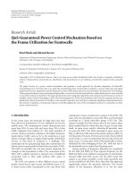
3.2. Flows of GPS Signal Detection Method w ith LE. Pro-
cedure of GPS signal acquisition based on LE can be
summarized as follows.
(1) Setting Threshold of f . Modify amplitude f of PEDF from
minute positive number to larger one smoothly and compute
corresponding LEs. When the larger one of two LEs most
approaches to zero from positive value, corresponding value
of f is threshold f
T
.
(2) Detectting Signal. Impose received data on oscillator
system. If the larger LE becomes negative, GPS signal at
frequency ω
G
is assured to be comprised in received data.
Operation flows in Figure 1 illustrate succinctly the
acquisition procedure.
4. Doppler and Code Phase Resolution
For implementation convenience in computer, (11)isrewrit-
ten in form of discrete time:
λ
i
p
i
=
lim
N →∞
1
N
N
k
log
A
(
k
)
p
i
. (12)
Time interval determines accuracy of LE. With fixed time
step, increasing N induces decrease in variance of calculated
LEs by ratio 1/N
2
.InfactN cannot approach infinity;
therefore the number N should selected at reasonable one.
Also, length of iteration step h affects accuracy of LE.
Ambiguity of LE increases when iteration step becomes
larger, and vice versa. Unfortunately, the iteration step
cannot be shortened arbitrarily considering convergence
and computation burden. Doppler resolution is affected by
accuracy of the LE number which is calculated at critical
state. Code phase resolution is determined by sampling
frequency [2]. Supposed that received data is sampled at
5 MHz in the front end, phase resolution of the oscillator
system is 0.1 microsecond.
5. Simulations
In simulation, Monte Carlo method is adopted to test
the performance of chaotic oscillator acquisition system.
As contrast, conventional acquisition methods are used in
simulation. GPS signal is based on signal model (6). Data
length of conventional algorithm is 0.4 second. Referring to
[2],GPSstrengthisatnominallevel
−130 dBm, and noise
level is
−174 dBm. From reference [4], GPS signal strength
indoors would decrease in the range from 15 dB to 30 dB.
Therefore, SNR of simulated indoor GPS signal ranges from
−49 dB to −34 dB, and CNR from 14 dBHz to 30 dBHz.
Threshold is chosen to allow one false alarm happens
among 10
6
times test on data without expected GPS signal.
As for alternate half-bit algorithm, the threshold used in
peak detection is 56; for differentially coherent acquisition
4 EURASIP Journal on Advances in Signal Processing
Initiate parameter
amplitude of PEDF f
= 0
Adopt Runge Kutta procedure;
iterate 5000 times, get sequence
of states
X
= x
0
, x
1
, , x
5000
Y = y
0
, y
1
, , y
5000
Compute LE
0 < larger LE < 0.001
f
= f +0.001
Ascertain threshold f
= f
T
Impose received signal U(t)
from front end
Larger LE < 0
GPS signal at frequency
ω
G
exists
GPS signal is
absent
Y
N
Y
N
Figure 1: Operation flows of Duffing oscillator acquisition system.
algorithm threshold is 50; for chaotic oscillator, threshold
value of LE is
−0.001 with 200 Hz Doppler resolution.
Damping coefficient k equals to 0.5. Initial state of (9)
is at point (0, 0, 0); iteration time step is 1/(1.25
× 10
6
× 10)
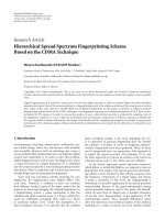
second. Figure 2 illustrates two LE curves versus amplitude
of periodic disturbing force f , and iteration step is Δ f
=
0.001. A key point that should be mentioned is that three-
stage autonomous system has three LE curves. The third LE
curve corresponding to time dimension is always zero, which
is neglected in Figure 2.
Figure 2 shows us that larger LE (upper curve)
approaches to zero when f equals to 0.829. So f
= 0.829
is selected as threshold f
T
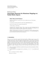
corresponding to critic state.
Figure 3 intuitively demonstrates phase plane at critic state.
With determined threshold f
T
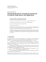
, impose data, which contains
expected GPS signal, on chaotic oscillator-based acquisition
system. The larger LE turns to be negative at the number -
0.169, which indicates big dimension circle state, as shown in
Figure 4.
To illustrate performance of the three algorithms, acqui-
sition probability curves are listed in Figure 5.
From Figure 5, chaotic oscillator system outperforms
other two conventional algorithms. Chaotic oscillator acqui-
sition algorithm approaches 1 detection ratio when CNR
is 19 dBHz; detection ratio is close to 0.9 when CNR
is 16 dBHz. However, to guarantee 0.9 detection ratio,
alternate half-bit method and differential coherent algorithm
demands for signal strength at 21 dBHz and 20 dBHz CNR,
respectively.
Lyapunov exponents
−0.6
−0.5
−0.4
−0.3
−0.2
−0.1
0
0.1
0.2
Amplitude of periodic disturbing force
0.60.65 0.70.75 0.80.85 0.90.95 1
Figure 2: Nonzero Lyapunov exponent curve via the f from 0.600
to 0.999.
6. Computation Burdern Considerasion
Computation burden is a key issue in GPS receiver design,
which affects tracking and decoding message.
In alternate half-bit method, received data is divided
into 10 milliseconds cells. Each cell correlates with locally
generated signal. FFT/IFFT is employed to implement fast
correlation. In the condition of 5 MHz sampling frequency,
numbers of real addition and real multiplication in each
EURASIP Journal on Advances in Signal Processing 5
y
−2
−1.5
−1
−0.5
0
0.5
1
1.5
2
x
−2 −1.5 −1 −0.50 0.511.52
Figure 3: Phase plane at critic state.
y
−2
−1.5
−1
−0.5
0
0.5
1
1.5
2
x
−2 −1.5 −1 −0.50 0.511.52
Figure 4: Phase plane at big dimension circle state.
Detection ratio
0
0.1
0.2
0.3
0.4
0.5
0.6
0.7
0.8
0.9
1
CNR (dBHz)
5 101520253035
Chaotic oscillator
Differential
Alternate half-bit
Figure 5: Acquisition probability curve: CNR from 5 dBHz to
35 dBHz.
cell are 3.12 × 10
6
and 0.781 × 10
6
,respectively.After
correlation, noncoherent calculation should be performed,
which needs 0.221
× 10
6
real additions and 0.142 × 10
6
real
multiplications. Therefore, to process 400-millisecond data,
31.2
× 10
6
real multiplications and 125 × 10
6
real additions
are needed.
In full-bit method, experimental data is divided into 20
groups. 20
×169 ×10
6
real addition and 20 ×43.9 ×10
6
real
multiplications are needed to deal with the 400 milliseconds
data. In fact, partial correlation can be used in accelerating
calculation, which will divide each group into equal sections.
If each section is at length 20 milliseconds, 20
× 135 × 10
6
real additions and 20 × 33.2 × 10
6
real multiplications are
needed totally.
As for differential coherent method, after correlation
between 1 milliseconds received data and local signal,
two adjacent correlation results perform conjugate multi-
plication. For 400-millisecond data, computation burden
is above 504
× 10
6
real additions and 186 × 10
6
real
multiplications.
As for Duffing oscillator, whole procedure is divided into
two parts. In the former part, the LE values in critical state
are computed. Afterwards, received data is taken as input to
test existence of expected signal. Suppose that iteration step
is 1/(1.25
× 10
6
× 10) in the whole acquisition procedure.
To determine threshold, state turns into critical one after
5000 times of iteration in simulation. After threshold deter-
mination, 10-millisecond data is taken as input of Duffing
oscillator system to test expected signal, which consumes
0.125
×10
6
times iteration. In each iteration, 76 real additions
and 102 real multiplications are needed. Therefore 9.51
×10
6
real additions and 12.8 ×10
6
real multiplications are needed
totally. Computation burden is reduced to one fiftieth of
conventional method.
7. Conclusions
In this paper chaotic oscillator is used to acquire weak
GPS signal. The suggested acquisition method belongs
to application of nonlinear dynamics which is different
from conventional method. LE is employed to determine
states of chaotic oscillator system. A procedure flow is
given to illustrate the acquisition method. The simula-
tion results demonstrate that chaotic oscillator acquisition
preponderates conventional ones. Chaotic oscillator can
detect signal at 16 dBHz CNR at detection ratio 0.9, with
false alarm ratio 10
−6
. Furthermore, oscillator acquisition
algorithm consumes much less acquisition time, which
is important for tacking signal and decoding navigation
message. The advantage derives from properties of nonlinear
dynamics.
Some other details in engineering have not been dis-
cussed in this paper. For example, in order to cover the
possible Doppler shift range 20 KHz [2], oscillator acquisi-
tion system can be implemented by parallel structure, with
multiple oscillator acquisition channels. Also, relationship
among threshold value of LE, undetected rate, and Doppler
resolution is another topic needed to be studied further.
6 EURASIP Journal on Advances in Signal Processing
Acknowledgment
Research work in the paper is supported by the National High
Technology Research and Development Program of China,
no. 2007AA12Z159
References
[1]J.J.SpilkerJr.,Digital Communication by Satellite, Prentice-
Hall, Englewood Cliffs, NJ, USA, 1977.
[2] J. B Y Tsui, Fundamental of Global Positioning System Receivers
a Software Approach, John Wiley & Sons, New York, NY, USA,
2004.
[3] D. M. Akos, P. L. Normark, J. T. Lee, K. G. Gromov, J. B Y.
Tsui, and J. Schamus, “Low power global navigation satellite
system(GNSS) signal detection and processing,” in Proceedings
of the International Technical Meeting of the Satellite Division of
the Institute of Navigation (ION GPS ’00), pp. 784–791, Salt
Lake City, Utah, USA, 2000.
[4]G.Lachapell,H.Kuusniemi,D.T.H.Dao,G.Macgougan,
and M. E. Cannon, “HSGPS signal analysis and performance
under various indoor conditions,” in Proceedings of the
International Technical Meeting of the Institute of Navigation
(GPS/GNSS ’03), pp. 1–14, Portland, Ore, USA, 2003.
[5] M. L. Psiaki, “Block acquisition of weak GPS signals in a
software receiver,” in Proceedings of the 14th International
Technical Meeting of the Satellite Division of the Institute of
Navigation (ION GPS ’01), pp. 2838–2850, Salt Lake City,
Utah, USA, 2001.
[6] H.Elders-BollandU.Dettmar,“Efficient differentially coher-
ent code/doppler acquisition of weak GPS signals,” in Proceed-
ings of the IEEE International Symposium on Spread Spectrum
Techniques and Applications (ISSSTA ’98), pp. 731–735, 2004.
[7]S.H.Strogatz,Nonlinear Dynamics and Chaos,Perseus
Publishing, LLC, Cambridge, Mass, USA, 2000.
[8] B. Le, Z. Liu, and T. Gu, “Chaotic oscillator and other
techniques for detection of weak signals,” IEICE Transactions
on Fundamentals of Electronics, Communications & Computer
Sciences, vol. E88-A, no. 10, pp. 2699–2701, 2005.
[9]D.Liu,H.Ren,L.Song,andH.Li,“Weaksignaldetection
based on chaotic oscillator,” in Proceedings of the IEEE 40th
Industry Applications Conference (IAS ’05), vol. 3, pp. 2054–
2058, Kowloon, Hong Kong, 2005.
[10] G. Wang, D. Chen, J. Lin, and X. Chen, “The application of
chaotic oscillators to weak signal detection,” IEEE Transactions
on Industrial Electronics, vol. 46, no. 2, pp. 440–444, 1999.
[11] P. Holmes, “A nonlinear oscillator with strange attractor,”
Philosophical Transactions of the Royal Society A, vol. 292, p.
419, 1979.
[12] M. T. Rosenstein, J. J. Collins, and C. J. de Luca, “A practical
method for calculating largest Lyapunov exponents from small
data sets,” Physica D, vol. 65, no. 1-2, pp. 117–134, 1993.