Development and Implementation of RFID Technology Part 14 pdf
Bạn đang xem bản rút gọn của tài liệu. Xem và tải ngay bản đầy đủ của tài liệu tại đây (5.29 MB, 30 trang )
RFID Information Value Chain and ETRI RFID Ecosystem: Value-added Environment
Linking Physical and Virtual Worlds
381
combined with different sources residing in the legacy system or external sources such as
purchased data services so that semantic events which are significant in the business
domain are generated. Here, the term “semantic event” means that, as it says, RFID data
capturing events merely indicate raw observation and taking business actions based only on
the event reports are somewhat limited; therefore, the raw observation events need to be
combined with additional business context information in order to construct business events
(here, we call ‘semantic event’) upon which legacy applications can play with. Furthermore,
the reason why this stage is required is to enable sophisticated RFID-based data processing.
As domain-specific information is integrated with RFID tag data, content-based filtering and
routing become possible by mapping and combining tag data with corresponding object
information and applying basic filtering scheme on the combined data.
In other way, Event-Condition-Action (or ECA) rules (Palmer, 2006) can be applied to
generate the semantic events. When a primitive tag data are delivered from the previous
stage as an event, the rule set associated with the event is evaluated and then appropriated
actions are taken. For example, ECA rule mechanism can be useful when predefined action
is taken by the comparison of the captured tag list with the scheduled information with little
human intervention. If the sensed tag list mismatches the schedule information, another
action to detect the problem can be taken. We may regard such the inference process as the
semantic event generation process making use of RFID tag data and additional information
stored in backend systems and supporting the conversion from raw RFID data to actionable
information.
3.5 Business process coordination
Main objective in the stage is to enable business processes and solutions to leverage the real-
time data captured by RFID infrastructure. The key benefit of RFID technology is automatic
identification of individual objects coupled with automatic data capture. The employment of
low-levels of process automation toward the process automation and efficiency
improvement ultimately leads to the high return in terms of efficiency and cost reduction.
3.6 Decision / actions
One of the desired advantages adopting RFID technology is real-time information gathering,
exchange and real-time item visibility. It means that real-time decision making could be
realizable. For example, real-time inventory monitoring suggests optimum reorder points
based on usage and improves inventory accuracy. Another purpose of this stage is to
provide guidance for action to decision maker based on the accumulated information and
ultimately produce the knowledge. As a lot of RFID data and related production
information are accumulated, it is possible to elicit the valuable knowledge from them – for
example, RFID data warehousing (Gonzalez et al., 2006). There are many methods to
produce guidance for decision maker and further knowledge as following:
Views of current or historical information. This is the simple approach and the modeling
usually consists of aggregation, summarization and filtering.
Forecast. This requires using a methodology like statistical regression based on the current
and historical information.
Recommendation of the best and alternative decisions. To find the best recommendation, an
optimization model searches among various alternatives and decides the best. Finding a
reorder point in inventory problem through various optimization techniques is an example.
Inference through data mining. This is the process to elicit knowledge by searching for the
pattern hidden within accumulated information.
Development and Implementation of RFID Technology
382
4. ETRI RFID ecosystem
ETRI RFID Ecosystem is an RFID software platform that supports not only the presented
capabilities that RFID middleware platform must provide but also the activities occurred on
RFID IVC, and ultimately provides the seamless environment spanning from the edge of the
enterprise network to the enterprise systems.
Figure 3 presents ETRI RFID Ecosystem in accordance with RFID IVC. ETRI RFID
Ecosystem is a multi-layered middleware platform in Java environment. The first layer –
RFID Event Management System (REMS
3
) – deals with primitive and compound event
processing in order to obtain purified and refined RFID event while having less business
context. The second layer – Real-time Business Process Triggering System (RBPTS) – is
responsible for generating the semantic business event by utilizing refined RFID event. On
the top layer, Orchestration Engine (OE) supports the autonomous business process
execution. The top layer deals with the generation of invaluable knowledge. Additionally,
Tagged Object Information Repository manages the tagged object information and makes
them available to whatever the information are required for the purpose of interoperability
and exchange within or among enterprises. It is designed to offer the seamless environment
extending from RFID hardware infrastructure to backend software systems, and support the
RFID IVC. In this section, we introduce the architectural considerations for RFID software
platform implementation (mainly, RFID middleware implementation), and then, the
functional features and the architecture of each individual that constitutes ETRI RFID
Ecosystem is discussed in the following.
Fig. 3. ETRI RFID Ecosystem and its Correspondence with RFID IVC.
3
ETRI REMS/EPCIS (including REMS) earned EPCglobal software certification
(ALE/EPCIS).
RFID Information Value Chain and ETRI RFID Ecosystem: Value-added Environment
Linking Physical and Virtual Worlds
383
4.1 Architectural considerations for RFID middleware platform
We discuss the several architectural issues and our concerns toward REMS, RFID
middleware since how well RFID middleware can perfom must be a decisive factor for
overall system performance of ETRI RFID Ecosystem. We here deliver our approach to meet
those requirements. There are several literatures which deal with concerns on RFID software
requirements (Luo et al, 2006; Floerkemeier et al., 2007). Especially, Luo et al. (2006)
proposed the following requirements for RFID middleware benchmarking: Streaming,
Reactivity (event triggering features) and Integration. In the next, we present how ETRI
RFID Ecosystem absorbs those requirements.
Component/Service-oriented Architecture
In general, many applications adopt the component or service-oriented frameworks – for
example, Spring Framework
4
- in order to enhance the system flexibility and reusability.
Among various component-based software architectures, we have chosen Avalon
framework (Loritsch, 2001; SourceForge Inc., 2008a) to implement the RFID middleware
servers. Using Avalon, it is straightforward to have the components of each server interact,
to instantiate different instances of the components, and to reuse code while having light-
weight and minimal features comparing with other application containers.
An Avalon applications, then, is composed of the Avalon infrastructure, the specified
components, and a ‘container’ that reads the configuration files and starts the process
running. The container reads the configuration files, loads the specified implementation
classes, and invokes the Avalon interfaces in order. In this implementation, we use Phoenix
(SourceForge Inc., 2008c) as a container.
Distributed System Architecture
The main role of RFID middleware is to filter and aggregate a lot amount of RFID tag events
coming from RFID readers. If the situation of the item-level RFID tags attachment on
individual items become realized in the near future, the single server which even equips
with high computational capabilities may not control a great amount of RFID tag reads
flowing into the system. Therefore, it is unlikely to handle a lot of data by a single server.
In this context, the term ‘distributed’ has somewhat different meaning from general sense.
For business applications in general, enterprise-scale business applications are distributed
and operated over the physically separated hardware in order to achieve the load balance
and increase scalability. In this sense, it is applicable to the RFID middleware software as
well. However, it has more than that: most of RFID readers can communicate with only one
system at a time. Therefore, if a reader is deployed into a RFID software, then no other
software except it can capture the tag reads by the reader. It implies that an application
which wants to utilize the tag reads by specific RFID reader must cooperate with the
software which have the connection with the reader.
In this implementation, we adopt the registry-based federated architecture. We name the
software system that offers the resource locator service as ‘Service Broker’. As shown in
Figure 4, Service Broker acts as a ‘federator’ and other subsystem including our edgewares
like ‘Reader Management Subsystem’ and ‘Event Management Subsystem’ are ‘federatees’.
When a subsystem connects into the network, it starts to send the predefined heartbeat
messages including the server name and IP over the network. When the Service Broker
4
Development and Implementation of RFID Technology
384
receives the message, it sends the acknowledge message back to the caller. If it is allowed to
join the federation, it sends the registration information including the server name, the
access information, and server type and so on, and asks for the download of common
resources like RFID reader adapters if necessary.
Fig. 4. Building Blocks for REMS, as a distributed system.
Reliability (Fault-Tolerant System Operation)
To ensure the reliable RFID data delivery to the desirable destinations, it is critical to
eliminate any single points of failure over all the layers. For example, Sun Java System RFID
Software (Gupta et al., 2004; Sun Microsystems Inc., 2006) adopts Jini technology (Sun
Microsystems Inc., 2008) for this purpose. When we consider our distributed RFID
middleware federation, there are three types of system failures that this RFID middleware
platform must take into account.
Failure of RFID readers The failure of any single RFID reader may link directly with the loss
of significant data in the business context. RFID middleware system only recognizes and
tracks items within range of readers and the failure of a reader may result in the data
missing for the items. To cope with this situation, our subsystem periodically checks the
aliveness of the connection with readers. If a reader stays unconnected in a pre-specified
period of time, the subsystem sends the failure notification by e-mail to the administrator in
order for him to examine the reader and periodically keeps trying to reconnect to the reader
until establishing the connection between the reader and the subsystem again.
Failure of the Individual Middleware Subsystem Each distributed subsystem may face the
system down because of several reasons – for example, the increase of system overhead
caused by the tremendous amount of data influx and failure of managing the system
overflow. To avoid the subsystem failure, we adopt a simple solution: that is for the service
broker acting as a control center to perform active monitoring, which consist of having
individual subsystems periodically send keep-alive messages to inform the service broker of
their aliveness. Thus, service broker always has an image about the health of their federation
over the network. If it has not received the keep-alive information from a subsystem for a
timeout, fault-detector module performs reachability test to the subsystem for conformation.
It is certain that it has a problem that it generates the amount of traffic; however, an
appropriate timeout period can be mediated with the consideration of the trade-off between
alleviation of network traffic and responsiveness of failure occurrence.
RFID Information Value Chain and ETRI RFID Ecosystem: Value-added Environment
Linking Physical and Virtual Worlds
385
When the service broker detects a subsystem’s failure, it sends the failure notification by e-
mail and then it packages all the operational resources related to the failed one and feeds
them to the temporal running server in order to take over all the responsibilities which the
failed subsystem has taken care of until then. At the startup stage of the service broker, the
temporal subsystem also starts up for this case. This approach can be possible because the
service broker keeps track of all the changes happened in the federation – that is, we adopt
the centralized meta-information sharing in order to cope with such failure.
Failure of Service Broker It is important to guarantee the stable running of the service broker
because it governs all the distributed individual subsystems as a control center. In order for
the safe operation, the service broker operates as a dual mode and the secondary service
broker maintains the redundant information with the primary one by periodically
replicating the information the primary manages so that it makes sure the continuous and
reliable operation of the service broker.
Various Passive/Active RFID Readers & External Sensors Support and their Management
RFID middleware should provide the means to handle the heterogeneity of RFID readers
in terms of the vendors and versions. Most RFID middleware software systems can
connect to the RFID devices via the reader adapters which play a role of managing
communication in a standardized way between the reader and the middleware. In the
implementation, eclipse-based adapter development toolkit is developed. Reader adapter
programmers can write java codes for the reader adapter which they want to provide
through this middleware and perform the Ant-based build process to generate the Jar
package. The adaptor is designed to be compatible with EPCglobal RFID Reader
Managment Protocol (EPCglobal, 2007a).
In addition, it is necessary to look at what custom configuration settings you may need to
tune on the reader that you choose. Currently, many middleware vendors support varying
levels of configuration on the RFID readers; however, some are limited in the amount of
control, which means that you are not able to control key settings such as antenna power or
antenna cycling. This may lead the users to manually configure the readers outside the
middleware if a tunable parameter is not supported. This manual tuning process may make
it difficult to manage the readers.
In order to alleviate such difficulties, we devise XML-based configuration for setting tunable
parameters for each reader as shown in Figure 5. The adapter programmers can decide the
scope of tunable parameters which are willing to be opened by simply exposing parameters
in the XML documents like Figure 5 (b).
Lastly, for the applications which do not necessarily require continous RFID reading
(Floerkemeier et al., 2007), it is preferable to have a mechnism to initiate tag reading by
external sensors. At this time, the reader adaptor can also cover the registration of external
sensors in the limited manner enough that the sensor-triggered RFID reader activation is
achievable.
Global RFID Standards Compatibility
There are several RFID-related global standards which RFID middleware must concern: (a)
interface between RFID tags and readers, (b) interface between RFID readers and host
applications and (c) information exchange interface between RFID middleware and RFID
applications.
Development and Implementation of RFID Technology
386
Fig. 5. Configuration for vendor-specific tunable parameters and commands: (a) XML
schema for configuring tunable parameters for reader setting and commands (upper), (b)
Example for Alien RFID reader
5
which is an instance of (a) (lower left), and (c) user interface
rendering from (b) (lower right).
Tag/Reader Interface (Air Interface Protocol): EPCglobal UHF RFID Class 0, Class 1 Gen 1, Class 1
Gen 2 Protocol and ISO/IEC 18000 series
RFID Tag/Reader interface defines the physical interactions between RFID tags and readers.
EPCglobal ratified the EPCglobal Class 1 Gen 2 protocol in 2004 and there are ISO 18000
series as a de jure air interface protocol standards in RFID system.
This interface has little concern with the RFID middleware implementation; however, it is
required to consider the tag memory structures described in those standard specifications.
The memory structure on the tags decides what types of information can flow in. Therefore,
this tag memory structure affects the reader/host protocol design, which subsequently has
an influence on the middleware implementation
Reader/Host Interface: EPCglobal Reader Protocol, Reader Management Protocol and ISO/IEC
15961, 15962
Reader/Host interface defines a set of commands for reader control, configuration and
management, tag reading and writing. Each RFID reader vendor defines its own
5
RFID Information Value Chain and ETRI RFID Ecosystem: Value-added Environment
Linking Physical and Virtual Worlds
387
reader/host protocol and some vendors provide libraries to help programmers to develop
RFID applications using their RFID readers in more convenient way. As part of resolving
the diversities of reader/host protocol varying from vendors, the demand for developing
general reader/host protocol leads to the development of EPCglobal Reader Protocol, and
ISO/IEC 15961 and 15962. But, two protocols have different operations to have access to tag
data due to the difference of tag memory structure and data organization in it. However,
they define the general features which most RFID reader vendors also take into
consideration, so most vendor-specific reader/host protocols can converge on either
protocol.
When it comes to the middleware implementation, it is important to support as many
market-available RFID readers as it can. Most middleware vendors provide toolkits to
develop so-called ‘reader adapter’, which is a driver-like pieces that interfaces to actual
RFID reader and provides a unified interface for RFID middleware to have access to readers.
We also take the same approach to support various types of readers and devise the vendor-
neutral reader/host API set in order to have access to those readers in a seamless way. The
two global standard specifications play a critical role of deriving the common API set for the
reader adapter while satisfying the diversities of vendor-specific protocols.
Middleware/Application Interface: EPCglobal Application Level Events
Application Level Events (ALE) is a software specification for the filtering and collection of
RFID data being defined and ratified by EPCglobal. It defines a globally accepted method of
filtering and collecting RFID information and it is the most representative standard interface
between RFID middleware and external applications. As a result, this standard is expected
to improve the interoperability between systems as it becomes widely accepted, so it is
necessary to develop the middleware software that complies with this EPCglobal mandates,
ALE. We fully implement ALE 1.0 (EPCglobal, 2005b) and currently extend it to meet ALE
1.1 (EPCglobal, 2008a) while reflecting ISO active tag features.
Application Integration
The ability to integrate RFID into the legacy systems or existing ones is absolutely critical
to deliver the sensed tag events to the right applications in the right time. The simple
approach is just to dispatch the captured events from readers to a series of applications at
the low level; whereas, some form of enterprise application integration (EAI) is needed to
get the full value from RFID events. Many major EAI solution providers like ‘Tibco’ try to
integrate their solutions with RFID middleware and release to the market (Tibco Software
Inc., 2006).
In particular, it is necessary to support various types of application integration methods
including push, pull and publish/subscribe for application-level RFID information capture. For
this, we take the following approach: our middleware is equipped with several standards-
based adapters required to ensure connectivity to backend applications. In addition, it is
necessary to allow application developers to register their own adapters to send the filtered
RFID events to their legacy applications. In this implementation, there are six different
protocols in order to let legacy applications receive the notification of RFID event messages
– that is, HTTP, TCP/IP, JMS, File and Web Service (SOAP/HTTP). Users can subscribe to
the middleware by entering URIs with specifying the protocol. Table 1 shows how to specify
URI for each protocol.
Development and Implementation of RFID Technology
388
Protocol URI Template Example
HTTP
http://<ip>:<port>/<web
page>?pollingInterval=<millisecond>
http://129.254.238.16:8080/reports_l
og.jsp?pollingInterval=50000
TCP/IP tcp://<ip>:<port> tcp://129.254.238.16:7000
JMS
jms://<queue|topic>/<JMS Connection
Factory>/<queue|topic name>?
jndiInitialContextFactory=<Java class
URI for JMS context factory}
&jmsProviderURL=<URL of JMS
Provider>
jms://topic/JmsTopicConnectionFac
tory/triggerTopic?jndiInitialContext
Factory=org.exolab.jms.jndi.InitialCo
ntextFactory&jmsProviderURL=rmi:
//localhost:1099
File
file:///<directory>:/${SpecName}_${yy
yy
MMddhhmmss}.xml
file:///c:/sample_${SpecName}_${y
yyyMMddhhmm}.xml
Web
Service
axis://<end-point address>?
optQName=<Operation QName>
&optServiceName=<Service Name>
axis://localhost:8080/ECReportsSer
vice.asmx?optQName=escape(‘http:/
/www.etri.re.kr’)&optServiceName=
OperationProcess
Table 1. URI definitions and their examples for RFID event subscription
Moreover, application programmers can develop their own event dispatch modules
inheriting from designated Java interface we suggest and deploy them into the system in
order to ensure the application-dependent protocol-based communication between the RFID
middleware and their legacy applications.
4.2 ETRI RFID event management system (ETRI REMS)
RFID middleware is a software system that manages data communication between RFID
readers and enterprise applications. In this section, we present the layered RFID
middleware while considering architectural design aspects discussed in the previous
section. We divide the RFID middleware into three layers – that is, ‘device monitoring and
management layer’, ‘data management layer’ and ‘business integration layer’. As given in
Figure 6, the ETRI RFID middleware covers lower two layers and consists of two
subsystems: Reader Device Abstraction & Management Subsystem for device monitoring,
Event Management Subsystem for RFID data management and delivery. Also, there exists
Service Broker for offering the name lookup service and resource sharing. The functional
features and internal component architecture of each subsystem are described in the
following.
Reader Device Abstraction and Management Subsystem (RMS)
The primary roles of RMS are to support the seamless integration between the middleware
software and various kinds of RFID readers, and to monitor and manage the deployed
readers. In order to handle the heterogeneity of readers and reader/host interface protocols,
we abstract the reader/host interface APIs with help of the existing global reader/host
interface standards mentioned in Section 4.1 and offer the eclipse
6
-based development
toolkit for ‘reader adapter’. Single reader adapter is developed per each vendor and version
6
RFID Information Value Chain and ETRI RFID Ecosystem: Value-added Environment
Linking Physical and Virtual Worlds
389
Fig. 6. Layered conceptual architecture of ETRI REMS.
if the vendor does not guarantee the backward compatibility of reader/host interface.
Moreover, reader adapter developers take a responsibility of organizing the tunable reader-
specific parameters by editing XML file shown in Figure 5 and implementing the proper
execution codes for them. Those activities improve the extensibility for newly-introduced
RFID readers at this middleware system.
In Figure 7(a), we show the component architecture of RMS using Avalon and the
dependencies among the components. All the components are deployed and controlled by
Phoenix. As shown in the Figure 7(a), there are three major components: Connection
Manager, Monitor and Reader Agent Manager with Reader Agent.
Fig. 7. Reader Device Abstraction & Management Subsystem: (a) component architecture
(left) and (b) main user interface for reader configuration and monitoring (right).
Development and Implementation of RFID Technology
390
The task of Connection Manager is to manage all the context information related to the
deployed RFID readers and issue commands for reader management. All the commands
exposed at the user interface are sent to this component. Then, this component validates and
dispatches them to appropriate other components. The Monitor is responsible for
monitoring the events occurred in the system. For example, it keeps track of the aliveness of
individual active readers and notifies the erroneous events to the administrator or the reader
management user interface in Figure 7(b).
The task of Reader Agent Manager is to manage the life cycle of Reader Agents representing
the actively connected RFID reader or external sensors, and act like a container for Reader
Agents. In general, a Reader Agent binds with a physical reader and handles all activities
related with corresponding reader such as sending commands to a reader to control the
reader and receiving tag data. Besides the reader-specific tunable parameter setting, each
Reader Agent provides the following operations: (a) connect/disconnect reader, (b)
suspend/resume reading tags (c) modify Reader Agent information, (d) delete Reader
Agent and so on.
In addition, Reader Agent Manager has a dependency with Scheduler, Quartz, which is
java-based open source scheduler. Basically, Reader Agent operates in a polling manner as a
default operation mode in order to capture tag data in a reading zone; however, our
implementation allows it to operate in the on-demand mode or user-specified schedule-
based mode. For the latter case, the administrator specifies the Unix crontab-like expression
with duration and Quartz scheduler awakes the Reader Agent based on the crontab
expression and let it collect tag reads for the duration.
RFID Event Management Subsystem (EMS)
EMS is the core system in this middleware platform which filters data extracted from the
RFID readers, aggregates the information and routes the data to the RFID-enabled
applications (see Figure 8).
Fig. 8. Conceptual Representation of RFID Event Management Subsystem (EMS).
EMS enables ALE-based event queries and customizable event stream processing
operations. Such the processes allow raw RFID data to be transformed into business
information that can be leveraged by RFID-enabled external applications. In order to
support reliable event processing and better performance, EMS adopts pipeline architecture
as a basis for data processing. A pipeline consists of a set of primitive task processors called
‘valves’ and ‘chain’s connecting two valves. Pipelines categorize the influx data and process
RFID Information Value Chain and ETRI RFID Ecosystem: Value-added Environment
Linking Physical and Virtual Worlds
391
those categories with a set of primitive tasks. By following the ‘divide-and-conquer’ like
approach, it is expected to increase overall throughput and the average speed for high-
volume data processing. Moreover, the XML-based event description named ‘ECSpec’ in
ALE specification can be expressed in a pipeline way, so we stack ALE-specific processing
modules over the pipeline-based processing modules in order to support ALE API as shown
in Figure 9(a).
Fig. 9. Event Management Subsystem: (a) component architecture using Avalon (upper), (b)
pipeline designer (lower left) and (c) ALE ECSpec designer and monitor (lower right).
Figure 9(a) shows the component architecture of EMS using Avalon and the dependencies
among the components. As stated above, the building blocks for pipeline support reside in
the bottom layer, followed by ALE-specific components. The major components are Valve
Information Manager, Pipeline Execution Manager and ECSpec Worker Manager. Valve
Information Manager is responsible for managing built-in or custom event processors.
Development and Implementation of RFID Technology
392
Application programmers can create custom event processing valves as well as event
dispatchers which pre-process filtered RFID data prior to propagating the information to
external applications and use them while building up the event stream processing pipeline.
The task of Pipeline Execution Manager is to control the execution of pipelines and exception
handling. We provide the user interface to define a pipeline instance as shown in Figure 9(b).
ECSpec Worker Manager takes a role of managing individual ECSpec Worker per each
ECSpec given by outers. When the request for ECSpec is received, the ECSpec Worker
Manager parses the request described in XML, transforms it into a pipeline and then asks
Pipeline Execution Manager to execute the pipeline. The pipeline instance is linked with an
ECSpec Worker internally so that the result of event processing by the pipeline is at first
delivered to the ECSpec Worker. The role of ECSpec Worker is to manage the information of
subscribers to the related ECSpec and handles the pipeline executions. Figure 9(c) shows the
administration user interface for defining and monitoring ECSpec.
Lastly, we deploy the lightweight web server, Jetty (Mort Bay Consulting, 2008), with Axis
in order to support the Web Service ALE API.
Service Broker
The Service Broker plays a role of a control center over the distributed network discussed in
Section 4.1. It keeps track of the all the distributed subsystems and provides the name look-
up service for them – especially, our user interface uses this look-up service to have access to
individual subsystem.
Another major role of this service broker is to configure the logical readers. Generally, a
single reader is not often sufficient to reliably cover the entire physical area relevant to a
business process. For example, a loading dock may have to be equipped with several
readers that should be exposed to client applications as a single logical reader. This enables
EMSs to avoid the modifications from the change of readers in RMSs. Service broker offers
methods to configure the logical readers and the relations between a logical reader and
physical readers deployed to RMSs.
Fig. 10. Component Architecture of Service Broker.
Figure 10 shows the component architecture of Service Broker. We develop the Java servlet
pseudo-container for Avalon components in order to reuse components we already
RFID Information Value Chain and ETRI RFID Ecosystem: Value-added Environment
Linking Physical and Virtual Worlds
393
developed and keep consistency with other systems. As major components, Naming Service
Manager maintains distributed system configuration information such as access information
of all RMSs and EMSs. Heartbeat Message Monitor and Fault-Detector keep track of the
aliveness of all subsystems and take reactions whenever any failure of them is captured. The
task of Logical Reader Information Manager is to maintain the configuration of logical
readers and the relations between logical readers and physical readers.
4.3 Real-time Business Process Triggering System (RBPTS)
Real-time Business Process Triggering System (RBPTS) is built on a rule-based inference
engine which provides mechanism to extract semantic and business-context information
from tag read events through ECA-type rules. Such semantic information is derived from
domain-specific knowledge provided by domain experts or business collaboration partners
and embedded in rule definitions. The semantic events – as discussed in Section 3.4 – are
produced by associating the RFID primitive events with the domain-specific information
residing in legacy system. This system receives a continuous stream of filtered and
unfiltered RFID data from RFID middleware or RFID readers and produces the RFID-
triggered business event by using set of rules. The produced semantic event is utilized for
the query to execute collection of rules to perform various predefined actions ranging from
one-time actions such as DB operation, the notification, alerts, actuator operations, or actions
that involve the long term business process actions which require interoperation with
workflow systems such as ebXML
7
engine and BPEL
8
-based workflow engine. The
development of RBPTS is driven by the requirement of flexible way of incorporating RFID
data with business applications; that is, to convert the data from lower RFID middleware
layers to actionable semantic information for the upper layers.
In order to achieve the goal and be suitable for RFID environment, the rule engine of RBPTS
adopts the backward chaining inference mechanism. As the physical RFID readers involve
the specific business goals – for example, gate open/close, inventory check and so on – and
the business actions triggered by the collected data fall into small number of categories, it is
expected that possible conclusions can be chosen at the time that a set of tag data is collected
by specified readers. The domain experts define a set of rules which are described as the ‘If-
condition(s)-then-action’ pattern. The event message delivered by REMS includes the
‘action’ indicator called ‘query’ to be proved, so the inference process starts with a
conclusion with the help of ‘query’. The rule engine searches for the rule set which has the
action clause that matches the action which the event message includes and then evaluate
the associated condition clauses. The condition is described as not just a simple form like
value matching but also complicated form like a predefined java class or access to database
located in the legacy system.
Figure 11 shows the RBPTS components and the internal message flow. We note that we
revised the open source java class library, MANDARAX (SourceForge Inc., 2008b), in order
to implement ECA-type rule engine, and XML Schema for ECA rule definition is newly
defined as presented in Figure 12.
7
8
Development and Implementation of RFID Technology
394
Fig. 11. Architecture of Real-time Business Process Triggering System and Sample Event
XML Message over SOAP/HTTP delivered from REMS.
Fig. 12. XML Schema of Rule Definition.
REMS accumulates RFID tag data over intervals of time, filters to eliminate duplicate tag
data and the tag data that are not of interest, and then reports in the XML/SOAP message
form which follows the input format of RBPTS (see Figure 11). The RBPTS-specific event
XML messages are generated by custom message dispatcher registered in REMS. RFID
Event Report Handler accepts the SOAP message and then passes it to Event Manager in
turn. Event Manager unmarshals the event message, checks whether the message is valid by
looking up the event registry and checking its register status. Afterward, Event Manager
reorganizes the valid event message into sort of event query message that is used for the
next step - inference process - and delivers it to Rule Manager. Rule Manager inquires for
the rule set associated with the event query and constitutes all the matters that are essential
for the reasoning: database drivers that have access to the legacy database, repository
RFID Information Value Chain and ETRI RFID Ecosystem: Value-added Environment
Linking Physical and Virtual Worlds
395
information and so on. Rule Manager feeds all the prepared materials into the Inference
Engine and then this evaluates the conditions for each rule and generates the result set. This
is during the process that business semantics are disclosed. Types of conditions span from
simple forms including direct comparison to more complex ones such as inquiring to
external applications. Based on the result set, Rule Manager organizes the action execution
list and passes the list to Action Manager. Action Manager searches for the web service for
each action execution and configures the information for the web service call. Action
Manager asks for Web Service Agent to call the dynamic web service and records the
execution result on the log database. RBPTS supports the application triggering via web
service only.
In addition, RBPTS provides web-based user interface for rule design to model RFID event,
related business rules and the detailed actions which in result provide more flexible way to
adapt to the rapidly changing business environment.
4.4 Orchestration Engine (OE)
To build a concrete RFID middleware platform, it is desirable to orchestrate RFID-based
end-to-end processes that associate with multiple applications or legacy systems so that it
ultimately provides the RFID-enabled process automation environment.
Fig. 13. Architecture of Orchestration Engine (OE) and GUI Window of OE Administrator.
For this purpose, the business process/workflow coordination engine called ‘Orchestration
Engine’ is developed and the system architecture is shown in Figure 13. Currently, the most
recent answer to the integration challenge is the Service Oriented Architecture (SOA) and
the Web Service technologies. We suppose that we can access different functionalities of
different legacy and other developed applications in a standard way through Web Services.
Under the environment that all applications expose the functionalities via Web Services, we
develop a business process definition and execution engine that provides a way to compose
the Web Service-exposed functionalities in J2EE framework. Mostly, the business processes
defined by Orchestration Engine are triggered by RFID-related events including not only the
primitive event as the output of data transformation on the RFID IVC but also the semantic
event generated by RBPTS.
In this implementation, we adopt BPEL (Business Process Execution Language for Web
Services) (Andrews et al., 2003), an XML-based industry standard for business process
management, as the definition language of business processes. BPEL builds on top of XML
and Web Services, and BPEL process specifies the exact order in which participating Web
Development and Implementation of RFID Technology
396
Services should be invoked. As the typical scenario we develop under the ETRI RFID
Ecosystem, a BPEL business process receives a SOAP request from RBPTS when the raw
observation by REMS are dispatched to RBPTS with XML event message and the rule
instance, which is invoked by the message and contains the action clause of calling the BPEL
process, is evaluated as true. Then, new instance is started and managed by Process
Manager. It calls the external Web Services specified in the BPEL definition – for example,
invoking EPCIS Web Service in order to get the prices of products and then invoking
calculator Web Service to sum up the prices of items which are checked out – and returns
the results when the process instance is done.
7. Conclusion
One of major issues in RFID software platform is how to (i) handle vast amount of RFID
data efficiently and (ii) transform raw RFID tags to more valuable forms so that RFID-driven
business applications can create value and achieve their ideal goals – automated business
execution and integration. In this chapter, we introduce the concept of RFID Information
Value Chain (RFID IVC), sequential activities for RFID data semantics evolution and value
creation, and then discuss the several architectural considerations when we developed our
RFID software platform called ‘ETRI RFID Ecosystem ’, whose middleware has features of
component-oriented architecture, distributed and reliable operations, support of various
types of RFID devices including external sensors, compatibility with existing RFID
standards and business applications integration. We believe that we address the majority of
the RFID software implementation concerns which other products should regard.
In addition, we demonstrate the RFID software platform with the internal service
component architecture and the dependencies among components. It is presented how the
discussed architectural considerations have been applied in order to construct such the
RFID middleware. In fact, this artifact was tested in the field of several RFID pilot projects in
South Korea including yard management project in harbour (Kim et al., 2006) and it showed
the competitive advantages of ETRI RFID Ecosystem in the sense of the improvement in
operational efficiency rather than partial deployment as desired.
8. References
Andrews, T., Curbera, F., Dholakia, H., Goland, Y., Klein, J. Leymann, F., Liu, K., Roller, D.,
Smith, D., Thatte, S., Trickovic, I. & Weerawaran, S. (2003). Business Process
Execution Language for Web Services version 1.1.
/>bpel.pdf
Clark, S., Traub, K., Anarkat, D. & Osinski, T. (2003). Auto-ID Savant Specification 1.0, MIT
Auto-ID Center working paper
Dutta, K., Ramamritham, K., Karthik, B. & Laddhad, K. (2007). Real-time Event Handling in
an RFID Middleware System, Proceedings of Workshop on Databases in Networked
Information Systems, pp. 232-251, ISBN 978-3-540-75511-1, Japan, October 2007,
Springer
EPCglobal (2005a). EPC Radio-Frequency Identity Protocols Class-1 Generation-2 UHF RFID
Protocol for Communications at 860 MHz – 960 MHz Version 1.0.9.
RFID Information Value Chain and ETRI RFID Ecosystem: Value-added Environment
Linking Physical and Virtual Worlds
397
EPCglobal (2005b). The Application Level Events (ALE) Specification, Version 1.0.
EPCglobal (2006). Reader Protocol Standard, Version 1.1.
EPCglobal (2007a). Reader Management 1.0.1.
EPCglobal (2007b). EPC Information Services (EPCIS) Version 1.0, Specification.
EPCglobal (2008a). The Application Level Events (ALE) Specification, Version 1.1.
EPCglobal (2008b). EPCglobal Object Name Service (ONS) 1.0.1.
Floerkemeier, C., Roduner, C. & Lampe, M. (2007). RFID Application Development With the
Accada Middleware Platform. IEEE Systems Journal, Vol. 1, No. 2, December 2007,
pp. 82-94
Gonzalez, H., Han, J., Li, X. & Klabjan, D. (2006). Warehousing and Analyzing Massive RFID
Data Sets, Proceedings of the 22nd International Conference on Data Engineering, pp. 83-
92, ISBN 0-7695-2570-9, Atlanta, USA, April 2006, IEEE Computer Society, USA
Gupta, A. & Srivastava, M. (2004). Developing Auto-ID Solutions using Sun Java System
RFID Software.
/rfid/sjsrfid/RFID.html
IBM. (2006). IBM WebSphere RFID Handbook: A Solution Guide.
ISO/IEC JT1/SC31/WG4.
Kim, Y., Yoo, J. & Park, N. (2006). RFID Based Business Process Automation for Harbor
Operations in Container Depot, Proceedings of Industrial & Manufacturing
Engineering Graduate Research Symposium at Wayne State University, pp. 213-226,
Detroit, USA, April 2006
Ku, T., Zhu, Y. & Hu, K. (2007). Semantics-based Complex Event Processing for RFID Data
Streams, Proceedings of First International Symposium on Data, Privacy and E-
Commerce, pp. 32-34, ISBN 978-0-7695-3016-1, Chungdu, China, November 2007,
IEEE Computer Society, USA
Loritsch, B. (2001). Developing with Apache Avalon. Apache Software Foundation
Luo, Z., Wong, E., Cheung, S.C., Lionel, M. & Chan, W.K. (2006). RFID Middleware
Benchmarking, Proceedings of the 3
rd
RFID Academic Convocation, Shanghai, China,
October 2006
Mort Bay Consulting. (2008). Jetty – Java HTTP Servlet Server.
/jetty/.
Oracle. (2008). Oracle RFID and Sensor-based Services.
/rfid/index.html
Oat Systems & MIT Auto-ID Center. (2002). The Savant Version 0.1 Alpha, MIT Auto-ID
Center Technical Manual
Palmer, M. (2006). RFID and Complex Event Processing, RFID Today,
Sarma, S.; Brock, D.L. & Ashton, K. (2001). The networked physical world proposals for
engineering the next generation computing, commerce & automatic-identification.
MIT Auto-ID Center white paper
Development and Implementation of RFID Technology
398
Sun Microsystems Inc. (2006). Sun Java System RFID Software 3.0 Developer's Guide.
Sun Microsystems Inc. (2008). Jini Network Technology.
SourceForge Inc. (2008a). Avalon – Framework branch.
/avalon/?branch_id=18263
SourceForge Inc. (2008b). Mandarax Project.
Tibco Software Inc. (2006). RFID Solution.
/biztech/rfid.jsp
21
Enhancing the Interactivity
of Learning-Guide Systems with RFID
Yo-Ping Huang
1
, Yueh-Tsun Chang
2
, Wei-Po Chuang
2
and Frode Eika Sandnes
3
1
Department of Electrical Engineering, National Taipei University of Technology,
2
Department of Computer Science and Engineering, Tatung University,
3
Faculty of Engineering, Oslo University College,
1,2
Taiwan
3
Norway
1. Introduction
Many countries, including Taiwan, have over the last few years been actively promoting
digital archives programs. Recent advances in information science and computer technology
has opened up novel new means in which the general public can enjoy and be educated on
historical and cultural relics that are important parts of a country’s national heritage. New
technologies has led to a growing number of extensive digital databases for artifacts such as
pictures and visual art, writings, records, and other cultural objects. Researchers have
therefore started to explore new ways in which these digital databases can be associated
with the actual relics such that the knowledge and understanding of these objects can
become more accessible to the general public.
Currently, many exhibition centers employ professional guides that explain the objects on
display, answer questions and provide guided tours. Although such services are effective,
pedagogic and promoting social interaction, it is limited by the human resources available
and is therefore usually offered during peak hours and for groups with a minimum number
of participants. Exhibition centers and museums therefore often provide self-service
prerecorded audio guides to increase accessibility. Visitors carry portable audio players, on
loan from the museum, and listen to the prerecorded guide through headsets as they walk
through the exhibition. Such guides usually provide sufficient information about the objects
on display. However, the static nature of the prerecorded guided tours means that the
visitors need to view the exhibitions in a particular order and this restriction leaves little
room for visitor participation and interaction [3]. Furthermore, visitors have different
expectations and interests, and some visitors may be too impatient to complete their tours.
Some museums employ digital audio devices that allow the users to enter a set of digits
matching digits displayed next to an artifact. This allows users to manually control the
playback order. More advanced audio guides have been proposed, such as Sotto Voce [21],
which promotes social interaction where visitors eavesdrop others’ personal audio guide.
This study targets indoor guides, as outdoor guides pose different challenges [20, 23].
Development and Implementation of RFID Technology
400
Radio Frequency Identification (RFID) is a wireless communication technology that has
been successfully applied to various fields such as transportation, distribution, supply chain,
telemedicine, etc. RFID technology was used during World War II to identify airplanes as
friend or foe, but was then forgotten for many years. Because the electronic tags have been
expensive, RFID technology has not until recently become widely embraced. In 2003, Wal-
Mart, the leader of retail business in United States started using RFID technology and
incorporated an extensive RFID system in their storehouse and circulation. This event was
picked up by others resulting in the RFID market rising rapidly and catching wide attention.
The price of electronic tags is decreasing, and the RFID technology is now widely applicable
and about to become acceptable for all kinds of fields.
RFID systems can be classified as non-contact and automatic identification technology that
consists of two components – RFID readers (also called interrogators) and electronic tags
(also called transponders). Unlike traditional bar-code system, RFID systems can carry
dynamic as well as static data. According to different kinds of electronic tags, the
functionality and memory size vary. Traditional bar-codes are reliant on an unobstructed
label face of the codes because they need to be scanned to identify the digital data, and it
takes a while to identify the traditional bar-codes. On the other hand, with RFID systems,
tags can be hidden and there is no need to pay attention to the label face. As long as the tags
are in the range of the radio wave that the RFID reader sends out, the information in the tags
can be accessed and identified, and they can be identified rapidly through the radio wave. If
there is more than one item, traditional bar-code must be scanned sequentially. In contrast,
multiple tags can be read simultaneously.
We propose a novel interactive mobile guiding environment, where PDA’s and both UHF
and HF RFID technologies [6] are used to overcome the static nature of prerecorded guides
and the code-entry effort of older interactive digital audio guides. In addition, the
interactive learning infrastructure includes a wireless network and the system makes use of
data mining and information retrieval technology [4]. The combination of RFID and wireless
connectivity also allow remembering tools [22] to be realized such that visitors can review
their visit remotely via the web at a later time. The proposed system allows an art museum
to provide all its related artifact data or questionnaires to the visitors by equipping each
artifact with an electronic tag. The long-distance RFID reader allows art galleries to promote
exhibitions and attract visitors to the “hidden treasures” of less popular areas [8]. The
system also recommends viewing routes for visitors. These recommendations are obtained
by performing Apriori-like collaborative filtering on the individual viewing records [13, 14].
Our system is different to previous RFID-based guide systems [16, 17, 24] as two separate
RFID systems that employ the HF and the UHF frequency bands respectively are used in
parallel. The HF RFID system is used to increase personalization service and to attract
visitors to specific artifacts [9]. The visitors do not have to wait long for the system to
respond once they approach the target artifact as the HF tag instantaneously communicates
with the system such that the related information is provided to the visitors without
intervention [5, 11]. The long-distance UHF RFID reader, positioned at a strategic location
within the museum, reads the UHF tag attached to the PDA of the visitors and is used to
promote less-known artifacts.
The HF frequency band RFID system is based on ISO 15693 passive electronic tags, RFID
readers and middleware. The passive ISO 15693 tags are not reliant on power.
Consequently, there is a limited transmission distance, which makes them readable within a
Enhancing the Interactivity of Learning-Guide Systems with RFID
401
given radius of an artifact. Furthermore, passive tags are especially suitable for exhibitions
because of their ubiquitous attributes – namely, compact size, long life, no need for
maintenance, and low cost [12].
Visitors’ PDAs are equipped with electronic EPC class 1 UHF tags. UHF frequency band
RFID readers are installed at strategic locations throughout the exhibition venue. These are
typically locations that receive fewer visitors and need to be actively promoted. Information
read from an EPC class 1 electronic tag, attached to a visitor PDA, is immediately
transmitted to the server middleware. Next, the middleware determines which visitor the
tag belongs to and then delivers promotional information about the given exhibition via the
wireless network to the visitors’ PDAs.
2. Exhibition recommendation
The exhibition centers generally group artworks according to themes or type, such as
photographs or Chinese ink-water paintings, in different sections. Occasionally, artworks
are put together for a particular artist for his/her commemoration or to present a
retrospective angle of the artist.
Data mining is an emerging technology that extracts useful information or patterns from
large databases, data warehouses or other storage repositories. Data mining is also a field
bringing together techniques from machine learning, pattern recognition, statistics,
databases, and visualization, etc.
2.1 Mining association rules
Association analysis involves finding association rules from data stored in databases.
Association rules relate the associations of attribute-value frequently appearing in the given
dataset. A traditional example of association rule mining is the market basket analysis. The
process finds associations from grocery selection of a customer in the basket and then
discovers the purchase behavior of customer.
Normally, two steps are required to extract the association rules from databases.
1. Find the sets of large itemsets: The first step is to find all the itemsets and supports of
these itemsets must be larger than a predefined minimum support (threshold). The
minimum support is usually defined by domain experts and is case dependent.
2. Generate strong association rules from large itmesets: By applying both support and
confidence values to the large itemsets, strong association rules can be solicited. For
example, the rule “item_C
⇒ item_D [support = 25%, confidence = 50%]” means that 25%
of transactions show that both item_C and item_D were bought together, and there are
50% of chance that if people bought item_C then they will buy item_D too.
The Apriori algorithm [14] can be applied to get large inter-itemsets. However, the
processing cost of the first two iterations (i.e., obtaining L
1
and L
2
, representing large 1-
itemset and large 2-itemset, respectively) dominates the total mining cost. The reason is that
a low minimum support induces a very large L
1
, which in turn results in a huge number of
itemsets in C
2
(i.e., candidate 2-itemset). This problem is even more severe when mining
inter-transaction association rules. Tung et al. proposed the FITI algorithm that first finds
the frequent intra-transaction itemsets and then generates the inter-transaction itemsets
from the frequent intra-transaction itemsets. The work reduces the number of candidates
and therefore improves the mining efficiency [25]. Lu et al. employed EH-Apriori to reduce
Development and Implementation of RFID Technology
402
the number of candidate inter-itemsets [26]. Pei et al. [27] employed a projection scheme in
the PrefixSpan algorithm where the customer sequences (transactions) were projected into
overlapping sets called projected databases such that all the customer sequences in each set
have the same prefix that corresponds to a frequent sequence (itemset). The underlying
principle of the PrefixSpan is that, instead of projecting sequence databases by considering
all the possible occurrences of frequent subsequences, the projection is only based on the
frequent prefixes. This holds because any frequent subsequence can always be found by
growing a frequent prefix. The advantages of the PrefixSpan algorithm are (1) no candidate
sequence needs to be generated; and (2) the projected databases shrink [27].
The visitors’ viewing history is continuously recorded as visitors browse the exhibition
using the mobile guiding system. Information stored in the database includes timestamps
for the various viewing events, the particular contents viewed, and the details browsed for
particular artifacts [14]. Once a substantial amount of data has been collected a data mining
algorithm is used to discover association rules between artifacts and the artists. These
association rules are subsequently used to suggest useful exhibition-related information to
future visitors. For example, assume the system generates an association rule as follows:
If “Little Flying Phoenix (Sculpture, Yang Yuyu)” and “Suckling Lamb (Sculpture, Ju
Ming),” then “Field Laboring (Print, Yang Yuyu).”
Then, if a visitor inquires information about the ‘Little Flying Phoenix’ by Yang Yuyu and
the ‘Suckling Lamb’ by Ju Ming, the system automatically recommends the information
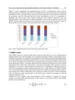
about the ‘Field Laboring’ by Yang Yuyu to the visitor as shown in Figure 1(a).
(a) The user can select different
recommendation modes.
(b) The other recommendation mode.
Fig. 1. Exhibition recommendation.
2.2 Collaborative filtering
Information about visitors is used to perform collaborative filtering [2]. Recommendations
are created according to groups of visitors with similar and related interests and preference.
Enhancing the Interactivity of Learning-Guide Systems with RFID
403
Item-based filtering is a strategy where the connection between items is identified according
to visitors’ selections, preferences, and browsing patterns. This technique is commonly
employed on e-commerce web sites where, for example, warehouse retailers collect
information about products purchased by customers. Next, the connection between
purchased products and customers’ purchasing habits are then estimated. Finally, the
warehouse retailers can recommend additional and relevant products when the customer
purchases certain items.
Big Pot Square Dish Revolve Soul-box II Moon Bowl
Visitor A 1 1 0 0 1
Visitor B 0 1 0 1 1
Visitor C 0 0 1 0 0
Visitor D 1 1 0 0 0
Visitor E 1 0 0 1 0
Table 1. Collaborative filtering example.
Table 1 shows an example of collaborative filtering where artifacts viewed by a visitor are
assigned 1 and artifacts that are not visited are assigned 0. In this example, the viewing
patterns of visitor A and visitor D have the highest similarity. Therefore, artifacts viewed by
visitor A that has not yet been viewed by visitor D should be recommended to visitor D. The
similarity between visitors and artifacts, and the most suitable information of the exhibition
for recommendation can be calculated as follows [15] where the similarity of viewing
patterns between two visitors a and b is denoted by sim(a,b):
∑∑
∑
==
=
−−
−−
==
N
j
bbj
N
j
aaj
N
j
bbjaaj
ab
pppp
pppp
corrbasim
1
2
1
2
1
)()(
))((
),(
, (1)
N is the total number of exhibitions,
aj
p is visitor a’s rating on the exhibition j, and
a
p is
visitor a’s average rating on all exhibitions. Let
}, ,,{
21 m
hhhH
=
be the set of visited
exhibitions by visitor c. The query likeness score QLS(c,j) of visitor c on a new exhibition j is
determined by [15]:
.
),(
),()(
),(
∑
∑
∈
∈
×−
=
Hi
Hi
iij
icsim
icsimpp
jcQLS
(2)
When viewing artifacts in one section, visitors may miss artworks of interest on display in
other locations of the museum or artwork currently not on display at all. Museums
usually have limited real-estate to display artifacts, and therefore have to rotate the
artifacts on display during different exhibitions. The recommendation system therefore
emphasizes exhibitions from different sections that have been viewed by other visitors
during previous exhibitions. These exhibitions may be in different styles but from the
same creator or exhibitions with the same style but in a different category [7]. Artifacts not
on display can therefore be viewed on the PDA via the recommendation system as shown
in Figure 1.
Development and Implementation of RFID Technology
404
The system also provides a directory map to help visitors easily navigate to the
recommended item when recommended artifacts are on display in different locations to
where the visitors presently are (see Figure 2).
Fig. 2. Exhibition directory map.
3. System implementation
The architecture of the mobile guide system is illustrated in Figure 3. The mobile guide
infrastructure comprises PDA clients, RFID readers, a wireless network and EPC class 1
electronic tags.
Each exhibition sign in the exhibition center is fitted with a unique ISO 15693 passive
electronic tag. These tags are read by the PDA RFID readers allowing the artifact to be
identified. Detailed content associated with the identified item is then downloaded via the
wireless network and presented on the PDA together with a FAQ or a questionnaire. In
addition, the electronic tag read by the RFID also identifies the whereabouts of the visitor
allowing their movements to be tracked [1]. The back-end server is managed by exhibition
centre personnel who have to update the database each time an exhibition is changed. They
also provide answers to questions posted by visitors.
Traditional prerecorded guides require the visitors to follow prewritten scripts and fixed
routes around the items on display. This is problematic for visitors who are unable to keep
up with the explanations, visitors who wish to deviate from the tour and explore the
exhibition on their own, and sometimes, visitors are unable to find the exhibitions because
they are unfamiliar with the floor plan, misunderstand the guides, or the museum is so
crowded such that physical movement and vision is restricted. The user-friendly interface
helps overcome these limitations and difficulties as it provides a more convenient
environment for the visitors to browse the artworks and exhibitions.
Enhancing the Interactivity of Learning-Guide Systems with RFID
405
Fig. 3. The architecture of the RFID guide system.
3.1 RFID guiding
The digital content is prepared by the exhibition center staff. The multimedia contents
include textual explanations, digitally recorded audio, graphical illustrations and short
video clips. Each entry in the content database is linked to the identifier of the encased
electronic RFID tag that is attached to the sign of the physical artifact on display together
with RFID guiding marks that help visitors know where to point the RFID reader.
Visitors simply move the RFID equipped PDA close to the RFID guiding mark to read the
discernment code of the electronic tag. The middleware identifies the content associated
with the discernment code which then can be displayed in the PDA as shown in Figure 4.
Visitors do not need to input textual queries. Text input is particularly difficult, error-prone
and time-consuming on handheld devices [18, 19]. Further examples from an art gallery in
Taipei county are shown in Figures 5-8.
Museum may employ multiple RFID-tags and guide marks around popular artifacts that
attract many simultaneous visitors. For instance, RFID-tags could be placed on both sides
and beneath a wall mounted piece, or in all four directions, or more, around some items on a
pedestal.