Parallel Manipulators New Developments Part 12 ppt
Bạn đang xem bản rút gọn của tài liệu. Xem và tải ngay bản đầy đủ của tài liệu tại đây (2.2 MB, 30 trang )
Acceleration Analysis of 3-RPS Parallel Manipulators by Means of Screw Theory
321
where
⎥
⎥
⎥
⎥
⎦
⎤
⎢
⎢
⎢
⎢
⎣
⎡
+−+−
−−−−
=
11
p
13
p
10
p
13
p
11
p
12
p
14
p
8
p
9
p
13
p
10
p
12
p
14
p
7
p
9
p
12
p
14
p
13
p
12
p
11
p
12
p
10
p
12
p
9
p
12
p
7
p
14
p
8
p
12
p
7
p
13
p
14
p
13
p
12
p
2
M
0
0
Clearly expression (15) is valid if, and only if,
0) =
2
det(M . Therefore, this eliminant yields a
sixteenth-order polynomial in the unknown
1
Z .
It is worth to mention that expressions (10) and (11) have the same structure of those
derived by Innocenti & Parenti-Castelli (1990) for solving the forward position analysis of
the Stewart platform mechanism. However, this work differs from that contribution in that,
while in this contribution the application of the Sylvester Dialytic elimination method
finishes with the computation of the determinant of a 4x4 matrix, the contribution of
Innocenti & Parenti-Castelli (1990), a more general method than the presented in this
section, finishes with the computation of the determinant of a 6x6 matrix.
Once
1
Z is calculated,
2
Z and
3
Z are calculated, respectively, from expressions (11) and the
second quadratic of (8) while the remaining components of the coordinates,
i
X
and
i
Y
, are
computed directly from expressions (5) and (6), respectively. It is important to mention that
in order to determine the feasible values of the coordinates of the points
i
P , the signs of the
corresponding discriminants of
2
Z ,
3
Zand
i
Y must be taken into proper account. Of
course, one can ignore this last recommendation if the non-linear system (3) is solved by
means of computer algebra like Maple©.
Finally, once the coordinates of the centers of the spherical joints are calculated, the well-
known
44 × transformation matrix T results in
⎥
⎦
⎤
⎢
⎣
⎡
×
=
10
rR
T
31
C/O
, (16)
where,
()
3/
321
C/O
PPPr ++= is the geometric center of the moving platform, and R is the
rotation matrix.
3. Velocity analysis
In this section the velocity analysis of the 3-RPS parallel manipulator is carried out using the
theory of screws which is isomorphic to the Lie algebra e(3). This section applies well
known screw theory; for readers unfamiliar with this mathematical resource, some
appropriated references are provided at the end of this work (Sugimoto, 1987; Rico and
Duffy, 1996; Rico et al, 1999).
Parallel Manipulators, New Developments
322
The mechanism under study is a spatial mechanism, and therefore the kinematic analysis
requires a six-dimensional Lie algebra. In order to satisfy the dimension of the subspace
spanned by the screw system generated in each limb, the 3-RPS parallel manipulator can be
modelled as a 3-R*RPS parallel manipulator, see Huang and Wang (2000), in which the
revolute joints R* are fictitious kinematic pairs. In this contribution, see Fig. 2, each limb is
modelled as a Cylindrical + Prismatic + Spherical kinematic chain, CPS for brevity. It is
straightforward to demonstrate that this option is simpler than the proposed in Huang and
Wang (2000). Naturally, this model requires that the joint rate associated to the translational
displacement of the cylindrical joint be equal to zero.
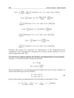
Fig. 2. A limb with its infinitesimal screws
Let
),,(
ZYX
ωωωω
= be the angular velocity of the moving platform, with respect to the
fixed platform, and let
)v,v,(vv
OZOYOXO
=
be the translational velocity of the point O,
see Fig. 2; where both three-dimensional vectors are expressed in the reference frame XYZ.
Then, the velocity state
[
]
OO
vωV = , also known as the twist about a screw, of the
moving platform with respect to the fixed platform, can be written, see Sugimoto (1987),
through the j-th limb as follows
O
5
0i
1i
j
i
j
1ii
V$ω =
∑
=
+
+
{
}
1,2,3j ∈
, (17)
Acceleration Analysis of 3-RPS Parallel Manipulators by Means of Screw Theory
323
where, the joint rate
j
j
32
qω
= is the active joint associated to the prismatic joint in the j-th
limb, while
0=
j
10
ω is the joint rate of the prismatic joint associated to the cylindrical joint.
With these considerations in mind, the inverse and forward velocity analyses of the
mechanism under study are easily solved using the theory of screws.
The inverse velocity analysis consists of finding the joint rate velocities of the parallel
manipulator, given the velocity state of the moving platform with respect to the fixed
platform. Accordingly to expression (17), this analysis is solved by means of the expression
O
-1
jj
VJΩ = . (18)
Therein
•
[
]
6
j
55
j
44
j
33
j
22
j
11
j
0
j
$$$$$$J = is the Jacobian of the j-th limb, and
•
[]
T
j
6
5
j
5
4
j
4
3
j
3
2
j
2
1
j
1
0
j
ωωωωωωΩ = is the matrix of joint velocity rates of the j-
th limb.
On the other hand, the forward velocity analysis consists of finding the velocity state of the
moving platform, with respect to the fixed platform, given the active joint rates
j
q
. In this
analysis the Klein form of the Lie algebra e (3) plays a central role.
Given two elements
[
]
O111
ss$ = and
[]
O222
ss$ = of the Lie algebra e (3), the Klein
form,
{}
*,* , is defined as follows
{
}
O12O2121
ssss,$$ •+•= . (19)
Furthermore, it is said that the screws
1
$ and
2
$ are reciprocal if
{
}
0=
21
,$$ .
Please note that the screw
54
$
i
is reciprocal to all the screws associated to the revolute joints
in the same limb. Thus, applying the Klein form of the screw
54
$
i
to both sides of expression
(17), the reduction of terms leads to
{
}
i
5
i
4
O
q$,V
=
{
}
1,2,3i ∈ . (20)
Following this trend, choosing the screw
65
$
i
as the cancellator screw it follows that
{
}
0=
6
i
5
O
$,V
{
}
1,2,3i ∈
. (21)
Casting in a matrix-vector form expression (20) and (21), the velocity state of the moving
platform is calculated from the expression
QVΔJ
O
T
= , (22)
Parallel Manipulators, New Developments
324
wherein
•
[
]
6
3
56
2
56
1
55
3
45
2
45
1
4
$$$$$$J =
is the Jacobian of the parallel manipulator,
•
⎥
⎦
⎤
⎢
⎣
⎡
×
×
=
333
333
0I
I0
Δ
is an operator of polarity, and
•
[]
T
321
000qqqQ
= .
Finally, once the angular velocity of the moving platform and the translational velocity of
the point O are obtained, respectively, as the primal part and the dual part of the velocity
state
[]
OO
vωV = , the translational velocity of the center of the moving platform,
vector
C
v , is calculated using classical kinematics. Indeed
C/OOC
rωvv ×+= . (23)
Naturally, in order to apply Eq. (22) it is imperative that the Jacobian J be invertible.
Otherwise, the parallel manipulator is at a singular configuration, with regards to Eq. (18).
4. Acceleration analysis
Following the trend of Section 3, in this section the acceleration analysis of the parallel
manipulator is carried out by means of the theory of screws.
Let
),,(
ZYX
ωωωω
= be the angular acceleration of the moving platform, with respect to the
fixed platform, and let
)a,a,(aa
OZOYOXO
=
be the translational acceleration of the point
O; where both three-dimensional vectors are expressed in the reference frame XYZ. Then the
reduced acceleration state
[
]
OOO
vωaωA ×−=
, or accelerator for brevity, of the moving
platform with respect to the fixed platform can be written, for details see Rico & Duffy
(1996), through each one of the limbs as follows
Oj-Lie
5
0i
1i
j
i
j
1ii
A$ω =+
∑
=
+
+
$
{
}
1,2,3j ∈ , (24)
where
jLie
$
−
is the Lie screw of the j-th limb, which is calculated as follows
∑
=
=
⎥
⎥
⎦
⎤
⎢
⎢
⎣
⎡
+
+
+
+
∑
+=
4
0k
1r
j
r
j
1r
r
1k
j
k
j
1k
k
j-Lie
5
kr
$ω$ω
1
$ ,
and the brackets
[
]
** denote the Lie product.
Equation (24) is the basis of the inverse and forward acceleration analyses.
The inverse acceleration analysis, or in other words the computation of the joint acceleration
rates of the parallel manipulator given the accelerator of the moving platform with respect
to the fixed platform, can be calculated, accordingly to expression (24), as follows
Acceleration Analysis of 3-RPS Parallel Manipulators by Means of Screw Theory
325
)$(AJΩ
jLieO
-1
jj −
−=
, (25)
where
[]
T
j
6
5
j
5
4
j
4
3
j
3
2
j
2
1
j
1
0
j
ωωωωωωΩ
= is the matrix of joint acceleration rates.
On the other hand, the forward acceleration analysis, or in other words the computation of
the accelerator of the moving platform with respect to the fixed platform given the active
joint rate accelerations
j
q
of the parallel manipulator; is carried out, applying the Klein form
of the reciprocal screws to Eq. (24), using the expression
QAΔJ
O
T
=
, (26)
where
{
}
{}
{}
{}
{}
{}
⎥
⎥
⎥
⎥
⎥
⎥
⎥
⎥
⎦
⎤
⎢
⎢
⎢
⎢
⎢
⎢
⎢
⎢
⎣
⎡
−
−
−
−
−
−
+
+
+
=
3
,
2
,
,
3
,
2
,
,
Lie
6
3
5
Lie
6
2
5
1Lie
6
1
5
Lie
5
3
4
3
Lie
5
2
4
2
1Lie
5
1
4
1
$$
$$
$$
$$q
$$q
$$q
Q
Once the accelerator
[
]
OOO
vωaωA ×−=
is calculated, the angular acceleration of the
moving platform is obtained as the primal part of
O
A , whereas the translational acceleration
of the point O is calculated upon the dual part of the accelerator. With these vectors, the
translational acceleration of the center of the moving platform, vector
C
a , is computed using
classical kinematics. Indeed
)(
C/OC/OOC
rωωrωaa ××+×+=
. (27)
Finally, it is interesting to mention that Eq. (26) does not require the values of the passive
joint acceleration rates of the parallel manipulator.
5. Case study. Numerical example
In order to exemplify the proposed methodology of kinematic analysis, in this section a
numerical example, using SI units, is solved with the aid of computer codes.
The parameters and generalized coordinates of the example are provided in Table 1.
Parallel Manipulators, New Developments
326
2πt0
/2)]cos[tsin(t0.35sin(t)q
)]in(t)cos(t0.35sin[tsq
(t)cos(t)
2
0.5sinq
aaa
9).963346327 0, 918,( 2682607u
3).713993824- 0, 970,( 7001519u
6).249352503- 0, 85,(.96841278u
9).134130395- 0, 640,( 4816731B
5).350075998- 0, 22,(.35699691B
2).484206394 0, 18,(.12467625B
3
2
1
231312
3
2
1
3
2
1
≤≤
−=
=
−=
===
=
=
=
=
=
=
2/3
Table 1. Parameters and instantaneous length of each limb of the parallel manipulator
According with the data provided in Table 1, at the time t=0 the sixteenth polynomial in
1
Z
results in
0.=
16
1
e11Z.261153294
+
15
1
2e12Z.378734907-
14
1
e13Z.195532604+
13
1
e13Z.373666459-
12
1
12Z.64783709e
-
11
1
e13Z.786657045+
10
1
1Z.3921344e1 +
9
1
e13Z.672039554-
8
1
e13Z.108993550
-
7
1
5e13Z.273968077
6
1
e12Z.964036155+
5
1
e12Z.444113311-
4
1
e12Z.281160758
-
3
1
10Z.82281001e-
2
1
e11Z.246379238+
1
e10Z.627748325+09490873788e
+
The solution of this univariate polynomial equation, in combination with expressions (5)
and (6), yields the 16 solutions of the forward position analysis, which are listed in Table 2.
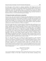
Taking solution 3 of Table 2 as the initial configuration of the parallel manipulator, the most
representative numerical results obtained for the forward velocity and acceleration analyses
are shown in Fig. 3.
Acceleration Analysis of 3-RPS Parallel Manipulators by Means of Screw Theory
327
Solution
1
P
2
P
3
P
1,2
.335)- 0.307, ( 086,± .424)- .994,(.432,± .101)- 1.093,( 364,±
3,4
.471) .899, (.121,
±
.354)- .999, (.361,
±
0)1.099, 13( 468,
±
5,6
.625) .888, (.161, ± .231)- .985,(.236,± .151) .273,(.544,±
7,8
.385)- .054,( 099,
±
.089) .778,( 091,
±
.155) .209,(.558,
±
9,10
.857,.749)(.193,± .314) .312,( 321,± .333,.147)(.528,±
11,12
.869,.709)(.182,
±
.287,.320)( 326,
±
1)1.056, 05( 185,
±
13,14
7).194i, 40( 104,± .615) .950i,( 628,± ).004i,.160(.578,±
15,16
7).195i, 40( 104,
±
4)1.009i,.64( 657,
±
.160) .004i,(.578,
±
Table 2. The sixteen solution of the forward position analysis
Fig. 3. Forward kinematics of the numerical example using screw theory
Furthermore, the numerical results obtained via screw theory are verified with the help of
special software like ADAMS©. A summary of these numerical results is reported in Fig. 4.
Parallel Manipulators, New Developments
328
Fig. 4. Forward kinematics of the numerical example using ADAMS©
Finally, please note how the results obtained via the theory of screws are in excellent
agreement with those obtained using ADAMS©.
6. Conclusions
In this work the kinematics, including the acceleration analysis, of 3-RPS parallel
manipulators has been successfully approached by means of screw theory. Firstly, the
forward position analysis was carried out using recursively the Sylvester dialytic
elimination method, such a procedure yields a 16-th polynomial expression in one
unknown, and therefore all the possible solutions of this initial analysis are systematically
calculated. Afterwards, the velocity and acceleration analyses are addressed using screw
theory. To this end, the velocity and reduced acceleration states of the moving platform,
with respect to the fixed platform are written in screw form through each one of the three
limbs of the manipulator. Simple and compact expressions were derived in this contribution
for solving the forward kinematics of the spatial mechanism by taking advantage of the
concept of reciprocal screws via the Klein form of the Lie algebra e (3). The obtained
expressions are simple, compact and can be easily translated into computer codes. Finally, in
order to exemplify the versatility of the chosen methodology, a case study was included in
this work.
Acceleration Analysis of 3-RPS Parallel Manipulators by Means of Screw Theory
329
7. Acknowledgements
This work has been supported by Dirección General de Educación Superior Tecnológica,
DGEST, of México
8. References
Agrawal, S.K. (1991). Study of an in-parallel mechanism using reciprocal screws. Proceedings
of 8th World Congress on TMM,
405-408.
Alizade, R.I., Tagiyev, N.R. & Duffy, J. (1994). A forward and reverse displacement analysis
of an in-parallel spherical manipulator.
Mechanism and Machine Theory, Vol. 29, No.
1, 125-137.
Carricato, M. & Parenti-Castelli, V. (2003). A family of 3-DOF translational parallel
manipulators.
ASME journal of Mechanical Design, Vol. 125, No. 2, 302-307.
Clavel, R. (1991). Conception d'un robot parallèle rapide à 4 degrés de liberté. Ph.D. Thesis,
EPFL, Lausanne, Switzerland.
Di Gregorio, R. (2002). A new family of spherical parallel manipulators.
Robotica, Vol. 20,
353-358.
Di Gregorio, R. & Parenti-Castelli, V. (2002). Mobility analysis of the 3-UPU parallel
mechanism assembled for a pure translational motion.
ASME Journal of Mechanical
Design,
Vol. 124, No. 2, 259-264.
Fang, Y. & Huang, Z. (1997). Kinematics of a three-degree-of-freedom in-parallel actuated
manipulator mechanism.
Mechanism and Machine Theory, Vol. 32, 789-796.
Gallardo-Alvarado, J., Rico-Martínez, J.M. & Alici, G. (2006). Kinematics and singularity
analyses of 4-dof parallel manipulator using screw theory.
Mechanism and Machine
Theory, Vol. 41, No. 9, 1048-1061.
Gallardo-Alvarado, J., Orozco-Mendoza, H. & Maeda-Sánchez, A. (2007). Acceleration and
singularity analyses of a parallel manipulator with a particular topology.
Meccanica,
Vol. 42, No. 3, 223-238.
Gogu, G. (2005). Mobility of mechanisms: a critical review.
Mechanism and Machine Theory,
Vol. 40, No. 9, 1068-1097.
Gosselin, C.M. & Angeles, J. (1989). The optimum kinematic design of a spherical three-
degree-of-freedom parallel manipulator.
ASME Journal of Mechanical Design, Vol.
111, No. 2, 202-207.
Gough, V.E. & Whitehall, S.G. (1962). Universal tyre test machine, Proceedings of the FISITA
Ninth International Technical Congress, pp. 117-137, May.
Huang Z. & Fang, Y.F. (1996). Kinematic characteristics analysis of 3 DOF in-parallel
actuated pyramid mechanism.
Mechanism and Machine Theory, Vol. 31, No. 8, 1009-
1018.
Huang, Z. & Wang, J. (2000) Instantaneous motion analysis of deficient-rank 3-DOF parallel
manipulator by means of principal screws. In:
Proceedings of A Symposium
Commemorating the Legacy, Works, and Life of Sir Robert Stawell Ball Upon the 100th
Anniversary of a Treatise on the Theory of Screws.
Cambridge.
Huang, Z. & Wang, J. (2001). Identification of principal screws of 3-DOF parallel
manipulators by quadric degeneration.
Mechanism and Machine Theory, Vol. 36, No.
8, 893-911.
Huang, Z., Wang, J. & Fang, Y. (2002) Analysis of instantaneous motions of deficient-rank 3-
RPS parallel manipulators.
Mechanism and Machine Theory, Vol. 37, No. 2, 229-240.
Parallel Manipulators, New Developments
330
Hunt, K.H. (1983). Structural kinematics of in-parallel-actuated robot arms. ASME Journal of
Mechanisms, Transmissions, and Automation in Design,
Vol. 105, 705-712.
Innocenti, C. & Parenti-Castelli, V. (1990). Direct position analysis of the Stewart platform
mechanism.
Mechanism and Machine Theory, Vol. 35, No. 6, 611 621.
Ionescu, T. (2003). Standardization of terminology.
Mechanism and Machine Theory, Vol. 38,
No. 7-10, 597-1111.
Ji, P. & Wu, H. (2003). Kinematics analysis of an offset 3-UPU translational parallel robotic
manipulator.
Robotics and Autonomous Systems, Vol. 42, No. 2, 117-123.
Kim, H.S. & Tsai, L W. (2003). Kinematic synthesis of a spatial 3-RPS parallel manipulator.
ASME Journal of Mechanical Design, Vol. 125, 92-97.
Kong, X. & Gosselin, C.M. (2004a). Type synthesis of 3-DOF translational parallel
manipulators based on screw theory.
ASME Journal of Mechanical Design, Vol. 126,
No. 1, 83-92.
Kong, X. & Gosselin, C.M. (2004b). Type synthesis of 3-DOF spherical parallel manipulators
based on screw theory.
ASME Journal of Mechanical Design, Vol. 126, No. 1, 101-108.
Kong, X W & Gosselin, C.M. (2002). Kinematics and singularity analysis of a novel type of
3-CRR 3-DOF translational parallel manipulator.
International Journal of Robotics
Research,
Vol. 21, No. 9, 791-798.
Lee, K.M. & Shah, D.K. (1987). Kinematic analysis of a three-degree-of-freedom in-parallel
actuated manipulator,
Proceedings IEEE International Conference on Robotics and
Automation,
Vol. 1, 345-350.
Liu, C.H. & Cheng, S. (2004). Direct singular positions of 3RPS parallel manipulators.
ASME
Journal of Mechanical Design,
Vol. 126, 1006-1016.
Liu, X J. & Gao, F., (2000). Optimum design of 3-DOF spherical parallel manipulators with
respect to the conditioning and stiffness indices.
Mechanism and Machine Theory,
Vol. 35, No. 9, 1257-1267.
Lu Y. & Leinonen, T. (2005). Solution and simulation of position-orientation for multi-spatial
3-RPS Parallel mechanisms in series connection.
Multibody System Dynamics, Vol.
14, 47-60.
Parenti-Castelli, V., Di Gregorio, R. & Bubani, F. (2000). Workspace and optimal design of a
pure translation parallel manipulator.
Meccanica, Vol. 35, No. 3, 203-214.
Parenti-Castelli, V. & Innocenti, C. (1992). Forward displacement analysis of parallel
mechanisms: Closed form solution of PRR-3S and PPR-3S structures.
ASME Journal
of Mechanical Design,
Vol. 114, No. 1, 68-73.
Rico, J.M. & Duffy, J. (1996). An application of screw algebra to the acceleration analysis of
serial chains.
Mechanism and Machine Theory, Vol. 31, 445-457.
Rico, J.M., Gallardo, J. & Duffy J. (1999). Screw theory and higher order kinematic analysis of
open serial and closed chains.
Mechanism and Machine Theory, Vol. 34, No. 4, 559-
586.
Romdhane, L., Affi, Z. & Fayet, M. (2002). Design and singularity analysis of a 3-
translational-dof in-parallel manipulator.
ASME Journal of Mechanical Design, Vol.
124, No. 3, 419-426.
Stewart, D. (1965). A platform with six degrees of freedom.
Journal Proceedings IMECHE Part
I,
Vol. 180, No. 15, 371-386.
Sugimoto, K. (1987). Kinematic and dynamic analysis of parallel manipulators by means of
motor algebra.
ASME Journal of Mechanisms, Transmissions, and Automation in
Design,
Vol. 109, 3-7.
Tsai, L W. (1999)
Robot analysis. John Wiley & Sons.
17
Multiscale Manipulations with Multiple Parallel
Mechanism Manipulators
Gilgueng Hwang and Hideki Hashimoto
The University of Tokyo
Japan
1. Introduction
While recent years have brought an explosive growth in new microelectromechanical
system (MEMS) devices ranging from accelerometers, oscillators, micro optical components,
to micro-fluidic and biomedical devices, our concern is now moving towards complex
microsystems that combine sensors, actuators, computation and communication in a single
micro device. It is widely expected that these devices will lead to dramatic developments
and a huge market, analogous to microelectronics.
However, several problems (e.g., sticking effect) exist which are preventing fully
autonomous manipulation with dextrous skills at the micro-scale. Dextrous manipulation,
requiring precise control of forces and motions, cannot be accomplished with a conventional
robotic gripper; any slave should be more anthropomorphic in design. These kinds of
dextrous manipulations still need human operator assistance.
Task-based autonomous manipulation has been explored by many researchers to overcome
micromanipulation problems. Fearing et al. developed an automated microassembly system
with ortho-tweezers and force sensing (Fearing et al., 2001). However, the workspace was
really small and the range of the target object was pretty much limited.
Inspection, prototyping or repairing of a miniaturized system which require human’s
flexible intelligence relies on the human’s operation under a microscope. These tasks are
very stressful and cannot be done by an autonomous system such as Fearing’s prototyping
machine. As a human-centred manipulation, teleoperation has been researched for the
ability to display the expanded micro environment to the human operator. By combining
with haptic interfaces which provide force feedback, a human operator could operate a
micro scale object with enough telepresence and reality, increasing the human’s operability
and operational efficiency. There are many applications based on bilateral teleoperation
control (Kosuge et al., 1995; Hannaford & Anderson, 1988). A chopstick-like
micromanipulation system having a two-fingered micro-hand as a slave was developed
(Tanikawa & Arai, 1999). However, this system did not support force feedback to the
operator, which does not provide enough telepresence. A surgical system such as the da
Vinci System (Dosis et al., 2003) is a good application since humans and robots collaborate
with each other for the purpose of high performance with safety. In our previous work, a
tele-micromanipulation system was proposed to enable micro tasks without stress (Ando et
Parallel Manipulators, New Developments
332
al., 2001). The above teleoperated systems had enough functionality in a specified
application target instead of losing dexterity during operation.
Fig. 1. Concept of micromanipulation system using multiple parallel mechanism
micromanipulators
There are still many applications which require human intelligence to overcome the
limitation of artificial intelligence (AI) technology and the limited dexterity of the slave
manipulator. For these reasons, humans should intervene in the manipulation process.
Dexterous manipulation, requiring precise control of forces and motions, cannot be
accomplished with a conventional robotic gripper; a slave should be more anthropomorphic
in design. These kinds of dextrous manipulations still need a human operator’s assistance.
In the mean while, the single-master multi-slave (SMMS) system was developed using the
virtual internal model (Kosuge et al., 1990). It enables better dexterous teleoperation system
without increasing the human’s operational d.o.f. However, their work relied on the
reference position distribution without considering the force feedback which made the
comparative analysis with other systems. The communication delay issue of SMMS
teleoperation by decomposing the dynamics of multiple slaves has been studied showing
several simulated results (Lee & Spong, 2005). However, it was not implemented to the real
time system for the practical systems different dynamics than the theory.
These concepts of multiple robot configurations from macro scale can be the break through
of conventional micro/nanomanipulation.In our research, we implement dexterous
micromanipulation system based on the SMMS concept (Hwang et al., 2007). A single
PHANToM haptic device as a master device and dual 6-d.o.f. parallel micromanipulators as
slave devices are adopted as shown in Fig. 1.
Using dual-slave manipulators is expected to enhance the performance or dexterity of the
total system compared to our previous work, which had a single slave manipulator (Ando et
al., 2001).
This chapter continues with the system structure of tele-micromanipulation systems and the
parallel manipulator as a slave device is briefly introduced. The singular position and
manipulability analyses are done in the Section 3. Section 4 covers the overall strategy and
the mapping method between the PHANToM master device and the dual slave
manipulators. Finally, several experimental results (e.g., accuracy evaluation, master–slave
position/force-mapping method) are shown. Notation is based on the reference (Paul, 1981).
Multiscale Manipulations with Multiple Parallel Mechanism Manipulators
333
Fig. 2. Electronics and control box for dual parallel mechanism micromanipulators
connected to the pc
2. SMMS system overview
In this section, a tele-micromanipulation system is introduced. Figure 2 shows the
configuration of our tele-micromanipulation system. A parallel manipulator having an
Fig. 3. Parallel mechanism micromanipulator
Parallel Manipulators, New Developments
334
original mechanism is used as a slave manipulator in the teleoperation system. The slave
manipulator and master system are connected using an Ethernet and they are used to
perform teleoperations through the network. A bilateral control system was adopted to
realize the overall teleoperation system.
2.1 SMMS architecture
The proposed SMMS tele-micromanipulation system is an extension of our previous system
(Ando et al., 2001) that supported 1:1 master–slave tele-micromanipulation.
We proposed a prototype of the SMMS tele-micromanipulation system which applies dual-
parallel micromanipulators in a ‘V’ configuration which is similar to the natural human
hand position while assembling or manipulating an object.
Figure 1 show the overall system configuration including the master haptic device, slave
manipulators and the visual interface connected on RT-Middleware (Ando et al., 2005). RT-
Middleware technology has several advantages for constructing SMMS system architecture
such as providing a flexible network connection environment which is required for multi-
modal displaying or human–robot shared control. The shared controller plays a major role
in generating the multi-slave’s reference position and internal force by human–robot
cooperation. However, in this paper, we do not go further with the shared control. Each
slave controller drives six link shafts to position the parallel mechanism end-effector within
about 10 μm positioning accuracy. There are three RT components with a position/force IO
interface through the network. Both slave manipulators are controlled by a PC (Pentium III
500 MHz × 2). A real-time extension for Linux (ART-Linux) is used as the operating system
to perform motion control at 1-kHz sampling rate.
The slave manipulator with a parallel link mechanism as shown in Fig. 3 is used as a slave
manipulator. Compared to the serial mechanisms used in normal robot arms, the parallel
mechanism has merits such as high stiffness, high speed and high precision.
A serial link mechanism PHANToM haptic device is adopted as our master device. This
device allows the 6-d.o.f. measurement including 3 d.o.f. of each translational and rotational
motion. Also, the 3-d.o.f. translational force feedback is supported by this master device.
Real Time Linux was used as the operating system to control the master with 1-kHz
sampling frequency.
3. Kinematics analysis of slave device
It has already been mentioned in Section 2 that there exist several characteristics of a novel
parallel mechanism slave micromanipulator being used in this research. However, in the
cooperative manipulation of a multi-slave system, several problems of parallel manipulators
such as a singular position possibly become more serious than in independent
manipulation. Therefore, singular position and the manipulability of the parallel
manipulator used in this research are discussed in this section.
The most feasible arrangement of both manipulators considering the result of
manipulability is also described in the latter part in this section.
3.1 Inverse kinematics of parallel micromanipulator
It is already mentioned in chapter.3 that there exist several characteristics of a novel parallel
mechanism slave micromanipulator being used in this research. However, in the
Multiscale Manipulations with Multiple Parallel Mechanism Manipulators
335
cooperative manipulation of multi-slave system, several problems of parallel manipulators
such as singular position possibly become more serious than in the independent
manipulation. Therefore, analyses on the kinematics, singular position, and manipulability
of the parallel manipulator which is used in this research should be given in this section.
The most feasible arrangement of both manipulators is also described in the latter part in
this section. An inverse kinematics analysis on the parallel mechanism micromanipulator is
described in this section. Figure 4 shows coordinate system adopted for kinematics analysis.
Point O is the origin and the criteria coordinate is the base coordinate system.
(a)
(b)
Fig. 4. Coordinate system of parallel mechanism manipulator (a), and position tracking (b)
We define each variables and constants in the following manner.
(
ϕ
θ
φ
,, ) : posture of end-effector,
R
: Rotation matrix which represents the posture of the end-effector,
i : Chain number,
b
a : Vector from centre of base to base joints,
b
r : Length of
b
a ,
t
d : Vector from centre of end-plate to end-table joints,
t
r : Length of
t
d ,
z : Unit vector from base joint datum point to actuator joints datum point,
i
l : Length of chain of prismatic joints,
s : Unit vector from actuator joints datum point to end-plate joints datum point,
From relations between base joints and end-effector joints, we get
Parallel Manipulators, New Developments
336
+
−=+,
ti bi i
p
Rd a l z bs (1)
Where
i
L is used for
+
− .
ti bi
p
Rd a
−
=
ii
Llzbs. (2)
Both sides of equation are squared and because
=
=
22
1, 1,zs and we get the following
equation.
−
⋅+−=
222
2( ) 0.
iiii
lLzlLb (3)
This equation is solved for
i
l , and we get,
=⋅± −+⋅
22 2
() ().
ii ii
lLz bLLz (4)
Where,
==( , , ), (0,0,1)
ixyz
LLLLz and using the constraints that the chains sign of square
root is negative, we get the following equation.
=− −−
22 2
.
izi xiyi
lL bL L
(5)
Thus, the length of the link
i
l is determined by the tip position of the end-effector
ϕ
θφ
(,,, ,,)Fxyz . In other words, we can compute the reference link length
61−
l from the
position and posture of end-effector.
A simulation was conducted to verify the validity of the calculated inverse kinematics for
our purpose. As y-directional reference sinusoidal input for simulation is set as following.
π
=
20sin 2Yt (6)
The resolution of encoder attached to each linear driving link is given as the 0.122μm. Figure
4b shows the result of the simulation. It is quite well being tracked to the given sinusoidal
trajectory with the maximum tracking error 0.150μm. This result proves the validity of the
inverse kinematics calculation conducted here, also almost of the error is generated from the
quantization process with the encoder resolution.
3.1 Singular position analysis
There exists a singular position in the manipulator workspace. The d.o.f., decreases around
this position or point. Therefore, it should be avoided in the control of the manipulator.
Here, we need to analyze this singular position of our system by some calculations.
First of all, the Jacobian matrix can be mathematically defined as follows. Assuming that an
n -d.o.f. manipulator is working in an m -dimensional task space, where m < n , we have:
=
()
v
vJxi (7)
Multiscale Manipulations with Multiple Parallel Mechanism Manipulators
337
Where
v and
i
indicate the Cartesian and joint velocity vectors defined in the task space
n
R
and the joint space
m
R
, respectively, and
v
J represents a nm
×
Jacobian matrix.
v
J
is also considered as a Jacobian matrix which contains
φ
as an Euler angle.
In the case that we put the column vector of
v
J as
j
M
(
j
= 1 ~ 6), the relation between
v and i can be described as:
=
=
∑
6
1
jj
j
viM
, (8)
Therefore, the singular position can be obtained by the calculation of the determinant of the
Jacobian matrix
v
J
:
=
det 0
v
J (9)
The singular position may cause some problems which can be measured by the
manipulability. Therefore, we need to visualize the manipulability of dual manipulators on
the overall workspace.
Fig. 5. Kinematical model of the cooperative system. The universe, and left and right
manipulator’s coordinate frames are described as {A}, {B}, {C}, respectively.
3.2 Multi-micromanipulator analysis
In the case of the dual-micromanipulator system, a proper coordinate system for each
manipulator needs to be analyzed. Figure 5 shows the proposed model of the cooperative
system.
There are several advantages of this design which can be summarized as high flexibility to
random target objects, high dexterity, etc.
The angle between two manipulators is 90◦ and the initial points of the end-effector are set
as (5, 0, 5) mm and (−5, 0, 5) mm. Frame B is described by:
=
⋅−(,45) (5,0,5),
A
B
CRoty Trans
(10)
Parallel Manipulators, New Developments
338
=
−⋅ − −(,45) (5,0,5).
A
C
CRoty Trans (11)
Equations (10) and (11) show the conversion matrix for arranging the coordinate system of
each manipulator.
3.3 Manipulability measure
The manipulability measure
w is proposed to measure quantitatively the ability to change
the position and orientation of the end-effector from the view point of the kinematics
(Yoshikawa, 1985). There is also a trade-off between accuracy and manipulability. As the
proposed parallel manipulator has no redundant d.o.f., w is represented as follows:
= det( ) .
v
wJ (12)
The kinematical manipulability in the dual-micromanipulator’s workspace which is parallel
to the xy plane can be referred from the reference (Hwang et al., 2007). The human operator
is possibly able to avoid the singular position which is located around the position with zero
manipulability. It is easily verified that mapping the centre position of both manipulators
with the haptic reference position gives consistency of manipulability, because
manipulability is plotted as symmetrical to the plane x = 0.
4. Manipulation strategy
4.1 Master/slave mapping
Figure 5 depicts the kinematical model of the proposed system including mapping method.
The reference position of the haptic device is mapped into the centric of both end-effectors’
tip positions. At the same time, the internal force generated by both end-effectors conflicts
with the target object is fed into the user through the haptic device. In this section, a novel
mapping method between the SMMS system arranged as shown in sections 2 and 3 and
finally a valid manipulation strategy are discussed. Basically, the reference position of the
haptic device should be scaled into the center of both manipulators’ tip positions during the
free motion. The reference position to each slave manipulator is calculated from the current
position and posture of the haptic device. It enables to assure more workspace for both of
manipulators. Also, the same manipulability of both manipulators can be obtained on z axis
(xy=0), because the manipulability of both manipulators is symmetrically plotted to the
plane x = 0. It can be the most feasible interface to the human operator with only two-
dimensional visual information. Several experimental results to verify the proposed
mapping method will further be shown in section 5.
4.2 Virtual mapping method
This section introduces a novel mapping method between SMMS devices arranged as
shown in the section 2 and 3 (see Figure 1) and an improved manipulation strategy is
proposed in order to emphasize the human manipulation in the micro world.
Since the master device and the slave devices have very different kinematical structures in
this system, the usual direct mapping method (e.g., joint-to-joint mapping) cannot be useful
in our system. A virtual mapping method was used to connect between the human’s hand
and the non-anthrophormous slave device, where their feedback strategy was based on the
fingertip-level force feedback (Griffin et al., 2003). Our system has the serial link master
device but the parallel link slave devices that define a new manipulation approach. This
Multiscale Manipulations with Multiple Parallel Mechanism Manipulators
339
paper introduces a novel approach to realize more dexterous control with the simplified
master device to control multiple slave devices, discussed in relation to the object based roll
and yaw angle control to adjust the grasp force control. Figure 5 and 6 show this new
manipulation approach.
The roll and yaw angle of the phantom haptic interface is measured and used to provide the
roll and yaw orientation of the manipulated object. Then the reference grasping force is
proportional to the measured pitch angle of PHANToM haptic interface. This reference
object size is mapped into the width of both the slave’s tip positions.
As shown in Fig. 5, the virtual mapping parameters are described in the virtual robot
coordinate which is denoted as V . Given the reference centre position of the virtual object
m
q , we need to calculate the reference tip position of each end-effector, .,
ji
qq The centre
position of the virtual object is described as
m
V
q .
mi
V
q and
mj
V
q
describe the vector from
the virtual object centre to each of slave tip position. This term can be obtained from the roll
and yaw angles (
yr
θ
θ
, ) commanded from the master haptic device. The reference grasping
force
r
g
F is generated by the pitch angle (
p
θ
). Then,
mi
V
q and
mj
V
q can be calculated by
the following rotational matrix:
θθ θ θθ
θθ θ θθ
θθ
⎡⎤
−
−
⎡
⎤
⎢⎥
⎢
⎥
=
⎢⎥
⎢
⎥
⎢⎥
−
⎢
⎥
⎣
⎦
⎣⎦
cos cos sin cos sin
/2
sin cos cos sin sin 0
0
sin 0 cos
ry r ry
V
mi r y r r y
yy
d
q
. (7)
where d is the distance between two virtual tip positions which is calculated to assign
virtual dynamics (spring constant:
v
s ) to the virtual object as follows:
=
1
,
r
gv
Fs
d
θ
=Δ = − .
VV
p
i
j
dqq (8)
Then, each slave’s tip position based on the virtual object is:
=+,
VV V
immi
qq q =+.
VVV
jmmj
qqq
(9)
4.3 Force feedback strategy
Here the question “what kind of haptic feedback is efficient?” arises. To answer this
question, we need to consider the several factors including the contact type between the
end-effector tip and the object. A haptic feedback contributes to increase the operability of
human resulting in the improved overall performance of manipulation. Considering that
our concern is to develop the single-master multi-slave telemicromanipulation framework,
the conventional master, slave direct force feedback is not feasible. As shown in the
Figure.4.8, in the case of 1:1 master slave system, a direct feedback from the force sensor is
an effective for recognizing the slave side by human. If an 1:N master slave system as the
grasping an object by human’s hand with five fingertips, still human recognizes the
grasping condition from multiple fingertip sensing. To assure the stable grasping in 1:N
Parallel Manipulators, New Developments
340
system, each end-effector of N slave devices should cooperate with each other to regulate
the grasping force by transferring the grasping force to the human operator through the
haptic interface. This strategy helps to regulate the grasping force by both the human’s
control and robot’s control. Looking it in coordinate system, the exerted force by the object
to the slave and the feedback forces in case of 1:1 feedback strategy are denoted as
i
R
f and
i
U
f respectively. These are scaled between the master and the slave to amplify the force in
the micro environment. However, in the case of 1:N feedback strategy, it is assumed that the
virtual thread exerting the feedback force (
U
i
f
) to the human operator by the slave’s
applied forces (
i
R
f ) to the object.
Then, the force diagram between the multi-slaves and the object should be analyzed to
calculate the proper feedback to the user.
μ denotes the friction coefficient between the object and the slave.
i
f is the internal force
term at the
th
i slave’s contact position.
i
f
μ
describes the frictional force upward caused by
the internal force (
i
f at a
th
i contact position.
r
θ
denotes the commanded roll angle of the
manipulated object which forms the orthogonal downward force (
ri
f
θ
μ
cos ). If N slaves
are handling an object, the resisting force (
F ) downward is,
μ
θ
=
cos
ir
FNf (10)
Assuming that the scaling factor between the master and the slave for micromanipulation
tasks is given as,
=
(,,)
pppp
A
diagAAA (11)
Then the feedback force to the human operator which is defined here as the
i
U
f is obtained
from,
=
U
ip
f
AF (12)
A question is now arising mainly about how to obtain
i
f in real time and deliver it to user.
The simple calculation to obtain
i
f is implemented to the SMMS system in section 4.4.
4.4 Internal force decomposition
When multiple manipulators grasp an object, the force applied by multiple robots can be
decomposed into motion-inducing force and internal force. Especially, the internal force
should be kept in a certain range to assure the stable grasping and safety of object. In the
proposed cooperative master–slave manipulation system, the internal force to squeeze the
grasped object is fed into the human operator through the master haptic device. Figure 5
depicts two manipulators cooperating to grasp a single object.
Multiscale Manipulations with Multiple Parallel Mechanism Manipulators
341
Force decomposition using the theory of metric spaces and generalized inverses was
attempted (Bonitz & Hsia, 1994). It is assumed that each manipulator grasps the object
rigidly, exerting both forces and moments on the object. The net force at the object frame is
related to the forces applied by the manipulators by:
=
T
obj o
f
J
f
(13)
where
⎡⎤
=
⎣⎦
T
TT
obj o o
ffm is the net force and moment at the object frame,
⎡⎤
=
⎣⎦
12
TTT
ooo
J
JJ.
oi
J
is the Jacobian from the object frame to the
th
i
end-effector
frame,
⎡⎤
=
⎣⎦
1122
T
TTTT
ffmfm.
i
f is the force and
i
m is the moment applied by the
th
i
end-effector.
⎡
⎤
=
⎣
⎦
T
iixiyiz
pppp is the vector from the
th
i
end-effector to the object frame:
⎡
⎤
=
⎢
⎥
−
⎣
⎦
33
3
T
T
oi
i
IO
J
PI
(14)
−
⎡
⎤
⎢
⎥
=−
⎢
⎥
−
⎢
⎥
⎣
⎦
0
0
0
iz iy
iiz ix
iy ix
pp
Pp p
pp
(15)
The applied force
f is decomposed into motion-inducing,
M
f
, and internal,
I
f
, with:
Φ
=−(1 ) ,
TT
Ioo
f
JJf (16)
Where,
T
o
T
o
JJ
Φ
is a generalized inverse of
T
o
J . The projections
T
o
T
oM
JJP
Φ
= and
T
o
T
oI
JJIP
Φ
−=
project the applied force onto the motion inducing force subspace, ,
M
F
and the internal force inducing force subspace,
,
I
F respectively. If
),()(
T
oo
T
o
JrankMJJrank = the weighting matrix
M
can be used to compute a
generalized inverse of
.
T
o
J
Therefore:
Φ−
⎡
⎤
⎢
⎥
⎢
⎥
==
⎢
⎥
⎢
⎥
⎣
⎦
33
1
13
33
23
1
() .
2
TT
oooo
IO
PI
JMJJMJ
IO
PI
(17)
Using (13) and (14), the decomposition of f is:
Parallel Manipulators, New Developments
342
−
⎡
⎤
⎢
⎥
+− −
=
⎢
⎥
−−
⎢
⎥
⎢
⎥
−−+
⎣
⎦
12
12122
12
121 1 2
()
()
()
I
ff
mPPfm
f
ff
PPf mm
. (18)
Fig. 6. Virtual mapping experiment:
,
R
ij
q
are robot’s Cartesian references,
,
R
ij
l are robot’s
link coordinates,
,
R
qi
l
and
,
R
qj
l
are quantized robot link configuration and
,
R
qi
q
and
,
R
qj
q
are
resultant robot control configuration.
4.5 Manipulation strategy
In much previous master–slave manipulation research, the whole task was done by only the
human operator.
However, in the case of the SMMS system, there exist d.o.f. differences between the master
and the slave. Therefore, it is a good idea to build a whole manipulation process with
several task phases.
In this paper, a human machine cooperative manipulation strategy is proposed as shown in
Fig. 6. User is assumed to monitor the target object under the two-dimensional (2-D) visual
information on the task space.
As a first phase, both slave manipulators approach to the target object following the
reference position scaled from the haptic device operated by the human. Once one of both
end-effectors is contacted with object, the grasping phase is started. An autonomous
grasping algorithm leads to a stable grasp. Then, the user makes a movement of the target
object grasped between both end-effectors. To release the object, operator needs to lead the
object to be touched on the ground. The problem caused by the d.o.f. difference between the
master and the slave is overcome through the proposed manipulation strategy.
Multiscale Manipulations with Multiple Parallel Mechanism Manipulators
343
(a) (b)
(c) (d)
Fig. 7. Dual-micromanipulator’s manipulability (w). Upper and lower panels show the left
and right manipulators, respectively.
5. Experiments
5.1 Positioning accuracy experiment
First of all, a rectilinear movement experiment was performed to evaluate the system’s
overall positioning accuracy, which is a trade-off with manipulability. Figure 6 shows the
parallel line drawing. Intervals between lines of 10 μm were used. Observed intervals of
parallel lines are about 11 μm. In this case intervals are not the same as the reference
intervals; however, almost regular intervals were observed. Movement error is caused by an
encoder resolution which was set as 0.122 μm.
5.2 Trajectory tracking experiment
Figure 6 describes the controller of an overall system to show the mapping. An experiment
on micro-positional synchronization using our micromanipulation system was conducted.
Parallel Manipulators, New Developments
344
The user operates the PHANToM device with a 3-D random or circular trajectory. This
PHANToM reference trajectory generated by the human operator contains the scale factor
between the master and the slave. The trajectory of the PHANToM reference and the
resulting trajectory of both end-effectors centre position is shown in Fig. 7a,b. We generated
two different trajectories which are circular and random motions with a single master
device. The following trajectory of both slave end-effectors centre position is depicted as a
solid line. The validity of our proposed positional mapping method in real-time operation is
verified with this result. Through the result shown in Fig. 7a,b, both slave end-effectors are
kept at a certain width during the experiment. The reference trajectory of the single master
device is controlling two slave devices without coupling them to smaller scale applications
such as micro- and nanomanipulations, which require higher positioning accuracy. These
results strengthen the feasibility of the single-master controlled multi-slave system.
Other experiments were conducted to verify the proposed object mapping method. A
human operator is handling a 1 cm
3
cubic object with the PHANToM haptic interface. In Fig.
5, the vector from the left to right contact position is defined as:
=−
12 2 1
,
RRR
qqq (17)
Where
R
i
q depicts the
th
i contact position in the robot coordinate system. The yaw angle of
the virtual object is controlled by a sinusoidal wave or the human operator’s arbitrary
operation. First, the sinusoidal yaw angle input is given to prove the proposed mapping
method. Figure 7c,d show the 3-D trajectory of both end-effectors’ tip positions and the
width between them. The reference position of the virtual centre is constrained to be static.
It is verified that the width is kept static during the operation. The reference roll, pitch and
yaw angles are converted between the user’s frame and the robot’s frame as follows:
θθ
=+
,,
1
1.0,
36
RU
y ref y ref
(18)
θθ
=
,,
0.05 ,
RU
p
ref p ref
(19)
θθ
=
,,
0.1 ,
RU
r ref r ref
(20)
These reference inputs are decided empirically by considering both the workspace and
object scale. The experimental results are shown here. In Fig. 7d, the object’s orientation is
shown following the yaw operation by the human operator. Anglex , Angley and Anglez are
angles between
12
R
q
and each axis. These results show that the developed SMMS system
can realize low-cost, object based 6 d.o.f., and even compact-sized moment control by both
slaves’ translational movement. It is promising to the development of dexterous
micro/nanomanipulation system with ultra-high precision positioning accuracy.
5.3 Force mapping experiment
Several experiments were further performed to verify how feasible it is for us to adopt the
decomposed internal force derived in section 4. Another purpose of this experiment is to
obtain the desired internal force for stable grasping during several primitive tasks. A square
Multiscale Manipulations with Multiple Parallel Mechanism Manipulators
345
stylen block 10 mm in width, length and height was used in this experiment. Figure 16
shows the internal force plotted for several grasping phases such as keeping the grasped
object, parallel movement and 10 times iterative grasping/releasing. Transferring force to
the user gives the teleoperation more transparency which is closely correlated to the user
operability and the task performance. In the case of used stylen bock experiment, it is found
that a reasonable choice of the internal force during the grasp phase should be made around
5 mN in each direction. Also, the Figure 6 describes the controller of a phase transition
should be done by the event which is the change of internal force around the transition
phase. Especially, in the iterative grasping/releasing phase, it is possibly able to be used for
compensating the deficiency of the master’s d.o.f.
Fig. 8. Styren block pick-and-place experiment: schematic (a) pick up 10 mm (b) move 10
mm (c) release onto substrate. Operation: (d) grasp (e) pick up (f) move (g) release.
5.4 Pick-and-place of styrene block
We conducted several experiments using a 10 mm cubic styrene block, roe (4-6 mm) to
demonstrate the feasibility of our proposed system for deformable objects in different scale
and mechanical properties.
First, pick-and-place of a stylen cubic block (1 cm
3
) was performed to show validity of the
proposed dexterous manipulation strategy. Figure 8 shows the demo experiment. The
distance between the initial and the target point is 1 cm. The human operator recognizes the
target object from the visual display of the microscope and operates the single haptic
interface to the contact position of the object. Then, the pitch angle of the haptic interface is
controlled by the user to give enough grasp force with the internal grasp force display.