Parallel Manipulators Towards New Applications Part 3 pdf
Bạn đang xem bản rút gọn của tài liệu. Xem và tải ngay bản đầy đủ của tài liệu tại đây (1.28 MB, 30 trang )
Quantifying and Optimizing Failure Tolerance of a Class of Parallel Manipulators
53
Table 1 also provides another important inference which is significant from the design
perspective. Any redundant manipulator gives very low optimal fault tolerant
manipulability values for more than one failures, and these values decrease drastically with
number of failures. For example, for two failures in an octopod the optimal fault tolerant
manipulability is 0.189 and, for two and three failures in a nanopod the optimal fault
tolerant manipulabilities are 0.288 and 0.109 respectively. This means that under the
hypothesis of equal probability of failure for each actuator, it is not practical to design
manipulators optimally fault tolerant to more than one fault.
4. Symmetric orthogonal Gough Stewart platforms
4.1 Gough Stewart platforms
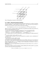
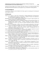
A Gough-Stewart Platform (GSP) is a parallel manipulator consisting of a base, a moving
platform (or payload) and struts. The length of struts is controlled by actuators. The struts
have spherical joints at the payload end and U joints at the base. To provide six degrees of
freedom, six struts are commonly used. Figure 1 is a diagrammatic representation of a GSP.
Payload attachment points and base attachment points are represented by
i
p and
i
q
(
,6}{1,2,3,4,5#i ) respectively.
Fig. 1. Gough-Stewart Platform
OGSPs are a special class of GSPs that provide kinematic and dynamic decoupled control.
Therefore, OGSPs are being widely used in commercial, military and space applications.
Scientists at Northrop Grumman Space Technologies (NGST) are currently experimenting
with an 8-strut OGSP. More recent applications of OGSPs include laser tracking and
pointing, ultra-precise manipulation (McInroy & Jafari, 2006) and robotic surgery (Wapler et
al., 2003). The very nature of these applications makes maintenance or repair of
manipulators very difficult. Moreover, a single failure may compromise the fulfilment of
objective or cause costly downtime. As a consequence, it is desirable to design OGSPs which
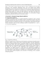
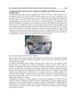
can sustain failures, while retaining an acceptable level of manipulability. Figure 2 shows
one of the flexure jointed hexapods at the University of Wyoming. It has a mutually
orthogonal geometry.
Parallel Manipulators, Towards New Applications
54
Fig. 2. A Flexure Jointed Hexapod at the University of Wyoming
Recent research has shown that symmetric groups of struts can be used to generate OGSPs
having desired properties at their home position (McInroy & Jafari, 2006) and several new
results have been obtained.
The following part of this section recapitulates important results from (McInroy & Jafari,
2006).
4.2 Kinematics of symmetric OGSPs
The inverse Jacobian,
M
, of a GSP maps the generalized velocity of the payload to the
corresponding joint velocities of each strut ( MV=
!
!
"
). It has the form:
1 1
=
T T
T T
l l
u v
M
u v
(
)
*
+
*
+
*
+
,
-
"
"
% %
"
"
(18)
where
3
, R#
ii
vu
"
"
,
iii
upv
"
"
"
$= .
i
u
"
is the unit vector along strut i and
3
R#
i
p
"
is the moving
platform attachment point of strut i . Please refer to Figure 1. Note that, even though
M
is
called the inverse Jacobian to comply with the robotics standard, its computation does not
require inversion, thus it is well defined for all GSP.
-#+./.0.$/6, Let )(
6
R
$
#
l
MM . Write
=
T T
M
U V
(
)
,
-
Quantifying and Optimizing Failure Tolerance of a Class of Parallel Manipulators
55
where
U , )(
3
R
l
MV
$
# . We say
#
M
GSP,
M
is a Gough-Stewart Platform, if:
/ 1][11=)( #UUdiag
T
/ 0=)( VUdiag
T
We say
M
is a Weighted Orthogonal Gough-Stewart Platform,
#
M
w-OGSP, if
#
M
GSP
and:
/ KM
M
T
is a diagonal matrix for a diagonal
K
.
Where
I
K
= these matrices become the Orthogonal Gough-Stewart Platforms.
Fig. 3. [4 4] cylindrical OGSP with optimal fault tolerant manipulability
(McInroy & Jafari, 2006) develops properties and designs of symmetrical weighted OGSPs.
Struts that are geometrically symmetrical are treated together, so the entire OGSP is
decomposed into m different groups, with the
th
i group having
i
n struts. Then
0 1
1 2
=
T
m
n n n n
"
is a vector of positive integers describing the number of struts in each group. The total
number of struts in the GSP is then
j
m
j
nl
'
1=
= . Let
3
, R
#
ijij
vu
"
"
correspond to the
th
i strut in
group
j
. Let ][=
121
1
2111 m
m
nn
uuuuuU
"
#
"
"
#
"
"
and ][=
121
1
2111 m
m
nn
vvvvvV
"
#
"
"
#
"
"
. A GSP can then be found
for these struts by letting
][=
TT
VUM .
Parallel Manipulators, Towards New Applications
56
Following is the summary of results in (McInroy & Jafari, 2006).
*%$7$6.0.$/'8) Conditions (a) and (b) in the GSP definition are satisfied if
= , =
ij ij
ij ij ij x ij y
ij ij ij ij
ij
S C
u S S v x v y v
C
2 3
2 3
2
( )
* +
* +
.
* +
* +
, -
"
" " "
(19)
where
xS
x
sin= , xC
x
cos= , R
#
ijijijij
yx ,,,
3
4
, and
= , = .
0
ij ij ij
x y
ij ij ij ij ij
ij
S C C
v C v C S
S
3 2 3
3 2 3
2
(
)
( )
*
+
* +
*
+
&
* +
*
+
* +
*
+
&
* +
, -
,
-
" "
(20)
Conversely, if
#
M
GSP, then
M
may be represented by a parameterization given by (19)
and (20).
!"#$%#&'9) Let all groups contain more than two struts, i.e.
2>
min
j
j
n . Then #
M
w-OGSP
if
/ The same angle,
j
4
, is used for all struts in group
j
, i.e.
jij
4
4
= ,
/ The same x component of v
"
,
j
x , is used for all struts in group
j
, i.e.
jij
xx = ,
/ The same y component of v
"
,
j
y , is used for all struts in group
j
, i.e.
jij
yy = ,
/ The same k ,
j
k
, is used for all struts in group
j
, i.e.
jij
kk =
,
/ Struts in a group are rotated about the z-axis equal amounts, i.e.
j
jij
n
i 1)(2
=
&
.
5
33
,
/ 0=xA
x
"
and 0=yA
y
"
,
where
1 1 1
2 2 2
= , = , = ,
m m m
x y
x y
x y
x y
2
2
2
2
(
) ( ) ( )
*
+ * + * +
*
+ * + * +
*
+ * + * +
*
+ * + * +
,
- , - , -
"
" "
% % %
1 1
2 2
= , = ,
m m
k
k
k
k
3
3
3
3
(
) ( )
*
+ * +
*
+ * +
*
+ * +
*
+ * +
,
- , -
"
"
% %
1 1 2 2
1 2
= [ ],
x m m
m
A k n S k n S k n S
2 2 2
#
(21)
1 1 2 2 2 2 2
1 2
= [ ].
y m m
m
A k n S k n S k n S
2 2 2
#
(22)
Quantifying and Optimizing Failure Tolerance of a Class of Parallel Manipulators
57
R#
jji
k,,
3
4
may be freely chosen. x
"
and
m
y R
#
"
may be freely chosen to satisfy (F).
Furthermore, if
2
i
6
denotes the
th
i diagonal element of KM
M
T
, then
2 2
1 2
=1
2
1
= = ,
2
2
6 6
'
!
" "
#
"
"
$ % & (23)
2 2
3 1
=1
= 2 ,
6
6
&
'
!
" "
"
$ % (24)
2 2 2 2
4 5
=1
2
1
= = ( ),
2
!
" " " "
#"
"
$ % ' ( )
2
6 6
.
'
(25)
2 2
6
=1
2
= .
2
6
'
!
" " "
#"
"
$ % ( & (26)
In (Aphale, 2006) robust fault tolerance is defined as the property by which the rank of M
equals 6 or the number of struts remaining after failures, whichever is minimum. Not all
geometric designs of OGSPs are robustly fault tolerant. In fact, it has been proved that [3 3 2]
geometry gives the only robustly fault tolerant design for 8- strut (octopod) OGSPs. This
means that [3 3 2] geometry is the only one wherein, if any two struts fail, the rank of M
remains 6. While robust fault tolerance guarantees motion in 6 degrees of freedom for a
n -
strut platform under any
mn
&
failures 6))((
&
%
nm , experiments made on the University of
Wyoming octopod clearly show that robustly fault tolerant designs suffer from serious post-
fault stability problems due to poor conditioning. On the other hand, in many cases the
design specifications may require a single failure tolerant architecture. For instance, in a
typical case, it would be better to design an 8-strut OGSP which gives an optimal fault
tolerant manipulability of 0.5 for a single failure, instead of designing a robustly fault
tolerant 8-strut OGSP. This argument will be clearer from the example explained in the next
section where a class of symmetric OGSPs having optimal fault tolerant manipulability is
proposed.
5. Fault tolerant Gough Stewart platforms
5.1 Design
For parallel manipulators, the problem of inverse kinematics is easier to solve. Therefore, in
most literature on parallel manipulators, the inverse Jacobian,
M
, is used for study.
:#&3%;, In this work, it is assumed that the Jacobian relating joint and Cartesian motion is
constant. This is equivalent to considering that the operation is about a single point, rather
than across a workspace. The rationale for making this assumption is that there are several
high precision OGSP applications which demand operation over a very small workspace.
These include high precision motion control for telescopes, scanning microscopes,
integrated circuit fabrication, stiffness, precision pointing and vibration isolation.
Parallel Manipulators, Towards New Applications
58
As mentioned in Section 3, [4 4] redundant OGSPs are currently under investigation by a
number of researchers. This section develops a more general class of symmetric OGSPs with
optimal fault tolerant manipulability under one fault.
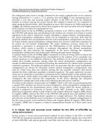
A key characteristic of symmetric OGSPs is rotational invariance. Rotational invariance of
groups of struts can be clearly understood with the help of Figure 3, Figure 4 and Figure 5.
Figure 3 represents a symmetric 8-strut OGSP, having M given as,
0.8660 0.0000 0.5000 0.1369 0.5969 0.2372
0.0000 0.8660 0.5000 0.5969 0.1369 0.2372
0.8660 0.0000 0.5000 0.1369 0.5969 0.2372
0.0000 0.8660 0.5000 0.5969 0.1369 0.2372
0.0000 0.5000 0.8660 1.0338 0.2372 0.1369
0.5000 0
& &
&
& & &
& & & &
& &
& .0000 0.8660 0.2372 1.0338 0.1369
0.0000 0.5000 0.8660 1.0338 0.2372 0.1369
0.5000 0.0000 0.8660 0.2372 1.0338 0.1369
(
)
*
+
*
+
*
+
*
+
*
+
*
+
*
+
&
*
+
*
+
&
*
+
&
*
+
*
+
,
-
It can be clearly seen that a strut failure in group 1 (Figure 4) or a strut failure in group 2
(Figure 5) causes the same effective change in manipulability.
Fig. 4. [4 4] cylindrical OGSP with one failure in group 1.
Quantifying and Optimizing Failure Tolerance of a Class of Parallel Manipulators
59
This prominent feature provides symmetric OGSPs with inherent optimal fault tolerant
manipulability under the occurrence of a failure. Furthermore, for symmetric OGSPs it is
possible to estimate post-fault reduction in manipulability by knowing the geometry. This is
explained in the following theorem.
!"#$%#&' <) For a [p q] (p
> 3,q 7 3 or q > 3,p 7 3) geometry, satisfying (A)- (F) in
Theorem 4, the relative manipulability after a single failure in group [p] is given by
j
r
1
where
j
r
1
is the optimal fault tolerant manipulability under one fault for an OGSP with [p p]
geometry. For the remaining cases of failure i.e. those corresponding to group [q], the
relative manipulability is given by
j
r
8
1
where
j
r
8
1
is the optimal fault tolerant manipulability
under one fault for an OGSP with [q q] geometry.
*%$$+, Consider a manipulator with [p q] (p
>
3,q
7
3 or q
>
3,p
7
3) geometry. Let
p
M
and
q
M denote the inverse Jacobian corresponding to each group. Then the composite
inverse Jacobian matrix
M
is given by
= .
p
q
M
M
M
(
)
*
+
,
-
(27)
Consider the case that a single link in group [p] fails. Then from rank one perturbation of a
matrix, we have
1
( ) = ( )(1 ( ) )
T T T T
f f
det M M det M M p M M p
&
8 8 8 8
.
(28)
where
f
p
represents the row of
p
M
corresponding to the link failure and
M
8
represents the
inverse Jacobian matrix after failure. Then,
1
( ) 1
= .
( ) (1 ( ) )
T
T T T
f f
det M M
det M M p M M p
&
8 8
8 8
.
(29)
Using the Matrix Inversion Lemma for the expression on the R.H.S. of equation (29)
1
( )
= 1 ( ( ) ).
( )
T
T T T
f f f f
T
det M M
p M M p p p
det M M
&
8
8
8 8
& .
(30)
Using the formulation as in equation (7), we have
1
( )
= 1 ( ( ) ).
( )
T
T T
f f
T
det M M
p M M p
det M M
&
8
8
&
(31)
Using conditions (A)- (F) given in Theorem 4, for a [p q] geometry with equal strut stiffness,
we have
1 2
= , = ,
i p i q
2 2 2 2
Parallel Manipulators, Towards New Applications
60
1 2
= , = ,
i p i q
x
x x x
1 2
= , = ,
i p i q
y y y y (32)
and
1
2 2 2 2 2 2
1 2 3 4 5 6
1 1 1 1 1 1
( ) = [ ].
T
M M diag
6 6 6 6 6 6
&
(33)
Note that
f
p also has a trigonometric parametrization given by Proposition 3.
= ,
p ij
p ij
p
T
f
ij p ij
ij p ij
p
S C
S S
C
p
S C C
C C S
S
2 3
2 3
2
3 2 3
3 2 3
2
(
)
*
+
*
+
*
+
*
+
*
+
.
*
+
*
+
& .
*
+
*
+
*
+
*
+
,
-
(34)
and substituting equation (32) in equations ((23)-(26)), we get
2 2 2 2
1 2
1
= = ( ),
2
p q
pS qS
2 2
6 6
. (35)
2 2
3 1
= ( ) 2 ,p q
6
6
. & (36)
2 2 2 2 2 2
4 5
2 2
1
= = ( ( ) ( )),
2
2 2
6 6
. . .
* * + +
* +
* ' ( ) + ' ( )
(37)
and
2 2 2 2 2
6
= ( ).
p q
p q
py S qy S
2 2
6
. (38)
Substituting equations ((35)-(38)) into equation(33), we get
1
)(
&
MM
T
in terms of design
parameters. Using this formulation of
1
)(
&
MM
T
into equation (31), then substituting equation
(34) in equation (31) and simplifying the complicated trigonometric expression, we get
1
( ) 3
= 1 ( ( ) ) = 1 .
( )
T
T T
f f
T
det M M
p M M p
det M M p
&
8
8
&
& (39)
It is important to note that this expression does not depend upon q or the particular
geometric parameters
ij
4
,
ij
x ,
ij
y and
ij
3
.
Quantifying and Optimizing Failure Tolerance of a Class of Parallel Manipulators
61
Note that the optimal fault tolerant manipulability for any [p p] manipulator is given by
equation (1) in Theorem 2. Hence,
(2 1)
6
1
2
6
3
= = 1 .
p
j
p
C
r
C p
&
& (40)
Since the choice of p does not cause any loss of generality, we have
(2 1)
6
1
2
6
3
= = 1 .
q
j
q
C
r
C q
&
8
&
(41)
#
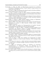
Results from this Theorem are plotted in Figure 6. Figure 6 depicts the change in values of
the relative manipulability, for different geometries, under the occurrence of one failure.
This Theorem proves the independence of the manipulability contributions of each
symmetric group of a two-group OGSPs which may have different number of struts in each
group. It is shown that within the group, any failure will give the same manipulability
reduction even in any two-group OGSPs. Figure 6 depicts the change in relative
manipulability under on failure, for symmetric OGSPs with different two–group
geometrical designs.
Fig. 5. [4 4] cylindrical OGSP with one failure in group 2.
Parallel Manipulators, Towards New Applications
62
Looking at Figure 6 it is now possible to estimate the level of post fault reduction in
manipulability of symmetric OGSPs. Corollary 6 proves that all two-group OGSPs ( i.e. with
[m m] (m
> 3) geometries ) possess optimal fault tolerant manipulability.
1$%$223%4' =)' Any 2s-strut OGSP with [s s] (s
> 3) geometry generated by Theorem 4
possesses optimal fault tolerant manipulability under one fault and its value is given by,
(2 1)
6
1
2
6
=
s
j
s
C
r
C
&
(42)
for all }{1,2, ,
1
2
Cj
s
# .
*%$$+, Consider a manipulator with [p q] (p
> 3,q 7 3 or q > 3,p 7 3) geometry. Substitute
q = p = s. Using Theorem 5,
(2 1)
6
1
2
6
=
s
j
s
C
r
C
&
(43)
for all
}{1,2, ,
1
2
Cj
s
# .
#
Fig. 6. Variation of the relative manipulability under a single failure, for various two group
geometries
Quantifying and Optimizing Failure Tolerance of a Class of Parallel Manipulators
63
For the particular case of a symmetric 8-strut OGSP introduced at the beginning of this
section,
1
= 0.5
j
r for all }{1,2, ,8
#
j .
This inherent property possessed by symmetric OGSPs can be put to a significant advantage
in design. Therorem 5 and Corollary (6) allow freedom of designing symmetric OGSPs with
a high value of nominal manipulability. For example, by Corollary (6) it is seen that an 8-
strut OGSP sustains any single-strut failure while retaining half of its nominal
manipulability. The optimal fault tolerant manipulability of symmetric OGSPs makes them
a suitable choice for critical applications where failure tolerance is necessary.
5.2 Singularities
While designing OGSPs with optimal fault tolerant manipulability, it is important to
identify symmetric OGSPs which may be rendered singular under the occurrence of one
fault. At the onset of singularity, unexpected motions are possible and the manipulator
cannot be controlled. This is highly undesirable and potentially destructive. The following
Theorem develops the necessary and sufficient condition to identify optimal fault tolerant
OGSPs with potential singularity problems.
!"#$%#&' >) Let
M
be the inverse Jacobian matrix of an OGSP with two groups. Then,
MM
i
T
i
is singular if and only if the group in which failure occurs has at most 3 struts.
The following lemma is necessary to prove the Theorem.
?#&&3'@)'For any
nm
$
matrix,
M
,
( ) = ( ).
T
rank M M rank M (44)
Proof of lemma: Clearly,
( ) ( ).
T
rank M M rank M% (45)
Let 0=MxM
T
for
n
x R
#
.
Then,
2
, = , = = 0.
T
M Mx x Mx Mx Mx9 : 9 : (46)
Hence,
0=Mx .
#
*%$$+'$+'!"#$%#&, Suppose that
MM
i
T
i
is singular. Then,
rank
( ) 5
T
i i
M M
%
.
Proposition 7 in (Aphale, 2006) determines the rank of
M
for an OGSP, having p groups
of struts:
Parallel Manipulators, Towards New Applications
64
1
( ) = ( ( ),6)
p
p
rank M min rank M
'
(47)
where
p
M denotes the inverse Jacobian matrix of the
th
p group.
In the context of failures, this proposition directly implies
1
( ) = ( ( ),6)
p
p
i f
rank M min rank M
'
(48)
where
M
p
f
denotes the inverse Jacobian matrix of the
th
p group having f strut failures
within the group. That is,
if =
'
.
Applying Lemma 8 to equation (48), we have
1
( ) = ( ( ), 6).
p
T p T p
i i f f
rank M M min ra nk M M
'
(49)
The nominal OGSP under consideration consists of two groups of struts. Hence,
2
=1
( ) = [ ( ),6]
T T
i i f f
e e
e
e e
rank M M min rank M M
'
(50)
where
1 2
=f f i. . Theorem 1 in (Aphale, 2006) establishes that the maximum rank of the
Jacobian matrix of a group of struts forming an OGSP is
3 . Therefore, MM
i
T
i
is singular if
the group in which any failure occurs has at most 3 struts. The converse is immediate.
#
:#&3%;,' It is worthwhile to note that unitarily equivalent Jacobian matrices (and inverse
Jacobian matrices) have the same manipulability, and it may be readily checked that all
single failure reduced inverse Jacobian matrices of a 2s OGSP with an [s s] geometry
generated by Theorem 4 are unitarily equivalent. This observation highlights the fact that
these designs produce manipulators with optimal fault tolerant manipulability.
5.3 Application example: air borne laser (ABL)
Currently, feasibility of missile defense using an aircraft equipped with a high energy laser
is being explored. At the concept level, the system uses a mirror inside the fuselage which
focusses a beam from a megawatt-class chemical laser. Optic and beam control systems
keeps the beam locked on a small supersonic target hundreds of kilometers away. It is
believed that ABL can destroy hostile theater ballistic missiles while they are still in the
highly vulnerable boost phase of flight before separation of the warheads. ABL can operate
above the clouds, where it is possible to autonomously detect and track missiles as they are
launched, using an onboard surveillance system. The defense system acquires the target,
then accurately points and fires the laser with sufficient energy to destroy the missile.
Airborne optical or electro-optical systems may be too large for all elements to be mounted
on a single integrating structure, other than the aircraft fuselage itself. An eight-legged six-
DOF OGSP (Octopod) is a perfect candidate to maintain the required alignment between
Quantifying and Optimizing Failure Tolerance of a Class of Parallel Manipulators
65
elements. However the various smaller integrating structures (benches) must still be isolated
from high-frequency airframe disturbances that could excite resonances outside the
bandwidth of the alignment control system. The combined active alignment and vibration
isolation functions must be performed by flight-weight components, which may have to
operate in a vacuum. The platform used must be able to perform the dual functions of low-
frequency alignment and high-frequency isolation (Keinholz, 1999).
The manipulability requirements for OGSPs intended for such an application are very
demanding and Aphale (Aphale, 2006) describes them in detail. It is also shown (Apahle,
2005) that OGSPs are capable of meeting the manipulability requirements, making them
suitable for the ABL application. Failure tolerance is imperative for this missile defense
application. Furthermore, it is difficult to predict specific failures at the design stage and as
such failure of any actuator is considered equally likely. If an equal reduction of
manipulability is desired under a failure of any strut, an OGSP with optimal fault tolerant
manipulability is an excellent choice.
6. Conclusions and future work
6.1 Conclusions
This work proves that for a certain class of parallel manipulators functioning about a single
point in its workspace, the mean squared relative manipulability over all possible cases of a
given number of actuator failures is always constant irrespective of the geometry of the
manipulator. In this context, optimal fault tolerant manipulability is defined and quantified
using a simple algebraic formulation. The definition is more suited to parallel manipulators
since they can retain kinematic stability under failures which constitute loss of actuators.
For micromanipulation, symmetric OGSPs can be designed to possess optimal
manipulability under actuator failures. OGSP geometries that may be rendered singular due
to faults can be identified and avoided. OGSPs with optimal fault tolerant manipulability
are highly suitable for critical applications since they retain a reasonable and equal fault
tolerant performance if any actuator fails. For example, Figure 3 illustrates a cylindrical [4 4]
OGSP that can be used in aerospace applications with ABL. These OGSPs will provide
operational reliability critical to the application.
6.2 Future work
Currently most OGSPs are seen to have a very small range of motion in the joint space. In
such scenarios, the assumption that the Jacobian matrix remains constant with respect to
time, is valid. Recent applications demand OGSPs with a larger range of motion. The
assumption of the Jacobian being constant does not hold validity in such cases. Investigating
the fault tolerant characteristics of a manipulator Jacobian which will take into account the
change with respect to time can be of great practical importance. It has recently been shown
(Roberts, Yu & Maciejewski, 2007) that, regardless of a manipulator's geometry or the
amount of kinematic redundancy present in a manipulator, no fully spatial manipulator
Jacobian can be equally fault tolerant to three or more joint failures. Due to these constraints
in generalization, it would be useful to formulate manipulator Jacobian matrices that
possess equal fault tolerance to specified scenarios involving multiple failures. In particular,
weights can be assigned to relative manipulability indices corresponding to multiple failure
Parallel Manipulators, Towards New Applications
66
scenarios and optimized values of relative manipulability can be obtained based on the
result derived in Theorem 1. Exploring the application of design and control techniques
devised for OGSPs in areas of medical robotics and haptic interfaces can be considered.
Robotics holds promise in standardized surgical procedures like eye surgery, knee surgery,
etc. The theory developed thus far can be applied efficiently in medical applications where
principles of robotics and computer vision combine towards a single objective. Multiple
finger grasp mechanisms and other parallel manipulators have been considered for such
applications. In these applications there is a need to withstand failures with almost no
degradation in performance. It is possible to transfer many theories and techniques related
to parallel manipulators to the analysis of multiple finger grasps with some modification.
It would be worthwhile to consider optimizing control for grasps such that fault tolerance
can be achieved. Internal force calculations have been done for parallel mechanisms like
multi-finger grasp mechanisms (Kerr & Roth, 1986). Internal force issues in other forms of
parallel manipulators have also been explored (Lebret, Liu & Lewis, 1993) (Hiller and
Schneider, 1997). Literature on the internal forces generated in GSPs is limited. OGSPs being
a very recently defined class haven't been explored with respect to the internal forces they
generate and need to withstand. With redundancy comes more number of actuators than the
required minimum and a large number of constraints associated with them. Under failures,
internal forces will be a major factor in the dynamics and control of OGSPs. Generating
OGSPs that provide equal tolerance to failures with respect to the dynamic manipulability
index seems feasible.
Finally, it is most important to recognize that the main contribution of this work is a
combinatorial result in linear algebra. Numerous systems in various disciplines can be
modeled by matrices. For instance, matrices are used to model power transmission and
distribution systems. In matrix models where failures amount to elimination of rows and
(or) columns, the theory of fault tolerance developed thus far would be useful and
worthwhile extending.
7. References
Aphale, S. (2006). 6%'#/"#"/* +&(7+/+"28* /+9/7:'(%;2&(* <82(,+&.'* ;#(7* &+=9'(* ,298(* (+8%&2">%,
ProQuest / UMI, ISBN-10: 0542313596, Ph.D. Dissertation0*University of Wyoming,
Laramie, WY.
Baillieul, J. (1996). Avoiding obstacles and resolving redundancy, ?&+>%%@# "/'* +,* ABBB*
A"(%&"2(#+"28*C+",%&%">%*+"*D+=+(#>'* 2"@*59(+.2(#+", pp. 1698 – 1703, San Francisco,
CA., April 1990.
Hiller, M. & Schneider, M. (1997). Modeling, simulation and control of flexible
manipulators, B9&+<%2"*E+9&"28*+,*F%>72"#>', vol. 16, 1997, page numbers 127-150.
Hollerbach, J. M. & Suh, K. C. (1987). Redundancy resolution of manipulators through
torque optimization, ABBB* E+9&"28* +,* D+=+(#>'* 2"@* 59(+.2(#+", vol. RA-3, no. 4,
August 1987, page numbers 308-316.
Kerr, J. & Roth, B. (1986). Analysis of multifingered hands, A"(%&"2(#+"28* E+9&"28* +,* D+=+(#>*
D%'%2&>7, vol. 4, no. 4, 1986, page numbers 3-17.
Quantifying and Optimizing Failure Tolerance of a Class of Parallel Manipulators
67
Kim H. W. ;Lee J. H. ; Yi, B. J & Suh I. H. (2004). Singularity-free load distribution algorithms
for a 6 dof parallel haptic device, ?&+>%%@#"/'* +,* ABBB* A"(%&"2(#+"28* C+",%&%">%* +"*
D+=+(#>'*2"@*59(+.2(#+", pp. 298-304, New Orleans, LA., May 2004.
Kock, S. & Schumacher W. (1998). A parallel x-y manipulator with actuation redundancy
for high speed and active stiffness applications, ?&+>%%@#"/'* +,* ABBB* A"(%&"2(#+"28*
C+",%&%">%*+"*D+=+(#>'*2"@*59(+.2(#+", , pp. 2295-2300, Leuven, Belgium, May 1998.
Lebret, G.; Liu, K. & Lewis, F. L. Dynamic analysis and control of a stewart platform
manipulator, Jo9&"28*+,*D+=+(#>*4)'(%.', vol. 10, no. 5, 1993, page numbers 629-655.
Lewis, C. L. & Maciejewski, A. A. (1992). Dexterity optimization of kinematically redundant
manipulators in presence of faults, ?&+>%%@#"/'*+,*G+9&(7*A"(%&"2(#+"28*4).<+'#9.*+"*
D+=+(#>'*2"@*F2"9,2>(9&#"/, pp. 279-284, Santa Fe, NM., November 1992.
Maciejewski, A. A. (1990). Fault tolerant properties of kinematically redundant
manipulators, ?&+>%%@#"/'*+,*ABBB*A"(%&"2(#+"28*C+",%&%">%*+"*D+=+(#>'*2"@*59(+.2(#+",
pp. 638-642, Cincinnati, OH., May 1990.
McInroy, J. E. ; O’Brien, J. F. & Neat, G. W. (1999). Precise, fault-tolerant pointing using a
stewart platform, ABBBH54FB* I&2"'2>(#+"'* +"* F%>72(&+"#>', vol. 4, no. 1, March
1999, page numbers 91-95.
McInroy, J. E. & Jafari, F. (2006). Finding symmetric orthogonal gough-stewart platforms,
ABBB* I&2"'2>(#+"'* +"* D+=+(#>'* 2"@* 59(+.2(#+", vol. 22, no. 5, October 2006, page
numbers 880-889.
Paredis, C. J. J. ; Au, W. K. F. & Khosla, P. K. (1994). Kinematic design of fault tolerant
manipulators, C+.<9(%&'*B8%>(&#>28*B"//30 vol. 20, no. 3, 1994, page numbers 211-220.
Roberts, R. G. & Maciejewski, A. A. (1996). A local measure of fault tolerance for
kinematically redundant manipulators, ABBB* I&2"'2>(#+"'* +"* D+=+(#>'* 2"@*
59(+.2(#+", vol. 12, no. 4, August 1996, page numbers 543-552.
Roberts, R. G.; Yu, H. G. & Maciejewski, A. A. (2007). Characterizing Optimally Fault-
Tolerant Manipulators Based on Relative Manipulability Indices,*JKKL*A"(%&"2(#+"28*
C+",%&%">%*+"*A"(%88#/%"(*D+=+('*2"@* 4)'(%.'*MADN4*JKKLO0 pp. 3925-3930, San Diego,
CA., Oct. 29 - Nov. 2, 2007.
Stewart, D. (1966). A platform with six degrees of freedom, ?&+>%%@#"/'* +,* A"'(#(9(#+"* +,*
F%>72"#>28*B"/#"%%&', Part 1, vol. 180, no. 15, 1966, page numbers 371-378.
Ting, Y. ; Tosunoglu, S. & Tesar, D. (1993). A control structure for fault-tolerant operation of
robotic manipulators, ?&+>%%@#"/'* +,* ABBB* A"(%&"2(#+"28* C+",%&%">%* +"* D+ =+(#>'* 2"@*
59(+.2(#+", , pp. 684-690, Atlanta, GA., May 1993.
Ukidve, C. S. ; McInroy, J. E. & Jafari, F. (2006). Orthogonal Gough-Stewart Platforms with
optimal fault tolerant manipulability, ?&+>%%@#"/'*+,*ABBB*A"(%&"2(#+"28*C+",%&%">%*+" *
D+=+(#>'*2"@*59(+.2(#+", pp. 3801-3806, Orlando, FL., May 2006.
Wapler, M. ; Urban, V.; Weisener, T.; Stallkamp, J. ; Durr, M. & Hiller, A. (2003). A stewart
platform for precision surgery, I&2"'2>(#+"'* +,* (7%* A"'(#(9(%* +,* F%2'9&%.%"(* 2"@*
C+"(&+8, vol. 25, no. 4, 2003, page numbers 329-334.
Parallel Manipulators, Towards New Applications
68
Wen, J. T Y. & Wilfinger, L. S. (1999). Kinematic manipulability of general constrained rigid
multibody systems, ABBB*I&2"'2>(#+"'*+"*D+=+(#>' *2"@*59(+.2(#+", vol. 15, no. 3, June
1999, page numbers 558-567.
Yoshikawa, T. (1985). Manipulability of robotic mechanisms, A"(%&"2(#+"28*E+9&"28*+,*D+=+(#>'*
D%'%2&>7, vol. 4, no. 2, 1985, page numbers 3-9.
4
Dynamic Model of a 6-dof Parallel Manipulator
Using the Generalized Momentum Approach
António M. Lopes and Fernando Almeida
UISPA – Unidade de Integração de Sistemas e Processos Automatizados,
Universidade do Porto, Faculdade de Engenharia
Portugal
1. Introduction
The dynamic model of a mechanical system relates the time evolution of its configuration
(position, velocity and acceleration) with the forces and torques acting upon it. The inverse
dynamic model is important for system control while the direct model is used for system
simulation.
Serial structure manipulator dynamic modelling is a well established subject. So, recent
developments have been oriented towards the improvement of numerical efficiency
enabling their use in real-time control algorithms (Lilly, 1993; Naudet, 2003; Mata, 2002; Lee,
2005; Featherstone, 2000). Parallel structure manipulators present a more complex problem,
and, usually, the model algorithms cannot be generalized. When used in a real-time control
framework the resulting models must be simplified as they usually demand a very high
computational effort.
The dynamic model of a parallel manipulator when operated in free space can be
mathematically represented, in the Cartesian space, by a system of nonlinear differential
equations that may be written in matrix form as
(
)
(
)
(
)
fxGxxxVxxI
=
+
⋅
+
⋅
,
(1)
()
xI being the inertia matrix,
(
)
xxV
, the Coriolis and centripetal terms matrix,
()
xG a vector
of gravitational generalized forces, x the generalized position of the mobile platform or end-
effector and f the controlled generalized force applied on the end-effector:
(
)
τxJf ⋅=
T
(2)
where τ is the generalized force developed by the actuators and J(x) is a jacobian matrix.
The dynamic model of a parallel manipulator is usually developed following one of two
approaches (Callegari, 2006): the Newton-Euler or the Lagrange methods. The Newton-
Euler approach uses the free body diagrams of the rigid bodies. The Newton-Euler equation
is applied to each single body and all forces and torques acting on it are obtained. Do and
Yang, and Reboulet and Berthomieu use this method on the dynamic modelling of a Stewart
platform (Do & Yang, 1988; Reboulet & Berthomieu, 1991). They achieve their result
introducing some simplifications on the legs models. Ji (Ji, 1994) presents a study on the
Parallel Manipulators, Towards New Applications
70
influence of leg inertia on the dynamic model of a Stewart platform. Mouly (Mouly, 1993)
presents a simplified model for a variation of the Stewart platform, only taking into account
the mobile platform. Dasgupta and Mruthyunjaya used the Newton-Euler approach to
develop a closed-form dynamic model of the Stewart platform (Dasgupta & Mruthyunjaya,
1998). This method was also used by other researchers (Dasgupta & Choudhury, 1999;
Khalil & Ibrahim, 2007; Riebe & Ulbrich, 2003; Khalil & Guegan, 2004; Guo & Li, 2006;
Carvalho & Ceccarelli, 2001).
The Lagrange method describes the dynamics of a mechanical system from the concepts of
work and energy. This method enables a systematic approach to the motion equations of
any mechanical system. Nguyen and Pooran use this method to model a Stewart platform,
modelling the legs as point masses (Nguyen & Pooran, 1989). Other researchers follow an
approach similar to the one used by Nguyen and Pooran, but trying to increase the physical
meaning of the obtained mathematical expressions (Liu et al., 1993; Lebret et al., 1993). Geng
and co-authors (Geng et al., 1992) used the Lagrange’s method to develop the equations of
motion for a class of Stewart platforms. Some simplifying assumptions regarding the
manipulator geometry and inertia distribution were considered. Lagrange’s method was
also used by others (Bhattacharya et al., 1998; Gregório & Parenti-Castelli, 2004; Caccavale et
al., 2003).
Unfortunately the dynamic models obtained from these classical approaches usually present
high computational loads. Therefore, alternative methods have been searched, namely the
ones based on the principle of virtual work (Wang & Gosselin, 1998; Tsai, 2000; Li & Xu,
2005; Staicu et al., 2007), and screw theory (Gallardo et al., 2003).
In this paper the authors present a new approach to the problem of obtaining the dynamic
model of a six degrees-of-freedom (dof) parallel manipulator: the use of the generalized
momentum concept.
The manipulator under study may be seen as a variation of the Stewart platform, with the
uniqueness of having all its actuators fixed to the base platform and only moving in a
direction perpendicular to that base (Merlet & Gosselin, 1991). A prototype of this
manipulator, the Robotic Controlled Impedance Device (RCID), was developed aiming a
broad set of force-impedance control tasks. The obtained dynamic model requires a
considerably lower computational effort than the one resulting from the use of classical
Lagrange method.
This paper is organized as follows. Section 2 describes the RCID parallel manipulator.
Section 3 presents the manipulator dynamic model using the generalized momentum
approach. In section 4 the computational effort of the RCID dynamic model is evaluated.
Conclusions are drawn in section 5.
2. Parallel manipulator structure
The RCID is a 6-dof parallel mini-manipulator (Figure 1). Parallel manipulators are well
known because of their high dynamic performances and low positioning errors (Chablat et
al., 2004; Merlet, 2006). In the last few years parallel manipulators have attracted great
attention from researchers involved with robot manipulators (Bruzzone, 2005), robotic end
effectors (Vischer & Clavel, 2000), robotic devices for high-precision robotic tasks (Pernette,
et al., 2000), machine-tools (Zhang & Gosselin, 2002), simulators (Kim et al., 2002), and
haptic devices (Constantinescu et al., 2005).
Dynamic Model of a 6-dof Parallel Manipulator Using the Generalized Momentum Approach
71
Figure 1. Photography of the RCID
The mechanical structure of the RCID comprises a fixed (base) platform and a moving
(payload) platform, linked together by six independent, identical, open kinematic chains
(Figure 2). Each chain comprises two links: the first link (linear actuator) is always normal to
the base and has a variable length, l
i
, with one of its ends fixed to the base and the other one
attached, by a universal joint, to the second link; the second link (fixed-length link) has a
fixed length, L, and is attached to the payload platform by a spherical joint. Points B
i
and P
i
are the connecting points to the base and payload platforms. They are located at the vertices
of two semi-regular hexagons, inscribed in circumferences of radius r
B
and r
P
, that are
coplanar with the base and payload platforms (Figure 3).
x
B
x
P
z
B
z
P
B
6
B
5
B
4
B
3
B
2
L
B
P
B
1
y
B
y
P
l
1
l
2
l
3
l
4
l
5
l
6
P
1
P
2
P
3
P
4
P
5
P
6
Base
Payload
platform
A
ctuator
Figure 2. A schematic view of the RCID mechanical structure
For kinematic modelling purposes a right-handed reference frame {B} is attached to the base.
Its origin is located at point B, the centroid of the base. Axis x
B
is normal to the line
connecting points B
1
and B
6
and axis z
B
is normal to the base, pointing towards the payload
platform. The angles between points B
1
and B
3
and points B
3
and B
5
are set to 120º. The
Parallel Manipulators, Towards New Applications
72
separation angles between points B
1
and B
6
, B
2
and B
3
, and B
4
and B
5
are denoted by 2
φ
B
(Figure 3). In a similar way, a right-handed frame {P} is assigned to the payload platform. Its
origin is located at point P, the centroid of the payload platform. Axis x
P
is normal to the line
connecting points P
1
and P
6
and axis z
P
is normal to the payload platform, pointing in a
direction opposite to the base. The angles between points P
1
and P
3
and points P
3
and P
5
are
set to 120º. The separation angles between points P
1
and P
2
, P
3
and P
4
, and P
5
and P
6
are
denoted by 2
φ
P
(Figure 3). The main kinematic RCID parameters have been adjusted in
order to maximize the manipulator dexterity (Lopes & Almeida, 1996) within a prescribed
workspace: the payload platform may be positioned anywhere inside a sphere of radius 10
mm (centred at a point of the line witch contains axis z
B
) and rotate ±15º around any axis
containing the payload platform centre. This requires the actuators displacement of Δl
i
= 70
mm approximately. The main kinematic parameters values are shown in Table 1.
B
1
B
2
B
3
B
4
B
5
B
6
r
B
120º
120º
φ
Β
φ
Β
φ
Β
φ
Β
φ
Β
φ
Β
x
B
y
B
B
P
1
P
2
P
3
P
4
P
5
P
6
P
x
P
y
P
r
P
φ
P
φ
P
φ
P
φ
P
φ
P
φ
P
60º
60º
Figure 3. Position of the connecting points to the base and payload platforms
Parameter Value
r
B
80 mm
r
P
40 mm
φ
B
15º
φ
P
0º
L
97.98 mm
Δl
i
70 mm
Table 1. RCID main kinematic parameters
The RCID prototype is powered by six DC rotary motors (28D11-222E.2, from
PORTESCAP). A ball-screw based transmission converts motor rotation to actuator vertical
translation. Linear position and acceleration of each actuator are measured, as well as
Cartesian forces and moments applied to the payload platform. Actuators acceleration
relative to the base platform is given by the difference between the signals of each actuator
accelerometer and the base accelerometer. Potentiometric displacement transducers (RC13-
Dynamic Model of a 6-dof Parallel Manipulator Using the Generalized Momentum Approach
73
100 Bauform M, from MEGATRON), accelerometers (FA-208-15, Range ±5g, from
EUROSENSOR) and a six-axis force/torque transducer (67M25A-I40, 200N, from JR3) are
used.
The RCID mechanical structure has been produced using, whenever possible, standard
mechanical components. Nevertheless, several small parts have been purposely designed
and manufactured. Physically, the RCID mechanical structure comprises two fixed identical
parallel platforms, which have been carefully aligned both angular and axially. The bottom
platform supports the six DC electric motors. It also supports a flange to connect the RCID
to an industrial robot. The ball-screw transmissions (from STAR), the linear actuators, and
the potentiometric displacement transducers are located between the two fixed platforms.
The universal joints are steel standard parts (from HUCO) using needle roller bearings. The
fixed-length links and the double spherical joints have been purposely designed and
manufactured. The payload platform supports the force/torque transducer, which has an
ISO interface that may be used to attach a tool. The RCID maximal height is approximately
530 mm (when the payload platform is at its farthest position). Maximum diameter is
approximately 265 mm (corresponding to the fixed platforms diameter), and total mass is
about 9.7 kg. Maximum payload platform velocity along vertical direction is 220 mm/s and
maximum payload capability is 5 kg.
For kinematic modelling purposes, and attaching frames {P} and {B} to the payload and base
platforms, respectively, the generalized position of frame {P} relative to frame {B} may be
represented by the vector:
[]
() ()
[
]
T
T
E
oP
BT
B
posP
B
T
PPPPPP
EB
P
B
zyx xxx ==
ϕθψ
|
(3)
where
()
[
]
T
PPP
B
posP
B
zyx=x is the position of the origin of frame {P} relative to frame {B},
and
()
[]
T
PPP
E
oP
B
ϕθψ
=x defines an Euler angle system representing orientation of frame
{P} relative to {B}. The Euler angles constitute a minimal representation of a rigid body
orientation (only three parameters). There exist twelve different Euler angle systems,
according to the sequence of the performed elemental rotations (Sciavicco & Siciliano, 1996).
The used Euler angle system corresponds to the basic rotations (Vukobratovic & Kircanski,
1986):
ψ
P
about z
P
;
θ
P
about the rotated axis y
P’
; and
ϕ
P
about the rotated axis x
P’’
. This is
equivalent to a rotation of
ϕ
P
about x
B
, followed by a rotation of
θ
P
about y
B
, and a rotation
of
ψ
P
about z
B
. The rotation matrix is given by:
⎥
⎥
⎥
⎦
⎤
⎢
⎢
⎢
⎣
⎡
−
−+
+−
=
PPPPP
PPPPPPPPPPPP
PPPPPPPPPPPP
P
B
CCSCS
SCCSSCCSSSCS
SSCSCCSSSCCC
ϕθϕθθ
ϕψϕθψϕψϕθψθψ
ϕψϕθψϕψϕθψθψ
R (4)
S(⋅) and C(⋅) correspond to the sine and cosine functions, respectively. The chosen Euler
angle system introduces a representation singularity at
θ
P
= 90º, that is, outside the allowed
RCID workspace.
The position and velocity kinematic models of the RCID are well known (Merlet & Gosselin,
1991), being obtainable from the geometrical analysis of the kinematics chains. The velocity
kinematics is represented by the Euler angles jacobian matrix, J
E
, or the kinematics jacobian,
Parallel Manipulators, Towards New Applications
74
J
C
. These jacobians relate the velocities of the active joints, the actuators, with the
generalized velocity of the mobile platform:
()
⎥
⎥
⎦
⎤
⎢
⎢
⎣
⎡
⋅=⋅=
E
oP
B
B
posP
B
E
EB
P
B
E
)(
|
x
x
JxJl
(5)
()
⎥
⎥
⎦
⎤
⎢
⎢
⎣
⎡
⋅=⋅=
B
P
B
B
posP
B
C
B
P
B
C
ω
x
JxJl
(6)
with
[
]
T
lll
621
"
=l (7)
()
E
oP
B
A
B
P
B
xJω
⋅=
(8)
and (Vukobratovic & Kircanski, 1986)
⎥
⎥
⎥
⎦
⎤
⎢
⎢
⎢
⎣
⎡
−
−
=
P
PPP
PPP
A
S
SCC
CCS
θ
ψθψ
ψθψ
01
0
0
J (9)
Vectors
()
B
P
B
B
posP
B
vx ≡
and
B
P
B
ω
represent, by that order, the linear and angular velocity
of the mobile platform relative to {B}, and
()
E
oP
B
x
represents the Euler angles time
derivative.
3. Dynamic modelling using the generalized momentum approach
The generalized momentum of a rigid body, q
c
, may be obtained from the following general
expression:
ccc
uIq
⋅
=
(10)
Vector u
c
represents the generalized velocity (linear and angular) of the body and I
c
is its
inertia matrix. Vectors q
c
and u
c
and inertia matrix I
c
must be expressed in the same frame of
reference.
Equation (10) may also be written as:
⎥
⎦
⎤
⎢
⎣
⎡
⋅
⎥
⎦
⎤
⎢
⎣
⎡
=
⎥
⎦
⎤
⎢
⎣
⎡
=
c
c
rotc
trac
c
c
c
ω
v
I0
0I
H
Q
q
)(
)(
(11)
where Q
c
is the linear momentum vector due to rigid body translation and H
c
is the angular
momentum vector due to body rotation. I
c(tra)
is the translational inertia matrix and I
c(rot)
the
rotational inertia matrix. v
c
and ω
c
are the body linear and angular velocities.
The inertial component of the generalized force acting on the body can be obtained from the
time derivative of equation (10):
Dynamic Model of a 6-dof Parallel Manipulator Using the Generalized Momentum Approach
75
()
cccccinec
uIuIqf
⋅+⋅== (12)
with force and momentum expressed in the same frame.
3.1 Mobile platform modeling
The linear momentum of the mobile platform, written in frame {B},
B
P
Q , may be obtained
from the following expression:
B
P
B
traP
B
P
B
P
B
P
m vIvQ ⋅=⋅=
)(
(13)
I
P(tra)
is the translational inertia matrix of the mobile platform,
⎥
⎥
⎥
⎦
⎤
⎢
⎢
⎢
⎣
⎡
=
P
P
P
traP
m
m
m
00
00
00
)(
I (14)
m
P
being its mass.
The angular momentum,
B
P
H , also written in frame {B}, is:
B
P
B
B
rotP
B
P
ωIH ⋅=
)(
(15)
B
rotP
)(
I represents the rotational inertia matrix of the mobile platform, expressed in the base
frame {B}.
The inertia matrix of a rigid body is constant when expressed in a frame that is fixed relative
to that body. Furthermore if the frame axes coincide with the principal directions of inertia
of the body, then all inertia products are zero and the inertia matrix is diagonal. Therefore,
the rotational inertia matrix of the mobile platform when expressed in frame {P} may be
written as:
⎥
⎥
⎥
⎦
⎤
⎢
⎢
⎢
⎣
⎡
=
zz
yy
xx
P
P
P
P
rotP
I
I
I
00
00
00
)(
I
(16)
This inertia matrix can be written in frame {B} using the following transformation (Torby,
1984):
T
P
B
P
rotP
P
B
B
rotP
RIRI ⋅⋅=
)()(
(17)
The generalized momentum of the mobile platform, expressed in frame {B}, can be obtained
from the simultaneous use of equations (13) and (15):
⎥
⎥
⎦
⎤
⎢
⎢
⎣
⎡
⋅
⎥
⎦
⎤
⎢
⎣
⎡
=
B
P
B
B
P
B
B
rotP
traP
B
P
ω
v
I0
0I
q
)(
)(
(18)
where
Parallel Manipulators, Towards New Applications
76
⎥
⎦
⎤
⎢
⎣
⎡
=
B
rotP
traP
B
P
)(
)(
I0
0I
I
(19)
is the mobile platform inertia matrix written in the base frame {B}.
The combination of equations (8) and (15) results into:
()
E
oP
B
A
B
rotP
B
P
xJIH
⋅⋅=
)(
(20)
Accordingly, equation (18) may be rewritten as:
()
⎥
⎥
⎦
⎤
⎢
⎢
⎣
⎡
⋅
⎥
⎦
⎤
⎢
⎣
⎡
ℑ
⋅
⎥
⎦
⎤
⎢
⎣
⎡
=
E
oP
B
B
P
B
A
B
rotP
traP
B
P
x
v
J
I0
0I
q
0
0
)(
)(
(21)
EB
P
B
B
P
B
P
|
xTIq
⋅⋅= (22)
T being a matrix transformation defined by:
⎥
⎦
⎤
⎢
⎣
⎡
ℑ
=
A
J0
0
T
(23)
The time derivative of equation (22) results into:
()
(
)
EB
P
B
B
P
EB
P
B
B
P
B
P
B
ineP
P
dt
d
||
xTIxTIqf
⋅⋅+⋅⋅==
(24)
()
B
ineP
P
f
is the inertial component of the generalized force acting on {P} due to the mobile
platform motion, expressed in frame {B}. The corresponding actuating forces,
τ
P(ine)
, may be
computed from the following relation:
() ()
B
ineP
PT
CineP
fJτ ⋅=
−
(25)
The same inertial component of the generalized force acting on {P} due to the mobile
platform motion, but now expressed using the Euler angles system, can be found by pre-
multiplying equation (24) by T
T
:
() ()
(
)
EB
P
B
B
P
T
EB
P
B
B
P
T
B
ineP
PT
EB
ineP
P
dt
d
|||
xTITxTITfTf
⋅⋅⋅+⋅⋅⋅=⋅=
(26)
and, in a similar way, the corresponding actuating forces, τ
P(ine)
, may be computed from the
relation:
() ()
EB
ineP
PT
EineP
|
fJτ ⋅=
−
(27)
This implies that:
()
() ()
[
]
T
T
E
ineP
PT
B
ineP
P
EB
ineP
P
MFf =
|
(28)
Dynamic Model of a 6-dof Parallel Manipulator Using the Generalized Momentum Approach
77
Vector
()
B
ineP
P
F represents the force acting on the centre of mass of the mobile platform,
expressed in the base frame, {B}, and vector
()
E
ineP
P
M
represents the moment acting on the
mobile platform, expressed using the Euler angles system. Thus, this representation does
not allow a clear physical interpretation of
()
E
ineP
P
M .
On the other hand, it can be said that
() () ()
[
]
T
T
B
ineP
PT
B
ineP
P
B
ineP
P
MFf = (29)
where
() ()
E
ineP
PT
A
B
ineP
P
MJM ⋅=
−
represents the moment acting on the mobile platform
expressed, this time, in the base frame.
From equation (24) it can be concluded that two matrices playing the roles of the inertia
matrix and the Coriolis and centripetal terms matrix are:
TI ⋅
B
P
(30)
(
)
TI ⋅
B
P
dt
d
(31)
It must be emphasized that these matrices do not have the properties of inertia or Coriolis
and centripetal terms matrices and therefore should not, strictly, be named as such.
Nevertheless, throughout the paper the names “inertia matrix” and “Coriolis and centripetal
terms matrix” may be used if there is no risk of misunderstanding.
On the other hand, from equation (26), the inertia matrix and the Coriolis and centripetal
terms matrix, expressed in the Euler angles system, are:
TITI ⋅⋅=
B
P
T
E
P
(32)
(
)
TITV ⋅⋅=
B
P
T
E
P
dt
d
(33)
3.2 Actuators modeling
As the RCID actuators can only move perpendicularly to the base plane, their angular
velocity relative to frame {B} is always zero. So, each actuator can be modelled as a point
mass located at its centre of mass.
The linear momentum of each actuator along direction z
B
,
i
A
q , is obtainable from:
iAA
lmq
i
⋅=
(34)
where m
A
is the mass and
i
l
the velocity of actuator i.
Simultaneously considering the six actuators results into:
lq
#
#
⋅=
⎥
⎥
⎥
⎥
⎥
⎦
⎤
⎢
⎢
⎢
⎢
⎢
⎣
⎡
=
⎥
⎥
⎥
⎥
⎥
⎦
⎤
⎢
⎢
⎢
⎢
⎢
⎣
⎡
=
AA
A
A
A
A
m
l
l
l
m
q
q
q
6
2
1
6
2
1
(35)