Sensors, Focus on Tactile, Force and Stress Sensors 2011 Part 7 pot
Bạn đang xem bản rút gọn của tài liệu. Xem và tải ngay bản đầy đủ của tài liệu tại đây (471.43 KB, 30 trang )
Study on Dynamic Characteristics of Six-axis Wrist Force/torque Sensor
171
+
y(k-1)
u(k-m)
u(k-1)
y(k-n)
e(k)
y(k)
u(k)
u'(k)
W
i
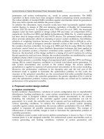
Fig. 4-1 Design schematic of dynamic compensating device by FLANN
Where
i
W are the weights of the network, i.e. the model coefficients of the dynamic
compensation device, k is the point number of data.
The error is
'
() () ()ek uk u k=− (4.2)
The weight updating equations are given by
(1) () ()( )
nn
Wk Wk ekyk n
α
+
=+ − (
n
=0,1,2) (4.3)
22
(1) () ()( 2)
mm
Wk Wk ekukm
α
++
+
=+ −− ( m =1,2) (4.4)
where the learning constant
α
governs the stability and the rate of convergence. If the
value of
α
is too small, the speed of convergence is slow. If the value of
α
is too large, the
result may diverge. Generally speaking, the value of
α
varies from 0 to 1. The simulation
results show that it is suitable to set
α
about 0.1 for our case. After training of many times,
when the average mean square error attains a minimum value, the obtained weights are the
coefficients of the compensation device.
At the beginning of the on-line compensation, we suppose
'
() ()uk yk= , where k =0,1,2,
and ()uk is replaced by the output feedback
'
()uk. The equation of dynamic compensating is
'
()uk
=
''
01 2 3 4
() (1) ( 2) (1) (2)Wyk Wyk Wyk Wu k Wu k
+
−+ − + −+ −
( k ≥ 3) (4.5)
It should be noted that the designing equations mentioned above are used for one channel
of the wrist force sensor, and the equations for other channels are on the analogy of the
above equations.
4.2 Design procedure of dynamic compensation device
1. An ideal equivalent measurement system including the sensor and the dynamic
compensation device is constructed by adjustment the damp ratio and natural
frequency.
2. The exciting signal (constructed or practical) is inputted, and the dynamic response of
the equivalent measurement system is obtained.
3. Based on the dynamic responses of both the wrist force sensor and the equivalent
measurement system, a dynamic compensation device is designed.
Sensors, Focus on Tactile, Force and Stress Sensors
172
4. The dynamic response of the wrist force sensor is corrected.
5. In the light of the effects of compensation, the dynamic compensation devices are
improved until the requirement is satisfied.
4.3 Dynamic compensation system
1. Realization of the dynamic compensation system
This dynamic compensation system consists of six dynamic compensating devices for six
directions of the wrist force sensor, and the data acquisition, decoupling, dynamic
compensating and output can be performed with the system.
Fig. 4-2 shows the hardware block of the dynamic compensation system. This system mainly
includes an ADSP-2181 EZ-KIT Lite, an analog input part, an output part and the logic
control circuit. The analog input part consists of eight sampling and holding circuits (S/H),
a multiplexer (MUX), an amplifier (AMP) and an analog-to-digital converter (A/D). The
output part contains six digital to analog converters (D/A) and six RC filters. The logic
control circuit mainly consists of a decoder. The ADSP-2181 EZ-KIT Lite board is a minimal
implementation system of an ADSP-2181 processor designed by ADI Corporation, and
mainly includes an ADSP-2181, an EPROM and a serial communication port. The outputs of
eight channels of the wrist force sensor are connected to the inputs of eight S/Hs. Whether
the sampling mode is switched to the holding mode is controlled by ADSP-2181 based on
the sampling frequency. Eight channel signals are switched and connected sequentially by
the MUX, amplified by the AMP, and sent to the A/D. A busy pin of the A/D is connected
to a programmable input/output pin. The ADSP-2181 determines the reading time
according to the status of the busy pin.
8 S/H MUX AMP
A/D6 D/A
ADSP-2181
EZ-Kit Lite
Logic
Control
Input
Output
Fig. 4-2 Schematic block digram of dynamic compensating system
After eight channel signals are acquired by the ADSP-2181 at the same time, they are
decoupled statically to be six channel signals, i.e.
x
F
,
y
F
,
z
F
,
x
M
,
y
M
and
z
M
. Then the
six channel signals are compensated dynamically, and output by six D/As. Under the
program control of the ADSP-2181, the logic control circuit determines the chip selection of
A/D and D/A.
The software design of the system includes a data acquisition module, a data processing
module and a result output module. The sampling interval of the system is determined by
Study on Dynamic Characteristics of Six-axis Wrist Force/torque Sensor
173
the interrupt of the timer, and is 50
s
μ
or 250
s
μ
so as to sample enough data in the
sensor’s dynamic response process. When the power is applied to the system, it starts
initialization, and then enters the state of waiting for interruption. When the timer generates
an interruption, the system begins a circle of data acquisition, processing and output. In one
sampling period, the eight channel signals of the same time are acquired, decoupled
statically to become six channel signals, then compensated dynamically, and output. The
system runs the program continuously in this way.
2. Experimental results of the dynamic compensation system
The dynamic compensation system was connected to the wrist force sensor, and the
dynamic experiments of step response were conducted to verify the effectiveness of
dynamic compensation. The dynamic compensation results of six channels of a wrist force
sensor (No. 3) are shown in Fig. 4-3 (a)~(f). In figures, curve 1 was the dynamic response of
the wrist force sensor, and curve 2 is the output of the dynamic compensation system. The
compensation coefficients of six channels were shown in Table II. The experimental results
indicate that the adjusting time (within
±
10 error of steady status) of dynamic response of
the wrist force sensor is less than 5
ms , i. e. the adjusting time is reduced to less than 25%,
and the dynamic performance indexes is greatly improved via dynamic compensation.
(a) Channel
x
F
(b) Channel
y
F
(c) Channel
z
F
(d) Channel
x
M
Sensors, Focus on Tactile, Force and Stress Sensors
174
(e) Channel
y
M
(f) Channel
z
M
Fig. 4-3 Experiment results (1) dynamic response of sensor, (2) output of dynamic
compensating system.
x
F
y
F
z
F
x
M
y
M
z
M
0
W
0.264231 0.959694 0.777428 0.251256 0.359567 0.920652
1
W
-0.525321 -1.915169 -1.541528 -0.4987790 -0.713234 -1.818204
2
W
0.261612 0.957071 0.772072 0.248014 0.354212 0.909576
3
W
1.966720 1.956619 1.871834 1.969605 1.970583 1.846556
4
W
-0.967239 -0.958209 -0.879801 -0.970085 -0.971131 -0.858568
Table 4-1 Coefficients of dynamic compensating system
5. Dynamic decoupling-compensation
There are dynamic couples among various channels of multi-axis force and torque sensors
because the elastic body of the sensor is an integer structure and the interaction of various
channels cannot be avoided completely. In addition, due to their small damped ratio and
low natural frequency, the sensors dynamic response is slow, and the time to reach steady
state is long. Both dynamic coupling and slow dynamic response are two main factors
affecting the dynamic performances of sensors. We proposed the dynamic compensating
and decoupling methods of multi-force sensors, constructed four types of dynamic
decoupling and compensating networks, gave the design procedures and determines the
order and parameters of the networks. The parameters of the networks are determined
using the method based on FLANN. The dynamic decoupling and compensating results of a
wrist force sensor have proved the methods to be correct and effective.
5.1 Structures of dynamic decoupling and compensating networks
The different places of compensating part result in different structure of dynamic
decoupling and compensating network. In general, the compensating part is not put in front
of decoupling part; otherwise it will make the design of decoupling part complex. The
structure in which decoupling is done first and then compensation is carried out is called a
serial decoupling and compensating network .The structure in which decoupling and
Study on Dynamic Characteristics of Six-axis Wrist Force/torque Sensor
175
compensation are completed at the same time is called a parallel network. Taking two
dimensional force sensor as an example, the structures of various networks are shown in
Fig.5-1 (a)~ (b).
D11
+
D22
D21
D12
+
Y1
Y2
L1
L2
D
11
+
D
22
D
21
D
12
+
Y
1
Y
2
L
1
L
2
(a) (b)
D
11
+
D
22
D
21
D
12
+
Y
1
Y
2
L
1
L
2
D11
+
D22
D21
D12
+
Y1
Y2
L1
L2
(c) (d)
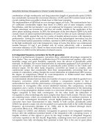
Fig. 5-1 Four kinds of network structures
In Fig. 5-1, (a) expresses the P parallel decoupling and compensating network (PPDCN), (b)
is the P serial decoupling and compensating network (VPDCN), (c) describes the V Parallel
Decoupling and Compensation Network (VPDCN),(d) is the V Serial Decoupling and
Compensation Network (VSDCN). In figures, Y
i
are the outputs of sensor, and L
i
are the
outputs of decoupling and compensating network.
5.2 Designs of dynamic decoupling and compensating networks
1. Design of PSDCN
The design procedure of PSDCN includes two steps. At first the decoupling part is
designed, and then the compensating part is done. The design goal of decoupling part is to
make the elements of non-main diagonal line in the matrix which is product of sensor
transfer function matrix and decoupling matrix be zero. The design goal of compensating
part is to make the compensating matrix equal to inverse of product matrix obtained by
multiplying the sensor transfer function matrix and the decoupling matrix. For n-
dimensional sensor, the decoupling matrix
p
sd
D and compensating matrix
p
sc
D in PSDCN
respectively are given by equation (5.1).
12 1
21 2
12
1
1
1
n
n
psd
nn
DD
DD
D
DD
⎡
⎤
⎢
⎥
⎢
⎥
=
⎢
⎥
⎢
⎥
⎣
⎦
11
22
1 1
1 1
11
psc
nn
D
D
D
D
⎡
⎤
⎢
⎥
⎢
⎥
=
⎢
⎥
⎢
⎥
⎣
⎦
(5.1)
Sensors, Focus on Tactile, Force and Stress Sensors
176
To decouple completely, we must have
psd psc
GD D I
⋅
⋅= (5.2)
Therefore
11 12 22 1
21 11 22 2
*
111 2 22
1
nnn
nnn
psd psc
nn nn
DDD DD
DD D DD
DD G
G
DD D D D
⎡⎤
⎢⎥
⎢⎥
⋅= =
⎢⎥
⎢⎥
⎣⎦
(5.3)
Where,
G is the determinant matrix of sensor transfer function G, and
*
G
is the
companion matrix of G.
To make the corresponding elements in equation (5.3) equal, the elements of
p
sd
D and
p
sc
D
are resolved as follows.
*
ii
ii
G
D
G
=
,
*
ji
ij
j
j
G
D
GD
=
⋅
( 1, 2, , ; 1,2, , ;injnij
=
=≠) (5.4)
2. Design of PPDCN
Designing PPDCN is used by a direct method of solving inverse matrix. Supposing PPDCN
to be the inverse matrix of sensor transfer function, the decoupling and compensating
matrix
p
pdc
D
is given by equation (5.5).
11 12 1
21 22 2
12
n
n
ppdc
nn nn
DD D
DD D
D
DD D
⎡
⎤
⎢
⎥
⎢
⎥
=
⎢
⎥
⎢
⎥
⎣
⎦
(5.5)
If
p
pdc
D is equal to the inverse matrix of sensor transfer function, the elements of
p
pdc
D can
be solved.
*
j
i
ij
G
D
G
=
, ( 1, 2, . , ; 1, 2, ;injn
=
= ) (5.6)
3. Design of VSDCN
The mathematical equations of VSDCN are given as follows.
1
,( 1,2, , )
n
ii ijj
j
ji
LY DLi n
=
≠
=+ =
∑
(5.7)
We can obtain
1
,( 1,2, , )
n
ii ijj
j
ji
YL DLi n
=
≠
=− =
∑
(5.8)
Study on Dynamic Characteristics of Six-axis Wrist Force/torque Sensor
177
Equation (5.7) can be written into a matrix form.
YLT
=
(5.9)
Here, Y and L are line vectors; T is a matrix described in equation (5.10).
12 1
21 2
12
1
1
1
n
n
nn
DD
DD
T
DD
−−
⎡
⎤
⎢
⎥
−−
⎢
⎥
=
⎢
⎥
⎢
⎥
−−
⎣
⎦
(5.10)
If T is the regular matrix, the decoupling matrix
vsd
D of VSDCN is given by
1
vsd
DT
−
= (5.11)
To reach decoupling and compensation completely, the following equation must be
satisfied.
vsd vsc
GD D I
⋅
⋅= (5.12)
Where
vsc
D is a compensating matrix.
Equation (5.12) yields
1
vsd vsc
DD G
−
⋅= (5.13)
Therefore
1
vsc
GDT
−
=
⋅
1
12
11 11 11
2
21
22 22 22
12
1
1
1
n
n
nn
nn nn nn
D
D
DD D
D
D
DD D
DD
DD D
⎡
⎤
−−
⎢
⎥
⎢
⎥
⎢
⎥
−−
⎢
⎥
=
⎢
⎥
⎢
⎥
⎢
⎥
⎢
⎥
−−
⎢
⎥
⎣
⎦
(5.14)
The model of VSDCN can be obtained from solving equation (5.14).
1
, , ( 1,2, , ; 1, 2, , ; )
ij
ii ij
ii ii
G
DD i nj nij
GG
=
=− = = ≠ (5.15)
4. Design of VPDCN
The mathematical equations of VPDCN are described by
1
( ), ( 1,2, , )
n
iiii ijj
j
ji
LDY DL i n
=
≠
=+ =
∑
(5.16)
From equation (5.16), we obtain
Sensors, Focus on Tactile, Force and Stress Sensors
178
1
,( 1,2, , )
n
i
iijj
j
ii
ji
L
YDLin
D
=
≠
=− =
∑
(5.17)
Equation (5.17) can be written in a matrix form
YLT
=
(5.18)
Where, Y and L are line vectors, and T is a
nn
×
matrix.
12 1
11
21 2
22
12
1
1
1
n
n
nn
nn
DD
D
DD
D
T
DD
D
⎡
⎤
−−
⎢
⎥
⎢
⎥
⎢
⎥
−−
⎢
⎥
=
⎢
⎥
⎢
⎥
⎢
⎥
⎢
⎥
−−
⎢
⎥
⎣
⎦
(5.19)
If T is the regular matrix, the
vpdc
D of VPDCN is
1
vpdc
DT
−
= (5.20)
In order to achieve decoupling and compensation, we have
vpdc
GD I
⋅
= (5.21)
Therefore
111
()
vpdc
GD T T
−−−
=
== (5.22)
The model of VPDCN can be solved from equation (5.22).
1
,
( 1,2, , ; 1,2, , ; )
ii ij ij
ii
DDG
G
injnij
==−
=
=≠
(5.23)
5. Designs of decoupling and compensating networks for non-minimum phase system
If the wrist force sensor is a non-minimum phase system, the above-mentioned method
which designs the dynamic decoupling and compensating networks will result in the result
to be unsteady. Therefore, before the dynamic decoupling and compensating networks are
designed, the dynamic compensating digital filters are designed for non-coupled paths. The
design of dynamic compensating digital filter can adopt the pole-zero configuration method
or system identification method [11, 12]. The result F of dynamic compensation for non-
coupled paths is
11 11
22 22
0 0
0 0
00
nn nn
fg
fg
F
f
g
⎡
⎤
⎢
⎥
⎢
⎥
=
⎢
⎥
⎢
⎥
⎣
⎦
(5.24)
Study on Dynamic Characteristics of Six-axis Wrist Force/torque Sensor
179
Where,
ii
g
(i=1,2,…,n) is the transfer function for the ith path of sensor,
ii
f
(i=1,2,…,n) is the
transfer function of dynamic compensating digital filter for the ith path of sensor.
In the design process of four kinds of dynamic decoupling and compensating networks,
supposed the product of sensor transfer function and the matrix of decoupling and
compensation to be equal to F, the corresponding decoupling and compensating network
are obtained. The deducing procedure is similar with the previous section. The models of
dynamic decoupling and compensating networks are as follows.
(1) PSDCN
*
ii ii ii
ii
f
GG
D
G
⋅
=
,
*
ji
ij
j
j
G
D
GD
=
⋅
( 1, 2, , ; 1, 2, ;injnij
=
=≠) (5.25)
(2) PPDCN
*
ii ii ii
ii
f
GG
D
G
⋅
=
,
*
j
iii ii
ij
GfG
D
G
=
1,2, , ; 1, 2, ;injnij
=
=≠
(5.26)
(3) VSDCN
, ,( 1,2, , ; 1, 2, , ; )
ij
ii ii ij
ii
G
DfD i nj nij
G
=
=− = = ≠ (5.27)
(4) VPDCN
, ,( 1,2, ,; 1,2, ,; )
ij
ii ii ij
ii ii
G
DfD i nj nij
fG
=
=− = = ≠
(5.28)
5.3 Determination of orders and parameters
A FLANN-based method is used to determine the orders and parameters of the dynamic
decoupling and compensating network. The system identification method can also been
used to do this work, but it sometimes makes the model orders too high or decoupling and
compensating results divergent because of modeling error. The FLANN method overcomes
these shortcomings.
The designs of decoupling parts in PSDCN, VSDCN and VPDCN have nothing to do with
the mix output signal of sensor, which includes non-coupled and coupled output signals.
Therefore using input and output signals of sensor under no coupled condition at first sets
up the models of decoupling parts. In design process of compensating part, the decoupling
model is used for decoupling coupled signal, and then the compensating parts are designed
in according with decoupled signal. Thus it can bring decoupling error in the design of
compensating parts, and correct decoupling error in the design of compensating parts.
Designing PSDCN and VSDCN can adopt the system identification method or the FLANN
method. Designing VPDCN only utilizes the FLANN method because it is a parallel
structure with internal feedback, and modeling error may result in divergent. Designing
PPDCN is complex, the models of compensating parts for non-coupled paths are set up at
first by using the input and output signals of sensor under no coupled condition. The
models of decoupling parts are trained by adjusting the difference between the
Sensors, Focus on Tactile, Force and Stress Sensors
180
compensating result of mix output signal and input signal. Thus we can bring the
compensating error in the design of decoupling part, and the compensating error is
corrected in the decoupling part.
Suppose the input signals of sensor are
()
i
X
k ; the output signals are ()
i
Yk. The
( 1), ,
i
Xk− ( ),( 1), ,( )
ii i
X
k r Yk Yk s
−
−− are obtained by the functional expansion
technique, which are used as the inputs of FLANN. The k expresses number of data,
1, ,kN= . The inputs are weighted and summed, and the output ()
i
Lk are yielded. The
difference between
()
i
Lkand ()
i
X
k is regarded as error ()
i
ek to adjust the weights ()
i
Wk
of FLANN. A schematic diagram of FLANN for determining parameters is shown in Fig.5-2.
An equation describing the neural algorithm can be written as
Yi (k)
Yi (k-1)
Yi (k-s)
Xi (k-1)
Xi (k-r)
-
Y i (k)
Xi (k)
∑
z
−1
z
−1
s
z
−
r
z
−
e
i(k)
L
i (k)
Fig. 5-2 Schematic of modeling by FLANN
11
() () ( ) ( 1) ( )
rs
ii i
pq
Lk wjXk p wq r Yk q
==
=
−+ ++ −
∑∑
(5.29)
The error is
() () ()
iii
ek X k Lk
=
− (5.30)
The weight update equations are given by
() () () ( )
ii ii
wp wp ekXk p
α
=
+⋅ −
(1)(1)()()
ii ii
wq r wq r ekYk q
α
+
+= +++⋅ − (5.31)
Where ()
i
Lk, ()
i
Yk,
()
i
ek
, ()
i
Wkstand for the desired output of the ith path, estimating
output, error and the pth or the qth linking weight in the kth step of the FLANN. The
α
denotes the learning constant which connects with the stability and the rate of convergence,
usually is selected about 0.1. In training process, initial values of weights are chosen about
0.1. After training for many times, when the average mean square error achieved a
minimum value, the weights of FLANN are the parameters of dynamic decoupling and
compensating network.
5.4 Dynamic decoupling and compensating results
1. Evaluating indexes
To evaluate the decoupling and compensating results, the indexes are adopted as the follows.
Study on Dynamic Characteristics of Six-axis Wrist Force/torque Sensor
181
(1) The variance is
2
()
1
ii
LX
N
σ
−
=
−
(5.32)
where
i
X
are the input signals of sensor,
i
L are corresponding decoupling and
compensating output signals, and N is total number of data.
(2) The relative error is
max
max
()
100%
ii
r
i
LX
e
X
−
=×
(5.33)
2. Results of simulation
In order to examine the decoupling and compensating methods, we carry out the
simulation. The results of simulation indicate that the VSDCN and VPDCN can achieve the
good effectiveness, but the results of PSDCN and PPDCN have error because these methods
use the low order model to substitute for the high order model.
3. Dynamic decoupling and compensating result of wrist force sensor
We decouple and compensate the dynamic output signals of wrist force sensor. The sensor is a
six-axis device, i.e. n=6, the decoupling parts of PSDCN and PPDCN are very complex with
high order. For examples, on the assumption that the model order of element in transfer
function matrix is 3, the order of decoupling and compensating model in PPDCN will high to
33, so it will result in the bad convergence and a big error because of simplification. In
generally, PSDCN and PPDCN can only be used for the dimensional number less than 3.
When the dimensional number larger than 3, VSDCN and VPDCN can only be used. The
models of these networks do not vary with the number of variables, so do not have the
problem of over-high order. For the wrist force sensor, we prefer VSDCN and VPDCN. In
brief, we only introduce the result of VSDCN. The decoupling and compensating results
between direction Z and direction X is shown in Fig.5-3 (a) and (b). The decoupling and
compensating results between direction Z and direction Y is shown in Fig.5-4 (a) and (b). In
the figures the orders of both decoupling and compensating models are 3, curve 1 expresses
the input signal of sensor, curve 2 expresses the decoupled and compensated result.
Fig. 5-3 (a) Decoupling and compensating result of direction Z
Sensors, Focus on Tactile, Force and Stress Sensors
182
Fig. 5-3 (b) Decoupling and compensating result of direction X
Fig. 5-4 (a) Decoupling and compensating result of direction Z
Fig. 5-4 (b) Decoupling and compensating result of direction Y
Study on Dynamic Characteristics of Six-axis Wrist Force/torque Sensor
183
Comparisons of the decoupling and compensating errors between direction Z and direction
X is seen in Table 5-1. Comparisons of the decoupling and compensating errors between
direction Z and direction Y are seen in Table 5-2. Analyzing Table 1 and Table 2, the results
of PSDCN are the worst and the results of VSDCN are the best.
Error indexes PSDCN PPDCN VSDCN VPDCN
σ
in direction Z
0.0880 0.0567 0.0543 0.0668
e
r
in direction Z 18.50% 19.35% 15.70% 14.25%
σ
in direction X
0.0717 0.0276 0.0270 0.0538
e
r
in direction X 19.71% 5.62% 5.53% 10.54%
Table 5-1 Comparisons of the decoupling and compensating errors between direction Z
and direction X
Error indexes PSDCN PPDCN VSDCN VPDCN
σ in direction Z
0.0731 0.0585 0.0586 0.0946
e
r
in direction Z 18.91% 20.59% 21.60% 25.10%
σ in direction Y
0.0960 0.0449 0.0301 0.0479
e
r
in direction Y 23.70% 13.37% 9.23% 13.10%
Table 5-2 Comparisons of the decoupling and compensating errors between direction Z and
direction Y
4. Conclusions
Four kinds of decoupling and compensating networks are presented in this section.
Analyzing from principle, compared with PSDCN and PPDCN, VSDCN and VPDCN are
more concise, they have definite physical meaning and can achieve full decoupling and
compensation. Judging from the construction, parallel networks are better than serial
networks because the decoupling and compensation are combined into one unit.
The decoupling and compensating error are caused mainly by the following reasons. (a)
There are modeling errors in four kinds of networks. (b) The simplification of molder result
in the errors in PSDCN and PPDCN.
The decoupling and compensating methods can also be applied to other multi-axis force
sensors.
6. Nonlinear dynamic characteristics
There is the non-linearity in the dynamic characteristics of sensors under some conditions.
In order to describe accurately the dynamic behavior of sensors some researchers studied
the nonlinear dynamic characteristics of sensors. Waldemar Minkina presented nonlinear
models that adequately describe the dynamic state of temperature sensor within the
temperature increase range [13,14]. Ping Wang et al. discussed the analysis of nonlinear
dynamic state of accelerometer transducers and its applications in the dynamic modeling
[15]. S. Beling et al. approximated the dynamic behavior of nonlinear gas sensors using the
feed-forward neural networks [16]. Haixia Zhang et al. studied the transient process of the
sensor probe, and developed a nonlinear model based on equivalent electrical circuit
techniques [17]. Ke-Jun Xu et al. studied the nonlinear dynamic characteristics of the wrist
Sensors, Focus on Tactile, Force and Stress Sensors
184
force sensor in the time and frequency domains [18,19]. These researches described the
nonlinear dynamic models of sensors only using one block. On the basis of these models the
nonlinear dynamic responses of sensors are compensated to improve the dynamic
performances of sensors. Antonio Pardo et al. built a nonlinear inverse dynamic system to
solve the non-linearity of gas sensing system [20]. Ke-Jun Xu et al. designed a dynamic
compensating system for the wrist force sensor using FLANN [21]. The nonlinear dynamic
compensations achieve good results under some certain conditions. Since the nonlinear
dynamic system is not satisfied with the homogeneity and superposition, the dynamic
compensations based on the above-mentioned nonlinear dynamic models are effective for
the certain response of sensors, but are not suitable for different form and different
amplitude responses of sensors.
6.1 Hammerstein model based modeling
Previous researchers present the nonlinear dynamic models of sensors only using a block,
which make it difficulty to compensate the nonlinear dynamic responses of sensors. The
models of sensors with the nonlinear dynamic characteristic may be divided into two
blocks, that is, a nonlinear static part and a linear dynamic one. The linear dynamic part is
first compensated and then the nonlinear static part is corrected. Thus the problems of
previous nonlinear dynamic compensations of sensors are solved. In this section a
Hammerstein model is adopted to describe the nonlinear dynamic models of sensors, and a
one-stage identification algorithm is proposed to simplify the calculation. On this basis a
two-step compensation method is present for the nonlinear dynamic responses of sensors.
1. Deduction of one-stage identification algorithm
The Hammerstein model is composed of a nonlinear static block
()N
⋅
followed by a linear
dynamic one
()ht , which is shown in Fig. 6-1 [22,23]. The ()ut and ()yt are the input and
output of the Hammerstein model respectively,
()t
ξ
is white noise, and ()
x
t stands for the
output of nonlinear static block.
Fig. 6-1 Hammerstein model
Assuming the nonlinear static block can be approximated by a polynomial, and can be
written as
1
() ( )
l
j
j
j
Ncut
=
⋅=
∑
(6.1)
And
[
]
() ()
x
tNut= (6.2)
The difference equation of the Hammerstein model is
Study on Dynamic Characteristics of Six-axis Wrist Force/torque Sensor
185
[
]
11
( )() ( ) () ()
A
qyk BqNuk k
ξ
−−
=+ (6.3)
Where
11
1
()1
n
n
A
qaqaq
−
−−
=+ + +" (6.4)
11
01
()
m
m
Bq b bq bq
−
−−
=+ ++" (6.5)
[]
1
() ()
l
j
j
j
Nuk cu k
=
=
∑
(6.6)
The transfer function of the linear dynamic block can be given as
1
1
01
1
1
()
1
m
m
n
n
bbz bz
Hz
az az
−−
−
−−
+++
=
+++
"
"
. (6.7)
Considering Equations (6.3), (6.4), (6.5) and (6.6), we can obtain
110
() ( ) ( ) ()
nlm
j
pvj
pjv
yk ayk p bcu k v k
ξ
===
=− − + − +
∑∑∑
(6.8)
Assuming
vj v j
wbc
=
0,1, , 1,vmjl
=
="". (6.9)
Then Equation (6.8) becomes
110
() ( ) ( ) ()
nlm
j
pvj
pjv
y
kaykp wukvk
ξ
===
=− − + − +
∑∑∑
(6.10)
Equation (6.10) can also be expressed as
() ()() ()yk k k k
θξ
Τ
=Φ + (6.11)
Where
10110
()[,,, ,, ,, ,, ]
nmlml
ka aw w w w
θ
Τ
= """"
()[( 1),, ( ),,(),,( ),,(),,( )]
ll
k yk ykn uk ukm uk ukm
Τ
Φ=−− −− − −"""""
Equation (6.11) is a parameter model describing the relation between the input and output.
The parameters of the model are obtained using the least square method (LSM) or the
FLANN [24].
Assuming that the gain of steady state of the linear dynamic unit is 1, that is
0
1
() 1
1
m
n
bb
H
aa
++
∞
==
+++
"
"
(6.12)
Thus the gain of steady state of the nonlinear dynamic system stems from the nonlinear
static block.
Sensors, Focus on Tactile, Force and Stress Sensors
186
When
1, 2, ,jl∀= " ,we can obtain the following equation from Equation (6.9).
0
0
()
m
vj m j
v
wb bc
=
=++
∑
"
0,1, , 1,vmjl
=
="". (6.13)
Then
00
01
1
mm
vj vj
vv
j
mn
ww
c
bbaa
==
==
+
++++
∑∑
""
(6.14)
Thus the coefficients of the nonlinear static block
1
,,
l
cc" are solved from
101
,,, ,,
nml
aaw w"" obtained by identification. On this basis we can yield
vj
v
j
w
b
c
=
0,1, , 1,vmjl
=
="". (6.15)
Now the coefficients of the linear dynamic unit are also obtained. Due to the inevitable
iterative error of the LSM or the FLANN,
v
b (0,1, )vm
=
" obtained from Equation (6.15)
may not satisfy Equation (6.12). However, the dynamic characteristics of a linear system,
such as what can be expressed as Equation (6.7), mainly depend on its poles instead of
zeros. While
v
b (0,1, )vm
=
" is the zero, and has little effect on the dynamic characteristics
of a system. Therefore Equation (6.7) can also be expressed as
1
1
12
()
1
n
A
Hz
az az
−
−−
=
+++
"
(6.16)
Where
1
1
n
i
i
A
a
=
=+
∑
(6.17)
This viewpoint may be proved as the following. Assuming
1
1.95974,a
=
−
2
0.98681,a =
0
0.00677,b =
12
0.01353, 0.00677bb
=
= ,and 2mn
=
= , the step responses of the system
are obtained from Equations (6.7) and (6.16) respectively, and are shown in Fig. 6-2. Two
response curves are identical. Even if we have not solved the parameters
v
b (0,1, )vm= " ,
the dynamic characteristics of the sensor can also be obtained. Therefore, using one-stage
identification method, we can obtain the coefficients of both the nonlinear static block and
the linear dynamic unit according to the inputs and outputs of the nonlinear dynamic
system.
2. Simulations of modeling
In order to examine the one-stage identification algorithm, the simulations are carried out.
The step signal and impulse signal are chosen as input signals of modeling because they are
usually applied to the experimental calibrations of sensors. Since a second-degree
polynomial is commonly used in describing the nonlinear static characteristics of sensors in
practice engineering, and a second-order linear dynamic unit is often admitted, we make
our simulations based on the second-degree nonlinear static model and the second-order
linear dynamic model. So let
2mn
=
= in Equations (6-4) and (6-5), and
2l
=
in Equation
Study on Dynamic Characteristics of Six-axis Wrist Force/torque Sensor
187
(6-6), then
1
a ,
2
a ,
0
b ,
1
b ,
1
c and
2
c are parameters that will be estimated. We should first
obtain
1
a ,
2
a ,
01 22
,,ww" through Equation (6-11).
Fig. 6-2 Comparison of two response curves: (1) step response of Equ.(6-7), and (2) step
response of Equ.(6-16).
Suppose a nonlinear static subsystem is
2
() () 0.5 ()
x
kuk uk=+ (6.18)
A linear dynamic unit is given by
( ) 1.95974 ( 1) 0.98681 ( 2)yk yk yk
=
−− −
0.00667 ( ) 0.01353 ( 1) 0.00667 ( 2)xk xk xk
+
+−+− (6.19)
A step input signal and a nonlinear dynamic response of the system are shown in Fig. 6-3.
According to the inputs and outputs of the system,
12 01 22
,, ,,aaw w" , parameters in
equation (6.11), are obtained using the LSM. Afterwards
01212
,,,,bbbcc can be easily
obtained through Equations (6.14) and (6.15). Thus a nonlinear dynamic model is set up
using the one-stage identification algorithm. The response of this model is compared with
that of the supposed system which is shown in Fig. 6-4. The supposed and identified
parameters are listed in Table 6-1.
Fig. 6-3 Step input and supposed nonlinear dynamic response: (1) step input, and (2)
nonlinear dynamic response .
Sensors, Focus on Tactile, Force and Stress Sensors
188
Fig. 6-4 Comparison of identification result and supposed response: (1) supposed response,
and (2) identification result.
Parameter a
1
a
2
b
0
b
1
b
2
c
1
c
2
Supposed -1.95974 0.98681 0.00677 0.01353 0.00677 1.00 0.50
Identified -1.95971 0.98679 0.00437 0.01323 0.00948 0.99663 0.50188
Table 6-1 Comparison between supposed and identified parameters
The simulation results of the impulse signal are shown in Fig. 6-5 and Fig. 6-6. The supposed
and identified parameters are listed in Table 6-2.
Fig. 6-5 Impulse input and nonlinear dynamic response: (1) impulse input, and (2) nonlinear
dynamic response.
Fig. 6-6 Comparison of identification result and supposed response: (1) supposed response,
and (2) identification result.
Study on Dynamic Characteristics of Six-axis Wrist Force/torque Sensor
189
Parameter
1
a
2
a
0
b
1
b
2
b
1
c
2
c
Supposed -1.95974 0.98681 0.00677 0.01353 0.00677 1.00 0.50
Identified -1.95974 0.98681 0.00676 0.01350 0.00675 0.99995 0.50014
Table 6-2 Comparison between parameters supposed and identified
All above simulation results show that the performance and convergence of the algorithm
presented in this section are good.
3. Modeling of wrist force sensor
The impulse response method is easily done and works well in the dynamic calibrations of
sensors. So we adopt this method to make the dynamic calibration experiments of the wrist
force sensor. In the calibration, a wrist force sensor is mounted on a testing platform. If no
load is placed on the wrist sensor in the dynamic calibration, we call it no-load-calibration
(NLC); while when there is some load laid on the wrist force sensor, we call it having-load-
calibration (HLC). An impulse force is applied to the wrist force sensor with a hammer, that
is, the hammer strikes vertically on the sensor directly in the NLC or on the load placed on
the sensor in the HLC in a very short interval. In the head of the hammer, a piezoelectric
sensor is installed to transform the impulse force into the electric charge signal. This signal is
amplified by a charge amplifier and sent to a computer based data acquisition system. The
wrist force sensor outputs six channel signals, of which three channels express force
components of x, y, and z directions, and three channels express moment components of x,
y, and z directions. These six channel signals of the wrist force sensor are also collected by
the data acquisition system.
In the NLC, the zero point of work of the wrist force sensor is located in the middle part of
the linear working range, so the dynamic response of the sensor is linear. But in HLC, the
position of the zero point of work is moved from the linear working range to the nonlinear
working range because of the applied load. Therefore the effect of the nonlinear factor
becomes serious. The dynamic response of the sensor in HLC is nonlinear. The impulse
response of NLC is shown in Fig. 6-7, and that of HLC in Fig. 6-8.
In order to demonstrate the superiority, in the modeling of sensors, of the algorithm presented
in this section, the following work is done. First assume the models of sensors in NLC and
HLC are linear, we carry out linear modeling (LM) using the LMS. Secondly we regard the
models of sensors as nonlinear ones, and identify them with the algorithm presented in this
section, which is nonlinear modeling (NLM). Finally we compare these identification results.
Fig. 6-9 and Fig. 6-10 show their difference in terms of curves, and Table 6-3 and Table 6-4 in
terms of parameters. The sum of square error
2
e
∑
of each identified curve to the real
impulse response is used to evaluate the accuracy of model, which is shown in Table 6-3 and
Table 6-4. The smaller is the value of
2
e
∑
; the better is the identification result.
The two curves in Fig. 6-9 are almost overlapped to each other, and the identified
parameters with the algorithm presented in this section contain a small coefficient value
2
c .
It shows that the nonlinear factor of the impulse response in NLC is not very serious or
there lies a quite weak non-linearity. But in Fig. 6-10, two curves have a little difference, and
the value of coefficient
2
c is not a very small one. The nonlinear factor should be considered
under this circumstance. Judging from the values of
2
e
∑
in Table 6-3 and 6-4, we come to
the conclusion that the nonlinear modeling method presented in this section is better than
that of the linear modeling method in describing the model of the wrist force sensor.
Sensors, Focus on Tactile, Force and Stress Sensors
190
Fig. 6-7 Impulse response in NLC: (1) impulse input, and (2) dynamic response of the
sensor.
Fig. 6-8 Impulse response in HLC: (1) impulse input, and (2) dynamic response of the
sensor.
Fig. 6-9 Comparison of modeling in NLC with two kinds of methods: (1) modeling with LM,
and (2) modeling with NLM.
Study on Dynamic Characteristics of Six-axis Wrist Force/torque Sensor
191
Fig. 6-10 Comparison of modeling in HLC with two kinds of methods: (1) modeling with
LM, and (2) modeling with NLM.
Parameter
1
a
2
a
1
c
2
c
2
e
∑
LM -1.97785 0.99095 15.97152
NLM -1.97818 0.99138 0.89319 0.05800 12.08818
Table 6-3 Comparison between linear modeling and nonlinear modeling in NLC
Parameter
1
a
2
a
1
c
2
c
2
e
∑
LM -1.96237 0.96528 3.45087
NLM -1.96144 0.96438 1.48733 -0.19036 3.38959
Table 6-4 Comparison between linear modeling and nonlinear modeling in HLC
4. Discussions
The one-stage identification algorithm has advantages as follows: (1) One-stage
identification simplifies the algorithm; (2) It depends only on the data of input and output of
the system, not needing to introduce the auxiliary variables that could not be measured in
practice; (3) It only needs dynamic calibration experimental data of systems, not needing to
do static calibration experiments. On the basis of identification, the nonlinear dynamic
compensation is easily completed.
6.2 Hammerstein model based correction
With the increasing higher requirement of the dynamic measurement, it is more and more
important to improve the dynamic performances of sensors. We brought forward a
nonlinear compensation method for the Hammerstein model. The Hammerstein model is
composed of two parts, one linear dynamic unit and one nonlinear static subsystem,
therefore the compensation includes two steps accordingly: The first step is linear dynamic
compensation and the second one is nonlinear static correction. Thus we call it two-step
compensation. Fig. 6-11 shows a block diagram of this method. The linear dynamic
compensation unit is
'( )ht, and the inverse unit of the nonlinear static subsystem ()N ⋅ is
1
()N
−
⋅ . The ultimate compensated output is '( )ut.
Sensors, Focus on Tactile, Force and Stress Sensors
192
)(tx )(ty)(tu )(' tu)(' tx
)(
⋅
N )(th )(' th
)(
1
⋅
−
N
Fig. 6-11 A block diagram of two-step compensation
A linear dynamic compensation unit
'( )ht is designed using the pole-zero configuration
method or system identification method [24]. Through the linear dynamic compensation, we
get '( )
x
t . A nonlinear static correction unit
1
()N
−
⋅
should be designed. The nonlinear static
subsystem can be expressed by a second-degree polynomial.
2
12
[()] () () ()Nuk xk cuk cu k== + (6-20)
Its inverse system is assumed as
12
01 2
ˆˆ ˆ ˆ
[()] () () ()Nxk uk d dxk dxk
−
==+ + (6-21)
Where
ˆ
()uk
and
ˆ
()
x
k are the predictive data,
2
12
ˆˆˆ
() () ()
x
kcukcuk=+ . Though
12
,cc have
been obtained,
1
()N
−
⋅
is still difficult to be solved from Equation (6-16). We adopt the
FLANN to get the parameters
012
,,ddd of
1
()N
−
⋅
as the artificial neural network has the
excellent approximation property. A schematic diagram of the FLANN for training
parameters is shown in Fig. 6-12.
Fig. 6-12 A training schematic diagram of the FLANN
1. Simulations of nonlinear dynamic compensation
Using the compensation method stated above, the simulation results of the step response
and impulse response are shown in Fig. 6-13 ~ Fig. 6-16. Fig. 6-13 and Fig. 6-15 show the
results of the first step, that is linear dynamic compensation, compared with the output
signal of sensors. Fig. 6-14 and Fig. 6-16 show the results of the second step, that is nonlinear
static correction, compared with the input signal of sensors. It can be seen that the method of
nonlinear dynamic compensation is effective.
Study on Dynamic Characteristics of Six-axis Wrist Force/torque Sensor
193
Fig. 6-13 The first step of compensation: (1) nonlinear dynamic response, and (2) dynamic
compensation of the first step.
Fig. 6-14 The second step of compensation compared with the input signal (1) step input, (2)
nonlinear static correction of the second step.
Fig. 6-15 The first step of compensation (1) nonlinear dynamic response, (2) dynamic
compensation of the first step.
Sensors, Focus on Tactile, Force and Stress Sensors
194
Fig. 6-16 The second step of compensation compared with the input signal (1) impulse
input, (2) nonlinear static correction of the second step.
2. Compensation of the impulse response of wrist force sensor
The impulse responses of the wrist force sensors in NLC and HLC are compensated using
the two-step nonlinear dynamic compensation method. Fig. 6-17 shows the result of the
nonlinear dynamic compensation for NLC, and Fig. 6-18 shows the result of the linear
dynamic compensation using the linear compensation method. Comparing the two results,
we find that the compensation result in Fig. 6-17 is not better than that in Fig. 6-18, because
the nonlinear dynamic factor is a weak one, as we have analyzed in above section.
Fig. 6-17 Compensation result of NLC compared with the input signal (1) impulse input, (2)
nonlinear dynamic compensation result
Fig. 6-18 Compensation result of NLC using linear approach compared with the input signal
(1) impulse input, (2) compensation result
Study on Dynamic Characteristics of Six-axis Wrist Force/torque Sensor
195
Fig. 6-19 shows the result of the nonlinear dynamic compensation for HLC, and Fig. 20
shows the result of the linear dynamic compensation for HLC. The nonlinear compensation
method is better than the linear one in HLC.
Fig. 6-19 Compensation result of HLC compared with input signal (1) impulse input, (2)
nonlinear static correction of the second step
Fig. 6-20 Compensation result of HLC using linear approach compared with the input signal
(1) impulse input, (2) compensation result
6.3 Wiener model based modeling and correction
A kind of nonlinear dynamic compensation method is proposed based on the Wiener
model. Sensors with the nonlinear dynamic characteristics are describing as the Wiener
model that is the cascade connection of a linear dynamic subsystem followed by a nonlinear
static part. The nonlinear static characteristic of sensors is first corrected, and then the linear
dynamic response is compensated. A DSP-based nonlinear dynamic compensating system
and a sensor simulator are developed, and the experiments are carried out to demonstrate
the effect of the nonlinear dynamic compensation method.
1. Principle of nonlinear dynamic compensation
Some sensors with the nonlinear dynamic characteristics can be divided into a linear
dynamic subsystem and a nonlinear static part, which is shown in Fig. 6-21. They can be
described by the differential equation as the following.