Báo cáo hóa học: "Fabrication of Uniform Au–Carbon Nanofiber by Two-Step Low Temperature Decomposition" docx
Bạn đang xem bản rút gọn của tài liệu. Xem và tải ngay bản đầy đủ của tài liệu tại đây (369.56 KB, 5 trang )
NANO EXPRESS
Fabrication of Uniform Au–Carbon Nanofiber by Two-Step
Low Temperature Decomposition
Myeongsoon Lee Æ Seong-Cheol Hong Æ
Don Kim
Received: 1 April 2009 / Accepted: 5 May 2009 /Published online: 22 May 2009
Ó to the authors 2009
Abstract This paper presents a facile and efficient way to
prepare carbon nanofibers ornamented with Au nanoparti-
cles (Au/CNFs). Gold nanoparticles were first deposited in
the channels of an anodized aluminum oxide (AAO)
membrane by thermal decomposition of HAuCl
4
and then
carbon nanofibers were produced in the same channels
loaded with the Au nanoparticles by decomposition of
sucrose at 230 °C. An electron microscopy study revealed
that the carbon nanofibers, *10 nm thick and 6 lm long,
were decorated with Au nanoparticles with a diameter of
10 nm. This synthetic route can produce uniform Au
nanoparticles on CNF surfaces without using any addi-
tional chemicals to modify the AAO channels or the CNF
surfaces.
Keywords Au Á Carbon Á Nanoparticles Á Nanofibers Á
AAO
Introduction
Carbon nanostructures have attracted extensive attentions
due to their unique physicochemical properties and prom-
ising applications in nanodevices [1, 2]. One of the major
challenges for nanodevice fabrication is how to immobilize
the functional nanostructures on electrically conducting
electrodes. Amma et al. [3] demonstrated that extremely
hydrophilic carbon nanotubes (CNTs) could be immobilized
on a hydrophilic Au surface by means of electrostatic
interaction. However, this technique requires harsh chemical
reactions (e.g. azo-coupling) to modify the CNT surface with
a hydrophilic group (e.g., –SO
3
Na). The harsh reaction
conditions and the bonded chemical groups may cause some
changes of the intrinsic nature of the carbon nanotubes.
Therefore, an alternative immobilization method under
relatively mild reaction conditions is desirable to assemble
the carbon nanodevices without sacrificing the unique
properties of the carbon nanotube. One of the most prom-
ising immobilization methods would be to attach Au
nanoparticles on the carbon nanostructure as anchoring
posts. The Au nanoparticles offer the great potential in
nanodevice assembly because the Au surface can be easily
modified to interact with a substrate through a mild
chemical treatment [4, 5]. There are some known methods
to attach Au nanoparticles to carbon nanostructures [6–8].
For example, Au nanoparticles can be attached to CNTs by
chemical reductions of HAuCl
4
either in a solution of CNT
stabilized by surfactant [6] or surface-modified CNTs [7].
However, the intrinsic surface properties of CNTs could
not be sustained due to the surface modification chemicals
[6, 7]. The Au/CNTs can also be prepared by a direct
pyrolysis of HAuCl
4
/acetone mixture in a template [8].
This may be the simplest method to prepare the Au-
decorated 1D carbon nanostructures [1, 2, 9–14]. But this
method could be applied only to get large the diameter
([ *180 nm) of carbon tubes [8].
We investigated a facile route to prepare the Au nano-
particle loaded carbon nanostructures by a two-step ther-
mal decomposition method. This method consists of the
thermal decomposition of HAuCl
4
followed by the car-
bonization of sucrose in anodized aluminum oxide (AAO)
channel, 80 nm in diameter. In the previous paper, we have
shown that monodisperse Au-nanoparticles with a diameter
of *10 nm can be produced by thermal decomposition of
HAuCl
4
solution infiltrated in the AAO channel [15].
M. Lee Á S C. Hong Á D. Kim (&)
Department of Chemistry, Pukyong National University, 599-1
Daeyon 3 dong, Namgu, Busan 608-737, Korea
e-mail:
123
Nanoscale Res Lett (2009) 4:932–936
DOI 10.1007/s11671-009-9341-7
This synthesis route produces carbon nanofibers orna-
mented with uniform sizes Au nanoparticles. Since the Au
nanoparticles are synthesized first and the sucrose car-
bonization is carried out at the same temperature used for
the Au nanoparticle synthesis, the property of Au nano-
particles will not be disrupted during the carbon nanofiber
growth. Once the carbon fibers are produced, the Au/car-
bon nanostructure can be released from the AAO channel
under mild chemical etching conditions. Therefore, the
intrinsic properties of the complexed nanostructures will
not be altered greatly.
Experimental Details
The AAO membrane was prepared by the Masuda process
[16] and the diameter of AAO channels was controlled to
ca. 80 nm. The uniform Au nanoparticles (*10 nm) were
embedded inside the AAO channels by a thermal decom-
position of HAuCl
4
at 230 °C. The detailed procedure was
described elsewhere [15]. Then the AAO membranes loa-
ded with Au nanoparticles (Au–AAO) were soaked in a
sucrose (Aldrich ACS grade) aqueous solution for 24 h
followed by heating to 230 °C for 30 min under the
nitrogen (99.9%) flow to carbonize the sucrose. The heat-
ing ramping rate was 4 °C/min. The AAO frame was
removed in an etch solution (6% H
2
CrO
4
:1.8% H
3
PO
4
=
1:1 in volume) and rinsed several times with deionized
water. The carbon nanostructures decorated with Au
nanoparticles (Au/C) were retrieved from the solution. For
comparison, bare carbon nanostructures without Au nano-
particles were synthesized via the same carbonization
procedure inside the pristine AAO channels. The samples
were characterized with field-emission scanning electron
microscopy (FE-SEM, JEOL JSM6700-F), transmission
electron microscopy, energy dispersive X-ray spectroscopy
and selected area electron diffraction (TEM/HRTEM/EDX/
SAED, JEOL JEM-2010), powder X-ray diffractometry
(XRD, Philips X’Pert MPD system, Cu Ka radiation),
and X-ray photoelectron spectroscopy (XPS, VG-Multilab
2000).
Results and Discussion
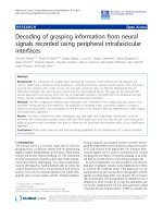
Figure 1a and b shows XRD patterns of Au/C embedded in
AAO membrane (Au/C–AAO) and carbon embedded in
AAO membrane (C–AAO), respectively. The embedded
carbon phase is amorphous. There are no recognizably
specific reflections of crystalline carbon in XRD patterns.
The diffraction peaks of Au in the XRD pattern of Au/
C–AAO are identical to those of Au–AAO [15]. This
indicates that the crystal structure of the Au nanoparticles
does not change during the carbonization. The insets in
Fig. 1 are the optical images of bare AAO, Au–AAO, and
Au/C–AAO. After embedding the Au nanoparticles in bare
AAO, the transparent AAO membrane exhibited a dark red
wine color (k
max
= 528 nm), which is characteristic color
of the colloidal Au nanoparticles. The color change is
indicative of the conversion from HAuCl
4
to Au nanopar-
ticles. The embedded Au nanoparticles (ca. 10 nm in
diameter) partially coalesced with each other to form con-
ducting Au nanotubes/nanoparticles on the walls of AAO
channels [15]. After the carbonization of the infiltrated
sucrose at 230 °C under the nitrogen gas flow, the wine
color of the membrane turned to black. This carbonization
temperature, which is higher than the decomposition tem-
perature of sucrose (*185 °C) [17] and the same as the
decomposition temperature of HAuCl
4
in AAO to form Au
nanotubes, [15] would not change the properties of the Au
nanoparticles pre-embedded in AAO channels.
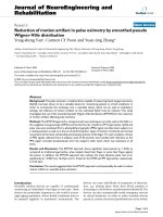
The enriched carbon in Au/C–AAO was confirmed by
the XPS analysis. Compared with the spectrum for the Au–
AAO sample, Fig. 2a, the intensity of the characteristic
binding energies of C 1s peak (285.0 eV) was remarkably
enhanced after the carbonization as shown in Fig. 2b. The
binding energies of Al 2p (75.5 eV), O 1s (532 eV), and
Au 4f (88.5 and 85 eV) in the XPS spectrum of Au/
C–AAO corresponded well with those of Au–AAO in other
reports [7, 18–20].
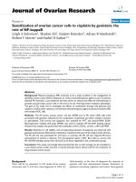
Figure 3a is a TEM image of carbon nanotube bundles,
which were prepared by the carbonization of the infiltrated
sucrose in the pristine AAO membrane. The diameter of
the nanotubes is the same as that of AAO channels, 80 nm.
EDX analysis (not shown here) confirmed that the tube
Fig. 1 XRD patterns of (a) carbonized sucrose in Au nanoparticles
embedded AAO (Au/C–AAO) and (b) carbonized sucrose in anodized
aluminum oxide(C–AAO) template. Insets are optical images of bare
AAO, Au–AAO, and Au/C–AAO membrane (from left to right)
Nanoscale Res Lett (2009) 4:932–936 933
123
consists of carbon. Figure 3b is a TEM image of the free-
standing Au/CNFs. The dark spots in the image are Au
nanoparticles. The inset of Fig. 3b is the SEM image of
Au/CNTs in the AAO template. According to EDX
analysis (not shown here), the chemical compositions of
the imaged area co-insist with Au and carbon in addition
to the aluminum oxide. Although some reports claimed that
the formation of carbon nanostructures via the carboniza-
tion of sucrose inside nano-templates is possible only with
aid of sulfuric acid [11–14] or linker chemicals, [9] the
present method shows that the carbonization of sucrose in
the AAO channel can be carried out to form carbon
nanostructures without additional chemicals.
Although the thermal decomposition process of sucrose
includes complicated multiple steps, [17] it can be sim-
plified as C
12
(H
2
O)
11
? 12C(s) ? 11H
2
O(g). If this reac-
tion occurs in the AAO channels, the water vapor will be
evolved and form bubbles. The bubble formed inside a
channel, when escapes, pushes outward the sucrose phase
at the outer region of the channel. At the same time, due to
the strong adhesion between the aluminol groups of AAO
and the hydroxyl groups of sucrose, [21] a thin layer of
sucrose might remain on the wall of AAO channel. Finally,
the decomposition of the coated sucrose on as-prepared
AAO channel will result in the nanotubes as shown in
Fig. 3.
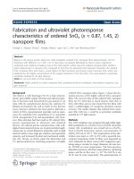
Initially, it was expected that carbon tubes, 80 nm in
diameter, coated with Au nanoparticles could be prepared
through the carbonization of sucrose inside the AAO pre-
loaded with Au nanoparticles (Au–AAO) with the same
procedure as discussed above. Instead, however, Au dec-
orated carbon nanofibers (Au/CNFs) were obtained as
shown in Fig. 4a. A higher resolution image (Fig. 4b)
shows that the thickness of the CNFs approaches around
10 nm. The dark spots in the image are crystalline Au
nanoparticles as shown in the SAED pattern of Au
nanoparticle (inset of Fig. 4a). The circled area in Fig. 4c
shows a bundle of cross-linked Au/CNFs and the distance
between the dark lines is 80 nm, which corresponds to the
diameter of the AAO channels. From these images, it is
noteworthy that the width of Au/CNFs corresponds to the
diameter of Au nanoparticles and the length of the bridge
Fig. 2 XPS spectra of a Au embedded AAO and b carbonized
sucrose in Au embedded AAO. Peaks were calibrated against the
binding energy of C 1s (285.0 eV)
Fig. 3 a TEM image of carbon
nanotubes prepared in anodized
aluminum oxide (AAO)
template and b TEM image of
free standing carbon nanotubes
ornamented with Au
nanoparticles. The inset is SEM
image of carbon nanotubes in
Au embedded AAO (Au/
C–AAO) template. The
Au/C–AAO was crashed to
expose the edge
934 Nanoscale Res Lett (2009) 4:932–936
123
between two dark lines in the cross-linked Au/CNFs cor-
responds to the diameter of AAO channel, 80 nm. Fig-
ure 4d is the distribution plot of 185 Au nanoparticles
appeared in Fig. 4b. The mean diameter of Au nanoparticle
was 9.2 nm.
The formation of long narrow nanofibers (Au/CNFs)
shown in Fig. 4a, may be not explained by the above
simple extrusion model. It was confirmed that the pre-
loaded Au nanoparticles coat all over the AAO channel
[15]. Therefore, if all Au nanoparticles take part in the
formation of Au/CNF, the carbon fibers would be fully
coated. But, the TEM image of Au/CNFs shows that not so
much Au nanoparticles are attached. This suggests that a
great part of Au nanoparticles are removed from the inside
of the AAO channels during the decomposition process.
The fact that the CNFs have the same diameter of the Au
nanoparticles and the distance of the bridge in the cross-
linked CNFs is the same as the diameter of AAO channel
suggests that the fibers are the splits of the tubular shape of
carbon. We could not get in situ information of the
Fig. 4 TEM images of a Au
ornamented carbon nanofibers,
b magnified image of the circled
section on a, and c other area of
the same TEM grid. d The
histograms of particle size
distribution of b. The inset in a
is a SAED pattern of an Au
nanoparticle
Fig. 5 Schematic diagram of
the two-step preparation
method. The preloaded Au
nanoparticles act like knife
blade during decomposition of
sucrose and result carbon
nanofibers. TEM image is low
magnified free standing Au/C
nanofibers
Nanoscale Res Lett (2009) 4:932–936 935
123
extrusion activity in the channel during the decomposition.
However, it could be speculated that the Au nanoparticles
(*10 nm in diameter) could act as blades during the
thermal extrusion, as schematically shown in Fig. 5. In this
case, the Au nanoparticles would be aligned at the interface
of liquefied (partially decomposed) sucrose and water
vapor bubble, which generated during the thermal
decomposition. Then the distance between the Au nano-
particle’s center (i.e., distance between the gold blades)
become *10 nm. The aligned Au particles could split the
sucrose layer, which is coated on the wall of AAO channel
as discussed in previous section, when the water vapor
bubble is expanded by continuing decomposition. This will
result in the evenly sectioned (10 9 10 nm) carbon
nanofibers up to several micrometers long with Au nano-
particles as ornament, as shown in Fig. 5.
In conclusion, we demonstrated a facile route for the
synthesis of carbon nanotubes and dimension-confined
(10 9 10 nm) nanofibers decorated with size-defined
(10 nm) Au nanoparticles by the carbonization of sucrose
in the AAO channels which were coated with Au nano-
particles without any chemical additives or further chem-
ical reactions. The attached Au nanoparticles could be used
as good anchoring posts to assemble carbon nanostructures
on proper substrates.
Acknowledgments This work was supported by Pukyong National
University Research Abroad Fund in 2007(PS-2007-010). D.K. is
grateful to Prof. S.H. Kim for his stay and research at Penn State.
References
1. Q. Shi, H. Liang, D. Feng, J. Wang, G.D. Stucky, J. Am. Chem.
Soc. 130, 5034 (2008). doi:10.1021/ja800376t
2. C. Liang, Z. Li, S. Dai, Angew Chem. Int. Ed. 47, 3696 (2008).
doi:10.1002/anie.200702046
3. A. Amma, B. Razavi, S.K. St. Angelo, T.S. Mayer, T.E. Mallouk,
Adv. Funct. Mater. 13, 365 (2003). doi:10.1002/adfm.200304232
4. M.S. Lee, S.C. Hong, D. Kim, Jpn. J. Appl. Phys. 43, 8347
(2004). doi:10.1143/JJAP.43.8347
5. M.S. Lee, S.C. Hong, D. Kim, Appl. Surf. Sci. 252, 5019 (2006).
doi:10.1016/j.apsusc.2005.07.019
6. D.S. Kim, T. Lee, K.E. Gerkeler, Angew Chem. Ind. Ed. 45, 104
(2005)
7. X. Hu, T. Wang, X. Qu, S. Dong, J. Phys. Chem. B 110, 853
(2006). doi:10.1021/jp055834o
8. P. Goring, E. Pippel, H. Hofmeister, R.B. Wehrspohn, M.
Steinhart, U. Gosele, Nano Lett. 4, 1121 (2004). doi:10.1021/
nl049542v
9. A.T. Rodriguez, M. Chen, Z. Chen, C.J. Brinker, H. Fan, J. Am.
Chem. Soc. 128, 9276 (2006). doi:10.1021/ja061380c
10. C.T. Hsieh, J.M. Chen, R.R. Kuo, Y.H. Huang, Appl. Phys. Lett.
84, 1186 (2004). doi:10.1063/1.1646746
11. S.H. Joo, S.J. Choi, I.W. Oh, J.H. Kwak, Z. Liu, O. Terasaki,
Nature 412, 169 (2001). doi:10.1038/35084046
12. S.J. Han, M.S. Kim, T.H. Hyeon, Carbon 41, 1525 (2003). doi:
10.1016/S0008-6223(03)00072-1
13. J.W. Lee, J.Y. Kim, T.H. Hyeon, Adv. Mater. 18, 2073 (2006).
doi:10.1002/adma.200501576
14. J. Siochi, US Patent US2006013756
15. M.S. Lee, S.C. Hong, D. Kim, Appl. Phys. Lett. 89, 043120
(2006). doi:10.1063/1.2221883
16. H. Masuda, K. Fukuda, Science 268, 1466 (1995). doi:
10.1126/science.268.5216.1466
17. I. Simkovic, I. Surina, M. Vrican, J. Anal. Appl. Pyrol. 70, 493
(2003). doi:10.1016/S0165-2370(03)00007-X
18. T. Qiu, X.L. Wu, G.G. Siu, P.K. Chu, Appl. Phys. Lett. 87,
223115 (2005). doi:10.1063/1.2138360
19. T.P. Nguyen, J. Ip, P. Le Rendu, A. Lahmar, Surf. Coat. Technol.
141, 108 (2001). doi:10.1016/S0257-8972(01)01165-3
20. A. Szytula, D. Fus, B. Penc, A. Jezierski, Alloy. J. Compd. 317,
340 (2001)
21. K. Singh, Appl. Surf. Sci. 221, 308 (2004). doi:10.1016/S0169-
4332(03)00950-4
936 Nanoscale Res Lett (2009) 4:932–936
123