báo cáo hóa học:" Research Article An Efficient Segmental Bus-Invert Coding Method for Instruction Memory Data Bus Switching Reduction" doc
Bạn đang xem bản rút gọn của tài liệu. Xem và tải ngay bản đầy đủ của tài liệu tại đây (709.84 KB, 10 trang )
Hindawi Publishing Corporation
EURASIP Journal on Embedded Systems
Volume 2009, Article ID 973976, 10 pages
doi:10.1155/2009/973976
Research Article
An Efficient Segmental Bus-Invert Coding Method for
Instruction Memory Data Bus Switching Reduction
Ji Gu and Hui Guo
School of Computer Science and Engineering, The University of New South Wales, Sydney 2052, Australia
Correspondence should be addressed to Ji Gu,
Received 20 January 2009; Accepted 3 July 2009
Recommended by Antonio Nunez
This paper presents a bus coding methodology for the instruction memory data bus switching reduction. Compared to the existing
state-of-the-art multiway partial bus-invert (MPBI) coding which relies on data bit correlation, our approach is very effective in
reducing the switching activity of the instruction data buses, since little bit correlation can be observed in the instruction data.
Our experiments demonstrate that the proposed encoding can reduce up to 42% of switching activity, with an average of 30%
reduction, while MPBI achieves just 17.6% reduction in switching activity.
Copyright © 2009 J. Gu and H. Guo. This is an open access article distributed under the Creative Commons Attribution License,
which permits unrestricted use, distribution, and reproduction in any medium, provided the original work is properly cited.
1. Introduction
Designs of portable consumer electronic devices such as
mobile phones, PDAs, video games, and other embedded
systems are increasingly demanding low power consump-
tion to maximize the battery life, reduce weight, and
improve reliability. These types of power sensitive devices
are usually equipped with microprocessors as the processing
elements and memories as the storage units. With current
CMOS technology, a large portion of power consumption
is consumed in the form of dynamic power, which in
turn is determined by the bit switching and the switched
load capacitance. (Leakage power becomes unneglectable in
nanoscaled devices. However, leakage power optimization
achieves better in low-leakage component design at the phys-
ical level, for which paper [1] can be a good reference. In this
paper we mainly focus on dynamic power reduction at the
system level of the off-chip bus.) Since the microprocessor
fetches instructions over the memory bus every clock cycle
and bus lines to memory are often much longer than buses
within the processor, the power consumed by the bus due to
instruction fetch is significant.
So far, research for the instruction data bus switching
reduction has generally concentrated on code compression.
The compressed code causes less memory access, thus
reducing the bus activity. Compression requires compli-
cated compression/decompression units, which reside in
the critical path and can considerably affect the overall
system performance. In this paper, we investigate a different
approach—bus encoding.
Most of existing bus encoding schemes are effective
for address or data memory buses and mainly utilize
correlations of transferred data. For example, T0 [2]and
Gray encodings [3] use the temporal correlation of data on
address buses, while the bus-invert encoding [4] exploits
the spatial t ransition correlation among the data bits. We
investigated the data on the instruction data buses and
found that the bit switching behavior of the instruction
data bus is different from those of the other types of buses.
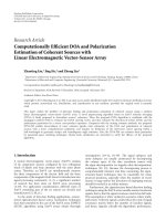
Figure 1 shows an experimental result of the bit transition
probability for three different memory buses: instruction
memory address bus (imab) instruction memory data bus
(imdb) and data memory data bus (dmdb) (all over the 32-bit
bus space of the SimpleScalar ISA [5]).
As can be seen from Figure 1, switching activit y on the
instruction address bus concentrates on the low section
of bits, largely due to the sequential access of instruction
memory. For the data memory data bus, the switching
activity spreads over all bus bits with almost 50% switching
probability. But for the instruction data bus, the switching
2 EURASIP Journal on Embedded Systems
1
0
0.2
0.4
0.6
Bit switching probability
0.8
1
3 5 7 9 11 13 15
Bus bit
Bus bit switching pattern
17 19 21 23 25 27 29 31
imab
imdb
dmdb
Figure 1: Bit switching probability of different buses.
CPU
IM DM
Address Address
Data Data
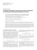
Figure 2: System architecture.
probability is not evenly distributed. Some bits show very low
switching activity. Therefore, most of existing encodings for
address buses and data memory data buses do not suit for
encoding of the instruction data buses.
Since there are some bits on the instruction buses with
high switching frequency, it is possible to use segmental
bus-invert encoding—a set of bus segments are selected and
to each segment the traditional bus-invert (BI) encoding
is performed such that the bus switching activity can be
reduced.
In this paper, we target a system consisting of a processor
with Harvard architecture, where the instruction memory
(IM) and the data memory (DM) are separated, and each
memory has different buses for address and data transmis-
sion, as illustrated in Figure 2.Wewanttoreduceswitching
activity on the instruction data bus, as highlighted in the
solid bus line in Figure 2.
We further investigated the bit correlation of the instruc-
tion data and found that there is little correlation in
the instruction data, as is illustrated by our experimental
results shown in Figure 3, which gives the percentage of
bit pairs of instruction data buses (and address buses for
comparison) in different correlation coefficient ranges. The
bigger the coefficient, the higher the correlation of a two-
bit pair. The figure shows that over 80% of bits pairs on
the instruction data bus are hardly correlated, with the
correlation coefficient below 0.3. In comparison, the address
bus data a re highly correlated, with about 60% of the bus
bit pairs having correlation coefficient o ver 0.3. Therefore,
approaches that are based on the correlation of bit pairs are
not effective for the instruction data bus switching reduction.
In this paper, we develop a segmental bus-invert (SBI)
coding and a fast segment searching algorithm to effectively
0
0−0.3 0.3−0.5
djpeg rawcaudio
0.5−1 0−0.3 0.3−0.5 0.5−1
20
40
60
(%)
80
100
Data address bus
Instruction data bus
Comparison of coefficient distribution for different buses
Figure 3: Bus bit correlation: instr uction data buses versus address
buses. X-axis: correlation coefficients range, Y-axis: percentage of
bus bit pairs.
reduce the instruction data bus switching with as small
hardware overhead as possible. Our main contributions are
(1) an analytical model of bus switching reduction for
bus segments with the bus-invert encoding,
(2) an efficient segmental bus-invert approach that can
achieve a high switching reduction for instruction
data buses,
(3) a fast segment search algorithm using the instruc-
tion-field based search space partition and the Ham-
ming distance (HD) of bus segments.
The rest of the paper is organized as follows. Section 2
reviews some existing bus coding schemes for low-power
system design. Section 3 analyzes the effect of bus-invert
encoding on switching reduction and area cost, based
on which we propose the segmental bus encoding design
in Section 4. Section 5 presents the experimental setup,
followed by the simulation results and related discussions.
And finally, the paper is concluded in Section 6.
2. Related Work
Bus encoding techniques for low power consumption have
been studied in the last couple of decades. The Gray encoding
[3] was proposed for the instruction address bus where
binary addresses are converted into Gray code for bus
transmission. When instructions are sequentially executed,
the address bus has only one bit flip per instruction.
Another approach [2] for address bus encoding is the
asymptotic zero-transition activity encoding, known as T0.
For the instructions of a program to be executed sequentially
without any branches, T0 can ideally achieve zero bus
switching. An extra control bus line for signalling sequential
memory access and a local instruction address counter in
memory are required in this encoding approach.
In [6], Henkel and Lekatsas presented an adaptive
address bus encoding (A
2
BC) for low power address buses
in the deep submicron design, where the coupling effects of
bus lines were considered.
EURASIP Journal on Embedded Systems 3
Stan and Burleson [4] proposed the bus-invert (BI)
coding. This method uses either the original or the inverted
value to encode the data bus. If the current value to be sent
over the bus causes more than half of the bus bits to switch,
its inverted value will be transferred on the bus. An extra
invert control line is required to indicate whether the data
are inverted or not. This approach achieves a good switching
reduction if the transferred data are random and evenly
distributed over the whole data range. For the wide data bus
without evenly distributed random data, the same authors
proposed a partitioned bus-invert coding, partitioning the
wide bus into several narrow subbuses and applying the
BI encoding to each subbus. This partitioning approach
improves the switching reduction at the cost of extra invert
control lines.
The partitioned bus-invert approach has been modified
and proposed as partial bus-invert (PBI) coding [7] for the
address bus. The approach selects and encodes a subgroup
of bus lines that are correlated and frequently switched. In
the same paper, they extended this approach to multiway
partial bus-invert (MPBI), where highly correlated bus lines
were clustered into multiple subbuses and each of them was
encoded independently.
In [8], Ramprasad et al. presented an encoding frame-
work where an encoding can be abstracted as a two-step
process: decorrelating and encoding. Data to be transferred
over the bus are first decorrelated for high entropy, which
then leads to small encoding code and reduced bus bit
switchings.
A dictionary-based approach to reduce data bus power
consumption has been introduced in [9]. This approach
exploits frequent data patterns detected from the application
trace and uses two synchronized dictionaries on b oth sides
of the bus. The dictionaries cache recently transferred data so
that the same data that can be accessed in the local dictionar y
will not be transferred on the bus to reduce bus switching
activity.
For instruction of bus power reduction, most previous
researchers have focused on code compression. The pioneer
work by Wolfe and Chanin [10] mainly aimed for program
memory reduction. With their approach, the total bus
switching activity can be reduced via compressed code
that are transferred over the bus. A decompression unit is
required to restore each instruction before execution.
Scheme in [11] also compresses instructions and com-
pacts more compressed instructions into one bus word to
reduce the total number of memory access, hence the total
number of bus switches. This code compression scheme
was extended in [12] to further reduce switching between
consecutive inst ruction words.
Petrov and Orailoglu [13] introduced an instruction
bus encoding, where the major loops are encoded and
stored in the memory so that when they are fetched, the
switching activity on the bus is minimized. This approach
can achieve good switching reduction but requires a complex
code transformation and control in the decoding logic.
In this paper, we propose a bus encoding for the instruc-
tion data buses. Our approach is similar to the PBI/MPBI
approach in that we both apply the bus invert (BI) encoding
to a set of subbuses. But there exists a major difference: their
approach to finding bus subsets for BI application is based
on the data bit-pair correlations. We found that there is very
little bit-pair correlation in the instruction data; therefore,
their approach is not effective for the inst ruction data bus
switching reduction. We propose a segment search algorithm
based on Hamming distance to achieve a better result, as will
be demonstrated in our results in Section 5.
3. Bus Invert Encoding
The effectiveness of our approach is closely related to the
segments selected for the bus encoding. Therefore, we first
study the effect of BI encoding on switching reduction and
the hardware overhead, which leads to a search cr iteria for
our design space exploration.
3.1. Switching Reduction Rate w ith BI Encoding. For a
sequence of w-bit code words, assume that their Hamming
distances are h
1
, h
2
, , h
n
,
h
i
=
w
j=1
s
(i−1) j
⊕ s
ij
, i = 1, 2, , n,(1)
where n is the length of the code sequence, s
ij
the jth bit of
word i (denoted by s
i
) in the sequence, and ⊕ the logic XOR
operation.
Without any bus encoding, the total number of bit
switches (SA) for the sequence of code after it is transferred
on the bus is
SA
=
n
i=1
h
i
.
(2)
When BI is applied to this sequence, some words will be
bit-inverted, if their Hamming distances are larger than w/2,
the half of word width. The associated Hamming distances
will be changed accordingly. For example, for a word, s
i
,
assume that its preceding word s
i−1
has been inverted, then
the new Hamming distance of s
i
will be
w
j=1
s
(i−1) j
⊕ s
ij
=
w
j=1
1 ⊕ s
(i−1) j
⊕
s
ij
=
w
j=1
1 − s
(
i
−1
)
j
⊕ s
ij
=
w −
w
j=1
s
(i−1) j
⊕ s
ij
= w − h
i
.
(3)
Therefore, when BI encoding is taken into a ccount, the
Hamming distance of a word, s
i
, can be generalized as
H
i
= c
i−1
(
w
− h
i
)
+
(
1
− c
i−1
)
h
i
=
h
i
, c
i−1
= 0,
w
− h
i
, c
i−1
= 1,
(4)
4 EURASIP Journal on Embedded Systems
where c
i−1
is the invert control of the previous transfer; when
it equals 1, the previous transferred value is bit inverted. For
the ith word transfer, the bit switching saving is (2H
i
− w)c
i
,
which, from Formula (4), can also be written as
(
2h
i
− w
)
c
i
. (5)
Considering the switching from the invert control line,
the bit switching saving from transferring word s
i
is
(
2h
i
− w
)
c
i
− c
i
. (6)
Therefore, the total bit switching saving for the sequence is
SA
save
=
n
i=1
((
2h
i
− w
)
c
i
− c
i
)
. (7)
Based on Formulas (2)and(7), the switching reduction rate
(r)is
r
= SA
save
/SA =
n
i
=1
((
2h
i
− w
)
c
i
− c
i
)
n
i
=1
h
i
,(8)
where c
i
= 1, when h
i
>w/2; otherwise, c
i
= 0.
AscanbeseenfromFormula(8), when the Hamming
distance of each word in the sequence is close to the
maximum value, w,(namely,thec
i
of most words in the
sequence is equal to 1 and h
i
→ w), the reduction rate is
close to 100%. If the average HD, E(HD), is around w/2,
(i.e., about half of words having c
i
equal to 1), the higher the
devi ation of HD, Dev(HD), the larger the switching savings,
hence the higher the reduction rate. If the average HD is
small and E(HD)+Dev(HD)
≤ w/2, (i.e., either small
number of words having c
i
equal to 1 and/or the HD of those
words is close to w/2), the reduction rate becomes very small.
Therefore, we use
δ
= E
(
HD
)
+Dev
(
HD
)
(9)
as a criterion parameter in searching instruction word
segments for BI encoding. For a segment to be selected for
BI encoding, we want δ>w/2andδ as big as possible.
3.2. Bus-Invert Control Logic. For each segment to be applied
with bus-invert encoding, there needs to be some control
logic for bus-invert operation as illustrated in Figure 4,where
from an n-bit bus for instruction word transmission, w bit
lines are applied with the bus-invert encoding. Note that the
design can be extended to multiple bus segments, with each
segment of a different width (w
i
)andaseparateBIcontrol
line.
The logic checks whether the Hamming distance of
current w-bit data value is larger than half of the segment
size and determines the actual bus value to be transferred.
The logic circuit contains several computing compo-
nents: a w-bit inverter (INV) to invert the input data value;
a w-bit register,madeof D flip-flops,tostorepreviously
transferred data; a w-bit logic xor (
⊕) to find bit transitions;
an adder (+) to calculate Hamming distance of data
D
clk
Data
w
+
+
Q
Mux
>
w/2
0
1
n
n – w
Bus
INV
BI control
Figure 4: Bus invert logic.
0
NP [39 0]
10
20
30
40
50
60
EP1 [39 30]
EP2 [29 20]
EP3 [19 10]
EP4 [9 0]
Op [39 32]
Rs [31 24]
Rt [23 16]
Imm [15 0]
Comparison of different partition approaches
Bus switching with
HD>w/2 (%)
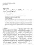
Figure 5: HD distribution of different partition methods for 40-bit
instruction words.
transition on the w bit segment; a w-bit comparator (>)to
compare the Hamming distance with the half of the segment
size; and a w-bit multiplexor (Mux) to choose between the
inverted and uninverted data values.
The area of each component, except for the adder that
has w log(w) area complexity, is linearly proportional to the
number of bits of the input data, w. Since the area of the
adder increases dramatically when its input bit size becomes
large, we want the segment size to be small. This will be used
as a guide in our instruction word segment search algorithm
discussed in the following section.
4. Approach for Segmental Bus-Invert Encoding
Full space search of multiple segments for optimal switching
reduction is a time consuming process since there are a large
number of possibilities. Just for choosing a single segment in
an n-bit instruction space, the number of solutions is
n
i
=2
C
i
n
(note, the segment size can be varied, but at least 2 bits are
required for BI encoding). These solutions will form a huge
search space if n is large and the space increases exponentially
with the word width, n.
Ideally, each solution in the space needs to be investigated
for an optimal solution. To speed up the search process, we
propose to partition the instruction word into several bit
divisions and perform the BI segment search on each of the
divisions. Since the segmental search is based on a set of
narrower bus segments, its search space is much smaller than
that on the full width bus; therefore, the search is fast.
EURASIP Journal on Embedded Systems 5
get instruction execution trace for a given application;
find frequent basic blocks,
B;
find instruction types,
I,inB;
determine divisions,
P,basedonI;
Algorithm 1: Search space partition, partition().
Search Space Partition. There are many ways for the instruc-
tion word bit space partition. We investigated the percentage
of transferred segment words whose Hamming distance is
greater than half the segment size (hence enabling BI oper-
ation to reduce bus switching), for three different partition
cases: one, no partition (NP); two, evenly partitioned (EP);
and three, partition based on the instruction fields. For
the instruc tion set architecture used in our investigation, it
includes four instruction fields: Op, Rs, Rt,andImm.
The results are presented in Figure 5, where the bit
range for a segment is given in the bracket. For the case
without partition (hence only one segment), just 5% of bus
transmissions have more than half of bus bits switching.
In the case of the even partition, the bus is partitioned
into four segments of an equal size, the percentage value
for each segment is below 20%, on average, and only
10% of transmissions have the BI operation. With the
instruction field-based partition, the segment size varies, but
all four segments h ave a higher percentage of BI-enabled
transmissions than other two cases, which allows for more
bit switching reduction if BI encoding is applied. Thus we
base our bit space partition on the instr uction fields.
For an application, its execution can be represented with
a connection of basic blocks. Instructions within a basic
block are executed sequentially. Often, the switching activity
is mainly determined by the frequently executed loop blocks
(named as dominant block in this paper).
To find a partition, we use instruction typ es in the
dominant blocks. Based on those types of instructions, fields
that are sensitive to the input are grouped as one division,
and the other fields are each treated as a separate division.
The partition approach is summarized in Algorithm 1.
BI Segment Search. Given a space partition produced by
Algorithm 1, we search for a bit segment for BI encoding
(henceforth called BI segment ).
For each bit space division, we investigate all bus
segments of different sizes and locations. We use the leftmost
bit of the segment to mark the segment location. For each
location, we start from the smallest segment of a two-bit
window; then we increase the window rightward by 1 bit to
form a new segment. We compare the new segment with the
one currently deemed as the best. If the following condition
is satisfied:
δ
new
− δ
best
>=
(
w
new
− w
best
)
2
, (10)
namely, the extr a w
new
− w
best
bits of the new segment
will statistically increase the switching reduction, the new
segment is recorded as the best segment; otherwise, the new
segment is discarded. After all possible window sizes are
explored for a location, we continue with another segment
location starting from the two-bit window again. This time,
it is possible that δ
new
>δ
best
but w
new
<w
best
holds. In this
case, the new segment with small size w but large δ is always
recorded as the best segment. This process is repeated until
all possible cases are exhausted. The search approach is given
in Algorithm 2. Note that the switching activity of invert
control lines is taken into account for the final switching
reduction rate.
BI Segment Merge. Since a BI segment requires an invert
control line, an overhead for BI encoding, we want to merge
some BI segments that are locally generated within different
bit divisions, in order to save the control lines while keeping
the same or improving switching reduction.
Figure 6 shows an example of merging two code segment
sequences, Seg.1andSeg.2. To calculate the bit switches, we
assume that the initial value on the bus is the first word in the
sequence. The bit switches are generated when the following
words are sent over the bus. The number of bit switches with
and without BI is given below each sequence in the figure.
With BI encoding, no bit switching is saved for Seg.1; for
Seg.2, five bits of switching are saved. If the two segments
are merged (see Merged Seq. in the figure), eight bit switches
can be saved; if we apply BI to the subset of the newly merged
segment, as highlighted in the shaded area, a further 1 bit
switching can be saved. Therefore, for each merge attempt,
we rerun the segment search for the merged segment, using
Algorithm 2.
Since the large segment may result in large invert
control logic as discussed in Section 3.2, we start from small
segments for the merge operation so that after merge we
haveassmallnumberofsegmentsaspossiblewitheach
segment being not expensive. The merge approach is given
in Algorithm 3.
5. Experimental Results
To examine the efficiency of our segmental bus-invert
coding, we applied this approach to a set of applications from
MiBench [14] and compared our approach with the most
related encodings: traditional Bus-Invert [4], Partitioned
Bus-Invert [4], Partial Bus-Invert [7], and Multiway Partial
Bus Invert [7].
Experimental Setup. The experiment setup is g iven in
Figure 7. To simulate our design for a given application, we
use ASIPMeister [15] to generate a processor VHDL model
as the experimental platform for the application. The Sim-
pleScalar PISA [5] has been chosen as the target processor
instruction set architecture. The instruction format of this
architecturecanbeextendedto64bits,but40bitsare
actually used in normal designs. Therefore, our simulations
adopt the 40-bit instruction format.
Theexperimentstartswithagivenapplicationwritten
in C, which is compiled by the SimpleScalar tool and then
6 EURASIP Journal on Embedded Systems
BI seg = Φ;
for each partition, p
∈ P do
δ
best
= 0;
w
best
= 2;
tmp
seg = Φ;
for all bit
sub set, bs(w) ∈ P do
get E(HD), DEV(HD) of bs(w);
δ
= E(HD)+DEV(HD);
if δ>w/2 then
if δ>
= δ
best
then
if w<w
best
then
tmp
seg = bs;
δ
best
= δ;
w
best
= w;
else if δ
− δ
best
>= (w − w
best
)/2 then
tmp
seg = bs;
δ
best
= δ;
w
best
= w;
else
discard bs;
end if
else
discard bs;
end if
else
discard bs;
end if
end for
BI
seg = BI seg ∪ tmp seg;
end for
apply BI on BI
seg;
r
= get switching reductio rate;
Algorithm 2: BI segment search, segSearch (P).
red
best
= r;
sort segments BI
seg ∈ S in the size-ascending order [seg
0
,seg
1
, ,seg
n−1
];
for (i
= 0; i<n− 1; i ++)do
for ( j
= i +1; j<n; j ++)do
seg
k
= seg
i
∪ seg
j
P = (BI seg −seg
i
− seg
j
) ∪seg
k
;
segSearch (P);
ifr
/
<??red
best
then
BI
seg = P;
segMerge (BI
seg);
end if
end for
end for
Algorithm 3: BI segment merge, segMerge (S).
simulated on the processor VHDL model generated by
ASIPMeister. The instruction t race over the inst ruction data
bus is extracted during the simulation. This instruction trace
is used to determine the bus segments for BI encoding based
on our encoding design approach proposed in Section 4.
The related BI encoding/decoding and control logic is then
implemented in the processor VHDL model, which is then
synthesized by Synopsys Design Compiler for area, delay, and
power overhead evaluation based on the Tower 0.18-micron
standard cells [16].
Bus Switching Reduction. Tab le 1 gives the simulation results
obtained for the conventional BI coding (and its extended
EURASIP Journal on Embedded Systems 7
1 1 0 1
0 0 1 1
1 1 0 0
1 0 1 1
0 1 0
0 0 1
1 1 1
1 0 0
0 1 0 1 1 0 1
0 0 1 0 0 1 1
1 1 1 1 1 0 0
1 0 0 1 0 1 1
+
Number of switches
with BI encoding
0 1 0 1 1 0 1
0 0 1 0 0 1 1
1 1 1 1 1 0 0
1 0 0 1 0 1 1
Seg. 1 Seg. 2 Merged segment
Search
after merge
Number of switches
without BI encoding
6
6
5
10
8
16
7
16
Figure 6: Merge example.
Table 1: Results for Bus Switchings Reduction.
Application Total switches Switches/insn. BI %Red.
Parti. BI (S
= 48) PBI (I = 1) MPBI SBI
%Red. I %Red. S %Red. SI%Red. SI
crc32 19675453 10.1 0.2 10.1 24 14.9 9 19.4 20 3 22.7 21 3
dijkstra 89941656 11.5 5.1 15.6 12 16.3 15 24.8 28 4 35.8 20 3
qsort 88290717 10.3 6.5 21.4 24 15.0 26 23.7 28 3 42.1 17 3
cjpeg 115662171 14.0 4.2 13.8 12 7.1 8 13.1 28 3 31.9 19 3
djpeg 19505584 9.5 4.6 16.6 12 6.6 7 17.2 32 4 22.5 20 3
rawcaudio 23261730 10.0 1.7 12.6 24 10.9 12 11.0 32 4 33.9 12 2
rawdaudio 20425528 10.5 6.5 14.3 12 10.8 15 16.6 30 3 32.5 23 3
rijndael 92029948 10.1 2.3 17.1 12 8.1 7 15.2 33 4 22.3 21 3
stringsearch 4820331 11.4 6.6 17.0 12 13.1 25 18.6 27 4 34.6 24 4
yuv420torgb 191314971 8.4 3.1 10.9 12 9.6 25 16.1 24 4 24.7 15 2
Average 66492809 10.6 4.1 14.9 15.6 11.2 15 17.6 28 4 30.3 19 3
ISA
ASIPMeister
Application
GCC
VHDL (syn.)
VHDL (sim.)
Object code
Synopsys
Design Compiler
Bus-invert
logic
ModelSim
Area, power, delay
SBI
Instruction data
trace
Figure 7: Experimental setup.
partitioned BI), the PBI coding (and its extended MPBI),
and our proposed SBI coding approach, for each application
listed in Column 1.
Columns 2 and 3 provide the number of total bit switches
and the average switching bits per instruction for each
application without any bus encoding. The percentage of the
switching reduced with the traditional bus-invert encoding
(BI)ispresentedinColumn4.Weexploreddifferent bus
partitions based on the approach proposed in [4]; the best
result for each application is shown in Columns 5 and 6
(see label Parti. BI in the table). The switching reduction
data from the Partial Bus-Invert encoding (PBI) a nd Multiple
Partial Bus-Invert (MPBI) encoding are shown in Columns 7
and 8, and Columns 9–11, respectively, where %Red stands
for the switching reduction rate, I the number of invert
control bus lines incurred, and S the total number of bus lines
to which the the bus-invert encoding is applied. Columns 12–
14 give the simulation results from our encoding approach
(SBI).
From Tab le 1, we can see that the traditional BI encoding
achieves very little switching reduction (on average, only
4.1%). This ineffectiveness can also be seen from the
other existing encodings: with average reduction rates from
Partitioned BI, PBI, and MPBI being 14.9%, 11.2%, a nd
17.6%, respectively; for some application, the reduction r ate
is as small as just 7.1%. By using our segmental bus-invert
encoding approach, however, we can achieve from 22.3%
up to 42.1% switching reduction. On average, 30.3% bus
switching can be reduced with SBI.
In addition, Column 3 in Table 1 shows that an average
of 10 bus bits switches per instruction, which indicates that,
on average, the number of total bits to be effectively applied
with bus-invert should be around 20. This is because, as
already explained right after (2), only when the Hamming
8 EURASIP Journal on Embedded Systems
Table 2: Area, power, and delay overheads of PBI, MPBI, and SBI VLSI implementation.
Applications
PBI MPBI SBI
area (μm
2
)power(mW)delay(ns)area(μm
2
)power(mW)delay(ns)area(μm
2
) power (mW) delay (ns)
crc32 409 0.30 2.14 1107 1.44 2.40 1114 1.11 1.95
dijkstra 517 0.69 1.81 1488 1.95 1.85 1105 1.52 1.64
qsort 709 1.15 1.87 1266 2.03 2.14 1053 1.27 2.14
cjpeg 393 0.28 2.14 1250 1.62 1.97 1087 1.09 2.14
djpeg 371 0.30 1.95 1545 2.16 2.01 1104 1.39 2.14
rawcaudio 463 0.44 1.44 1562 2.36 2.35 711 0.74 1.95
rawdaudio 517 0.69 2.86 1297 1.73 1.79 1159 1.35 1.85
rijndael 371 0.37 1.95 1478 1.75 2.57 1120 1.24 2.35
stringsearch 693 1.06 1.95 1482 2.39 1.78 1371 1.66 1.95
yuv420torgb 693 1.05 1.95 1419 2.38 1.72 767 1.07 2.57
Average 514 0.63 2.01 1389 1.98 2.06 1059 1.24 2.07
distance is larger than the half of bus width, bus-invert can be
performed to have the switching activity reduced effectively.
This is reflected by our SBI encoding, where S equals 19.
In contrast, the average number of bits applied by BI in
MPBI and PBI is either relatively too high (S
= 28) or too
small (S
= 15), reducing chances for BI operation and the
switching saving from each BI inversion.
Furthermore, looking at the control lines incurred from
each encoding, the table shows that the Partitioned BI is
most expensive, requiring an average of 15.6 invert-control
lines; in contrast, few control lines are required by the other
encodings, including SBI.
BI Control Logic Overheads. Switching reduction is achieved
at the cost of not only extra control lines but also the
associated control logic for each BI segment, thus incurring
in area and power overheads. As BI and Partitioned BI either
have extremely low switching reduction efficiency or incur
too many invert control bus lines which are impractical for
the real design and not suitable for the instruction data bus
switching reduction, we only compare PBI and MPBI with
our approach for encoding/decoding logic overhead in terms
of area (in μm
2
), power (in mW), and delay (in ns) in Table 2 ,
where the area and power values are the total cost, and the
delay is the longest delay, of all BI segments for an encoding.
As can be seen from Tab le 2, PBI is the cheapest and
MPBI is the most expensive in terms of area and power.
The three encodings have a similar delay incurred from
their control logic. Considering their switching reduction
rate presented in Table 1, SBI achieves considerable switching
reduction at a lower cost than MPBI with respect to area and
power. Among the three encodings, PBI is the cheapest to
encode, but it is also the least effective.
Power Savings Estimation. We use the following formula
to estimate the net power savings of SBI, PBI, and MPBI
encodings:
P
save
= 0.5 ∗ C
bus
∗ V
2
dd
∗ f ∗
(
switch./insn.
)
∗ Red% − P
logic
,
(11)
–20
0
3 5 10 15
Bus capacitance (pF)
Comparison of net power saving
20 25 20 35
20
40
0
20
40
Power saving (%)
Switching reduction (%)
PBI. power
PBI. switch
MPBI. power
MPBI. switch
SBI. power
SBI. switch
Figure 8: Estimated power saving over different bus capacitances.
where C
bus
is the bus loa d capacitance, V
dd
the supply
voltage, f the frequency, (switch./insn.) the switched bus bits
per instruction, Red% the switching reduction rate, and P
logic
the encoding/decoding logic power consumption estimated
with the Design Compiler.
The bus capacitance varies with the system architecture
and low-level implementation. The load capacitance of the
off-chip bus is normally multiple orders of magnitude higher
than that of standard cells. Based on the 0.3 pF standard cell
capacitance, the supply voltage (1.8 V), and clock frequency
(100 Mhz) used in Synopsys DesignPower, we calculate
the power savings with different bus capacitances ranging
from 3 to 35 pF. We use the rawdaudio application as an
example in this investigation, and the results are plotted in
Figure 8.
From the figure, it can be seen that SBI brings higher
savings than the other two encodings. With increase of
the bus capacitance, the power saving of each encoding
reaches to their switching reduction rate, as depicted by
the horizontal lines in the figure. For example, when we
conservatively assume 30 pF as load capacitance of the off-
chip bus, 9.5%, 13.2%, and 29.9% of the total dynamic
EURASIP Journal on Embedded Systems 9
power consumption of the instruction data bus can be saved
by coding of PBI, MPBI, and SBI, respectively. However,
when the bus capacitance is decreased to a certain value
(e.g., 3 pF or 10 times of the cell capacitance), SBI still has
a power saving of around 6.3%. But for PBI and MPBI,
power overhead of the encoding/decoding log ic will cancel
out the power saving from the bus switching reduction. If we
further scale the capacitance value down to around 2 pF and
below, it turns out that the logic overhead incurred brings
the power savings to negative values in all PBI, MPBI, and
our proposed SBI, as the power curves indicate. This means
that bus encoding schemes have some limitations and are
not always effective for the on-chip buses especially when the
bus capacitance is very small. On the other hand, the load
capacitance of the off-chip buses are usually very high, and
when they reach two orders of magnitude larger than that
of on-chip cells, the power reduction rate can be approx-
imately the same as the bus switching activity reduction
rate.
Note that our results of power saving by all the bus
invert schemes are based on the 180 nm technology, where
the dynamic (switching) power is dominant. As technology
scales down, leakage power may become significant. How-
ever, a large portion (50% for the current 90 nm down to
45 nm technologies) of power still comes from the dynamic
power [17]; effective power reduction by bus switching
reduction can still be expected.
6. Conclusions
In this paper, we have discussed the switching reduction of
the instruction memory data bus for lower power processor-
based systems with the Harvard architecture.
We found that the data on the instruction data bus have
little temporal correlation, and the randomness of the data
can be hardly exploited by the existing bus encodings due
to its unevenly bit switching distribution. We proposed a
segmental bus-invert encoding that can take the simplicity
of the encoding approach and at the same time effectively
reduce bus switching activity.
Our encoding idea is similar to the multiway partial
bus invert. But we use a different search algorithm for
bus segments so that by applying the bus invert encoding
to each of the segments, we can achieve an average 30%
switching reduction on a set of benchmarks, in contrast
to the 17.6% obtained by MPBI. The power consumption
reduction rate can be achieved approximately the same
accordingly when the load capacitance of the off-chip bus
reaches two orders of the magnitude of the on-chip cell-
capacitance. In addition, compared to the traditional bus
invert encoding, our approach comes with the reduced
area for encoding/decoding logic, with an average of two
more extra control lines. In contrast, MPBI requires three
additional bus control lines.
We would restate that the experiment results presented
in the paper were based on the designs for individual
applications. O ur design approach can be extended to find
a fixed SBI design for a set/domain of applications, which
may be a practical design issue and will be investigated in the
future.
References
[1] S. Mukhopadhyay, C. Neau, R. T. Cakici, A. Agarwal, C. H.
Kim, and K. Roy, “Gate leakage reduction for scaled devices
using transistor stacking,” IEEE Transactions on Very Large
Scale Integration (VLSI) Systems, vol. 11, no. 4, pp. 716–730,
2003.
[2] L. B enini, G. de Micheli, E. Macii, D. Sciuto, and C.
Silvano, “Asymptotic zerotransition activity encoding for
address busses in low-power microprocessor-based systems,”
in Proceedings of the 7th IEEE Great Lakes Symposium on VLSI,
pp. 77–82, 1997.
[3] C L. Su, C Y. Tsui, and A. M. Despain, “Saving power in the
control path of embedded processors,” IEEE Design and Test of
Computers, vol. 11, no. 4, pp. 24–30, 1994.
[4] M. R. Stan and W. P. Burleson, “Bus-invert coding for low
power i/o,” IEEE Transactions on Very Large Scale Integration
(VLSI) Systems, vol. 3, no. 1, pp. 49–58, 1995.
[5] D. Burger and T. M. Austin, “The Simplescalar Tool Set,
Version 2.0,” Tech. Rep. CS-TR-1997-1342, Department of
Computer Science, University of Wisconsin, Madison, Wis,
USA, 1997.
[6]J.HenkelandH.Lekatsas,“A
2
BC : adaptive address bus
coding for low power deep sub-micron designs,” in Proceedings
of the 38th Annual Design Automation Conference (DAC ’01),
pp. 744–749, 2001.
[7] Y. Shin, S I. Chae, and K. Choi, “Partial bus-invert coding
for power optimization of application-specific systems,” IEEE
Transactions on Very Large Scale Integration (VLSI) Systems,
vol. 9, no. 2, pp. 377–383, 2001.
[8] S. Ramprasad, N. R. Shanbhag, and I. N. Hajj, “A coding
framework for low-power address and data busses,” IEEE
Transactions on Very Large Scale Integration (VLSI) Systems,
vol. 7, no. 2, pp. 212–221, 1999.
[9] T. Lv, J. Henkel, H. Lekatsas, and W. Wolf, “A dictionary-
based en/decoding scheme for low-power data buses,” IEEE
Transactions on Very Large Scale Integration (VLSI) Systems,
vol. 11, no. 5, pp. 943–951, 2003.
[10] A. Wolfe and A. Chanin, “Executing compressed programs
on an embedded RISC architecture,” in Proceedings of the
25th Annual International Symposium on Microarchitecture
(MICRO ’92), pp. 81–91, 1992.
[11] H. Lekatsas, J. Henkel, and W. Wolf, “Code compression for
low power embedded system design,” in Proceedings of the 37th
Design Automation Conference (DAC ’00), pp. 294–299, 2000.
[12] H.Lekatsas,J.Henkel,andW.Wolf,“Approximatearithmetic
coding for bus transition reduction in low power designs,”
IEEE Transactions on Very Large Scale Integration (VLSI)
Systems, vol. 13, no. 6, pp. 696–706, 2005.
[13] P. Petrov and A. Orailoglu, “Low-power instruction bus
encoding for embedded processors,” IEEE Transactions on Very
Large Scale Integration (VLSI) Systems, vol. 12, no. 8, pp. 812–
826, 2004.
[14] M. R. Guthaus, J. S. Ringenberg, D. Ernst, T. M. Austin, T.
Mudge, and R. B. Brown, “Mibench: a free, commercially
representative embedded benchmark suite,” in Proceedings of
the IEEE 4th Annual Workshop on Workload Characterizat ion ,
pp. 83–94, 2001.
[15] A.Kitajima,M.Itoh,J.Sato,A.Shiomi,Y.Takeuchi,andM.
Imai, “Effectiveness of the asip design system peas-iii in design
10 EURASIP Journal on Embedded Systems
of pipelined processors,” in Proceedings of the Asia and South
Pacific Design Automation Conference (ASP-DAC ’01), pp. 649–
654, 2001.
[16] .
[17] N. S. Kim, K. Flautner, D. Blaauw, and T. Mudge, “Circuit
and microarchitectural techniques for reducing cache leakage
power,” IEEE Transactions on Very Large Scale Integration
(VLSI) Systems, vol. 12, no. 2, pp. 167–184, 2004.