Electric Machinery Fundamentals Power & Energy_8 ppt
Bạn đang xem bản rút gọn của tài liệu. Xem và tải ngay bản đầy đủ của tài liệu tại đây (1.28 MB, 22 trang )
149
Chapter 6:
Synchronous Motors
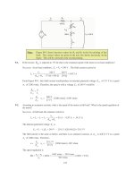
6-1. A 480-V, 60 Hz, four-pole synchronous motor draws 50 A from the line at unity power factor and full
load. Assuming that the motor is lossless, answer the following questions:
(a) What is the output torque of this motor? Express the answer both in newton-meters and in pound-feet.
(b) What must be done to change the power factor to 0.8 leading? Explain your answer, using phasor
diagrams.
(c) What will the magnitude of the line current be if the power factor is adjusted to 0.8 leading?
S
OLUTION
(a) If this motor is assumed lossless, then the input power is equal to the output power. The input power
to this motor is
()()()
IN
3 cos 3 480 V 50 A 1.0 41.6 kW
TL
PVI
θ
== =
The output torque would be
()
OUT
LOAD
41.6 kW
221 N m
1 min 2 rad
1800 r/min
60 s 1 r
m
P
τ
π
ω
== = ⋅
In English units,
(
)
(
)
()
OUT
LOAD
7.04 41.6 kW
7.04
163 lb ft
1800 r/min
m
P
n
τ
== =⋅
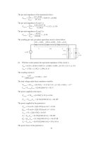
(b) To change the motor’s power factor to 0.8 leading, its field current must be increased. Since the
power supplied to the load is independent of the field current level, an increase in field current increases
A
E
while keeping the distance
δ
sin
A
E
constant. This increase in
A
E
changes the angle of the current
A
I , eventually causing it to reach a power factor of 0.8 leading.
V
φ
E
A
1
jX
S
I
A
E
A
2
I
A
2
I
A
1
Q
∝
I
sin
θ
A
}
∝
P
}
∝
P
(c) The magnitude of the line current will be
()()
41.6 kW
62.5 A
3 PF 3 480 V 0.8
L
T
P
I
V
== =
6-2. A 480-V, 60 Hz, 400-hp 0.8-PF-leading six-pole
∆
-connected synchronous motor has a synchronous
reactance of 1.1 Ω and negligible armature resistance. Ignore its friction, windage, and core losses for the
purposes of this problem.
150
(a) If this motor is initially supplying 400 hp at 0.8 PF lagging, what are the magnitudes and angles of
E
A
and
I
A
?
(b) How much torque is this motor producing? What is the torque angle
δ
? How near is this value to the
maximum possible induced torque of the motor for this field current setting?
(c) If
E
A
is increased by 15 percent, what is the new magnitude of the armature current? What is the
motor’s new power factor?
(d) Calculate and plot the motor’s V-curve for this load condition.
S
OLUTION
(a) If losses are being ignored, the output power is equal to the input power, so the input power will be
()( )
IN
400 hp 746 W/hp 298.4 kWP ==
This situation is shown in the phasor diagram below:
V
φ
E
A
jX
S
I
A
I
A
The line current flow under these circumstances is
()()
298.4 kW
449 A
3 PF 3 480 V 0.8
L
T
P
I
V
== =
Because the motor is
∆
-connected, the corresponding phase current is
449 / 3 259 A
A
I ==
. The angle of
the current is
()
1
cos 0.80 36.87
−
−=−°, so 259 36.87 A
A
=∠− °I . The internal generated voltage
A
E is
ASA
jX
φ
=−EV I
()()( )
480 0 V 1.1 259 36.87 A 384 36.4 V
A
j=∠°− Ω ∠− °=∠−°E
(b) This motor has 6 poles and an electrical frequency of 60 Hz, so its rotation speed is
m
n = 1200 r/min.
The induced torque is
()
OUT
ind
298.4 kW
2375 N m
1 min 2 rad
1200 r/min
60 s 1 r
m
P
τ
π
ω
== = ⋅
The maximum possible induced torque for the motor at this field setting is
()()
()
()
ind,max
3
3 480 V 384 V
4000 N m
1 min 2 rad
1200 r/min 1.1
60 s 1 r
A
mS
VE
X
φ
τ
π
ω
== =⋅
Ω
(c) If the magnitude of the internal generated voltage
A
E
is increased by 15%, the new torque angle can
be found from the fact that
constantsin =∝ PE
A
δ
.
()
21
1.15 1.15 384 V 441.6 V
AA
EE== =
151
()
11
1
21
2
384 V
sin sin sin sin 36.4 31.1
441.6 V
A
A
E
E
δδ
−−
== −°=−°
The new armature current is
2
2
480 0 V 441.6 31.1 V
227 24.1 A
1.1
A
A
S
jX j
φ
−
∠° − ∠− °
== =∠−°
Ω
VE
I
The magnitude of the armature current is 227 A, and the power factor is cos (-24.1°) = 0.913 lagging.
(d) A MATLAB program to calculate and plot the motor’s V-curve is shown below:
% M-file: prob6_2d.m
% M-file create a plot of armature current versus Ea
% for the synchronous motor of Problem 6-2.
% Initialize values
Ea = (1:0.01:1.70)*384; % Magnitude of Ea volts
Ear = 384; % Reference Ea
deltar = -36.4 * pi/180; % Reference torque angle
Xs = 1.1; % Synchronous reactance
Vp = 480; % Phase voltage at 0 degrees
Ear = Ear * (cos(deltar) + j * sin(deltar));
% Calculate delta2
delta2 = asin ( abs(Ear) ./ abs(Ea) .* sin(deltar) );
% Calculate the phasor Ea
Ea = Ea .* (cos(delta2) + j .* sin(delta2));
% Calculate Ia
Ia = ( Vp - Ea ) / ( j * Xs);
% Plot the v-curve
figure(1);
plot(abs(Ea),abs(Ia),'b','Linewidth',2.0);
xlabel('\bf\itE_{A}\rm\bf (V)');
ylabel('\bf\itI_{A}\rm\bf (A)');
title ('\bfSynchronous Motor V-Curve');
grid on;
152
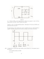
The resulting plot is shown below
350 400 450 500 550 600 650 700
200
210
220
230
240
250
260
E
A
(V)
I
A
(A)
Synchronous Motor V-Curve
6-3. A 2300-V 1000-hp 0.8-PF leading 60-Hz two-pole Y-connected synchronous motor has a synchronous
reactance of 2.8 Ω and an armature resistance of 0.4 Ω. At 60 Hz, its friction and windage losses are 24
kW, and its core losses are 18 kW. The field circuit has a dc voltage of 200 V, and the maximum
I
F
is 10
A. The open-circuit characteristic of this motor is shown in Figure P6-1. Answer the following questions
about the motor, assuming that it is being supplied by an infinite bus.
(a) How much field current would be required to make this machine operate at unity power factor when
supplying full load?
(b) What is the motor’s efficiency at full load and unity power factor?
(c) If the field current were increased by 5 percent, what would the new value of the armature current be?
What would the new power factor be? How much reactive power is being consumed or supplied by the
motor?
(d) What is the maximum torque this machine is theoretically capable of supplying at unity power factor?
At 0.8 PF leading?
Note: An electronic version of this open circuit characteristic can be found in file
p61_occ.dat, which can be used with MATLAB programs. Column 1
contains field current in amps, and column 2 contains open-circuit terminal
voltage in volts.
153
S
OLUTION
(a) At full load, the input power to the motor is
CUcoremechOUTIN
PPPPP +++=
We can’t know the copper losses until the armature current is known, so we will find the input power and
armature current ignoring that term, and then correct the input power after we know it.
()( )
IN
1000 hp 746 W/hp 24 kW 18 kW 788 kWP =++=
Therefore, the line and phase current at unity power factor is
()()
788 kW
198 A
3 PF 3 2300 V 1.0
AL
T
P
II
V
== = =
The copper losses due to a current of 198 A are
()()
2
2
CU
3 3 198 A 0.4 47.0 kW
AA
PIR== Ω=
Therefore, a better estimate of the input power at full load is
()( )
IN
1000 hp 746 W/hp 24 kW 18 kW 47 kW 835 kWP =+++=
and a better estimate of the line and phase current at unity power factor is
154
()()
835 kW
210 A
3 PF 3 2300 V 1.0
AL
T
P
II
V
== = =
The phasor diagram of this motor operating a unity power factor is shown below:
jX
S
I
A
V
φ
I
A
E
A
I
A
R
A
The phase voltage of this motor is 2300 /
3
= 1328 V. The required internal generated voltage is
AAASA
RjX
φ
=− −EV I I
()( )()( )
1328 0 V 0.4 210 0 A 2.8 210 0 A
A
j=∠°−Ω∠°− Ω∠°E
1376 25.3 V
A
=∠−°E
This internal generated voltage corresponds to a terminal voltage of
()
3 1376 2383 V=
. This voltage
would require a field current of 4.6 A.
(b) The motor’s efficiency at full load and unity power factor is
OUT
IN
746 kW
100% 100% 89.3%
835 kW
P
P
η
=× = × =
(c) To solve this problem, we will temporarily ignore the effects of the armature resistance
A
R
. If
A
R
is
ignored, then
δ
sin
A
E is directly proportional to the power supplied by the motor. Since the power
supplied by the motor does not change when
F
I is changed, this quantity will be a constant.
If the field current is increased by 5%, then the new field current will be 4.83 A, and the new value of
the open-circuit terminal voltage will be 2450 V. The new value of
A
E
will be 2450 V /
3
= 1415 V.
Therefore, the new torque angle
δ
will be
()
11
1
21
2
1376 V
sin sin sin sin 25.3 24.6
1415 V
A
A
E
E
δδ
−−
== −°=−°
Therefore, the new armature current will be
1328 0 V 1415 -25.3 V
214.5 3.5 A
0.4 2.8
A
A
AS
RjX j
φ
−
∠° − ∠ °
== =∠°
++Ω
VE
I
The new current is about the same as before, but the phase angle has become positive. The new power
factor is cos 3.5
°
= 0.998 leading, and the reactive power supplied by the motor is
(
)
(
)
(
)
3 sin 3 2300 V 214.5 A sin 3.5 52.2 kVAR
TL
QVI
θ
== °=
(d) The maximum torque possible at unity power factor (ignoring the effects of
A
R ) is:
(
)
(
)
() ()
ind,max
3
3 1328 V 1376 V
5193 N m
1 min 2 rad
3600 r/min 2.8
60 s 1 r
A
mS
VE
X
φ
τ
π
ω
== =⋅
Ω
155
If we are ignoring the resistance of the motor, then the input power would be 788 kW (note that copper
losses are ignored!). At a power factor of 0.8 leading, the current flow will be
()()
788 kW
247 A
3 PF 3 2300 V 0.8
AL
T
P
II
V
== = =
so
247 36.87 A
A
=∠ °I
. The internal generated voltage at 0.8 PF leading (ignoring copper losses) is
AAASA
RjX
φ
=− −EV I I
()( )
1328 0 V 2.8 247 36.87 A
A
j=∠°− Ω ∠ °E
1829 17.6 V
A
=∠−°E
Therefore, the maximum torque at a power factor of 0.8 leading is
(
)
(
)
() ()
ind,max
3
3 1328 V 1829 V
6093 N m
1 min 2 rad
3600 r/min 2.8
60 s 1 r
A
mS
VE
X
φ
τ
π
ω
== =⋅
Ω
6-4.
Plot the V-curves (
I
A
versus
I
F
) for the synchronous motor of Problem 6-3 at no-load, half-load, and full-
load conditions. (Note that an electronic version of the open-circuit characteristics in Figure P6-1 is
available at the book’s Web site. It may simplify the calculations required by this problem. Also, you may
assume that
A
R is negligible for this calculation.)
S
OLUTION
The input power at no-load, half-load and full-load conditions is given below. Note that we are
assuming that
A
R is negligible in each case.
IN,nl
24 kW 18 kW 42 kWP =+ =
()( )
IN,half
500 hp 746 W/hp 24 kW 18 kW 373 kWP =++=
()( )
IN,full
1000 hp 746 W/hp 24 kW 18 kW 788 kWP =++=
If the power factor is adjusted to unity, then armature currents will be
()()
,nl
42 kW
10.5 A
3 PF 3 2300 V 1.0
A
T
P
I
V
== =
()()
,fl
373 kW
93.6 A
3 PF 3 2300 V 1.0
A
T
P
I
V
== =
()()
,fl
788 kW
198 A
3 PF 3 2300 V 1.0
A
T
P
I
V
== =
The corresponding internal generated voltages at unity power factor are:
ASA
jX
φ
=−EV I
(
)
(
)
,nl
1328 0 V 2.8 10.5 0 A 1328.3 1.27 V
A
j=∠°− Ω ∠°= ∠−°E
()( )
,half
1328 0 V 1.5 93.6 0 A 1354 11.2 V
A
j=∠°− Ω ∠°=∠−°E
(
)
(
)
,full
1328 0 V 2.8 198 0 A 1439 22.7 V
A
j=∠°− Ω∠°=∠−°E
These values of
A
E and
δ
at unity power factor can serve as reference points in calculating the
synchronous motor V-curves. The MATLAB program to solve this problem is shown below:
156
% M-file: prob6_4.m
% M-file create a plot of armature current versus field
% current for the synchronous motor of Problem 6-4 at
% no-load, half-load, and full-load.
% First, initialize the field current values (21 values
% in the range 3.8-5.8 A)
If = 2.5:0.1:8;
% Get the OCC
load p61_occ.dat;
if_values = p61_occ(:,1);
vt_values = p61_occ(:,2);
% Now initialize all other values
Xs = 1.5; % Synchronous reactance
Vp = 1328; % Phase voltage
% The following values of Ea and delta are for unity
% power factor. They will serve as reference values
% when calculating the V-curves.
d_nl = -1.27 * pi/180; % delta at no-load
d_half = -11.2 * pi/180; % delta at half-load
d_full = -22.7 * pi/180; % delta at full-load
Ea_nl = 1328.3; % Ea at no-load
Ea_half = 1354; % Ea at half-load
Ea_full = 1439; % Ea at full-load
%%%%%%%%%%%%%%%%%%%%%%%%%%%%%%%%%%%%%%%%%%%%%%%%%%%%%%
% Calculate the actual Ea corresponding to each level
% of field current
%%%%%%%%%%%%%%%%%%%%%%%%%%%%%%%%%%%%%%%%%%%%%%%%%%%%%%
Ea = interp1(if_values,vt_values,If) / sqrt(3);
%%%%%%%%%%%%%%%%%%%%%%%%%%%%%%%%%%%%%%%%%%%%%%%%%%%%%%
% Calculate the armature currents associated with
% each value of Ea for the no-load case.
%%%%%%%%%%%%%%%%%%%%%%%%%%%%%%%%%%%%%%%%%%%%%%%%%%%%%%
% First, calculate delta.
delta = asin ( Ea_nl ./ Ea .* sin(d_nl) );
% Calculate the phasor Ea
Ea2 = Ea .* (cos(delta) + j .* sin(delta));
% Now calculate Ia
Ia_nl = ( Vp - Ea2 ) / (j * Xs);
%%%%%%%%%%%%%%%%%%%%%%%%%%%%%%%%%%%%%%%%%%%%%%%%%%%%%%
% Calculate the armature currents associated with
% each value of Ea for the half-load case.
%%%%%%%%%%%%%%%%%%%%%%%%%%%%%%%%%%%%%%%%%%%%%%%%%%%%%%
% First, calculate delta.
delta = asin ( Ea_half ./ Ea .* sin(d_half) );
% Calculate the phasor Ea
Ea2 = Ea .* (cos(delta) + j .* sin(delta));
157
% Now calculate Ia
Ia_half = ( Vp - Ea2 ) / (j * Xs);
%%%%%%%%%%%%%%%%%%%%%%%%%%%%%%%%%%%%%%%%%%%%%%%%%%%%%%
% Calculate the armature currents associated with
% each value of Ea for the full-load case.
%%%%%%%%%%%%%%%%%%%%%%%%%%%%%%%%%%%%%%%%%%%%%%%%%%%%%%
% First, calculate delta.
delta = asin ( Ea_full ./ Ea .* sin(d_full) );
% Calculate the phasor Ea
Ea2 = Ea .* (cos(delta) + j .* sin(delta));
% Now calculate Ia
Ia_full = ( Vp - Ea2 ) / (j * Xs);
%%%%%%%%%%%%%%%%%%%%%%%%%%%%%%%%%%%%%%%%%%%%%%%%%%%%%%
% Plot the v-curves
%%%%%%%%%%%%%%%%%%%%%%%%%%%%%%%%%%%%%%%%%%%%%%%%%%%%%%
plot(If,abs(Ia_nl),'k-','Linewidth',2.0);
hold on;
plot(If,abs(Ia_half),'b ','Linewidth',2.0);
plot(If,abs(Ia_full),'r:','Linewidth',2.0);
xlabel('\bfField Current (A)');
ylabel('\bfArmature Current (A)');
title ('\bfSynchronous Motor V-Curve');
grid on;
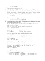
The resulting plot is shown below. The flattening visible to the right of the V-curves is due to magnetic
saturation in the machine.
6-5. If a 60-Hz synchronous motor is to be operated at 50 Hz, will its synchronous reactance be the same as at
60 Hz, or will it change? (Hint: Think about the derivation of
X
S
.)
158
S
OLUTION
The synchronous reactance represents the effects of the armature reaction voltage
stat
E and the
armature self-inductance. The armature reaction voltage is caused by the armature magnetic field
S
B
, and
the amount of voltage is directly proportional to the speed with which the magnetic field sweeps over the
stator surface. The higher the frequency, the faster
S
B sweeps over the stator, and the higher the armature
reaction voltage
stat
E
is. Therefore, the armature reaction voltage is directly proportional to frequency.
Similarly, the reactance of the armature self-inductance is directly proportional to frequency, so the total
synchronous reactance
X
S
is directly proportional to frequency. If the frequency is changed from 60 Hz to
50 Hz, the synchronous reactance will be decreased by a factor of 5/6.
6-6. A 480-V 100-kW 0.85-PF leading 50-Hz six-pole Y-connected synchronous motor has a synchronous
reactance of 1.5 Ω and a negligible armature resistance. The rotational losses are also to be ignored. This
motor is to be operated over a continuous range of speeds from 300 to 1000 r/min, where the speed changes
are to be accomplished by controlling the system frequency with a solid-state drive.
(a) Over what range must the input frequency be varied to provide this speed control range?
(b) How large is
E
A
at the motor’s rated conditions?
(c) What is the maximum power the motor can produce at the rated conditions?
(d) What is the largest
E
A
could be at 300 r/min?
(e) Assuming that the applied voltage
V
φ
is derated by the same amount as E
A
, what is the maximum
power the motor could supply at 300 r/min?
(f) How does the power capability of a synchronous motor relate to its speed?
S
OLUTION
(a) A speed of 300 r/min corresponds to a frequency of
(
)
(
)
300 r/min 6
15 Hz
120 120
m
e
nP
f == =
A speed of 1000 r/min corresponds to a frequency of
()()
1000 r/min 6
50 Hz
120 120
m
e
nP
f
== =
The frequency must be controlled in the range 15 to 50 Hz.
(b) The armature current at rated conditions is
()()
100 kW
141.5 A
3 PF 3 480 V 0.85
AL
T
P
II
V
== = =
so 141.5 31.8 A
A
=∠°I . This machine is Y-connected, so the phase voltage is V
φ
= 480 /
3
= 277 V.
The internal generated voltage is
AAASA
RjX
φ
=− −EV I I
()( )
277 0 V 1.5 141.5 31.8 A
A
j=∠°− Ω ∠°E
429 24.9 V
A
=∠− °E
So
A
E
= 429 V at rated conditions.
(c) The maximum power that the motor can produce at rated speed with the value of
A
E from part (b) is
159
()()
max
3
3 277 V 429 V
238 kW
1.5
A
S
VE
P
X
φ
== =
Ω
(d) Since
A
E
must be decreased linearly with frequency, the maximum value at 300 r/min would be
()
,300
15 Hz
429 V 129 V
50 Hz
A
E
==
(e) If the applied voltage
φ
V is derated by the same amount as
A
E , then V
φ
= (15/50)(277) = 83.1 V.
Also, note that
S
X
= (15/50)(1.5 Ω) = 0.45 Ω. The maximum power that the motor could supply would
be
()()
max
3
3 83.1 V 129 V
71.5 kW
0.45
A
S
VE
P
X
φ
== =
Ω
(f) As we can see by comparing the results of (c) and (e), the power-handling capability of the
synchronous motor varies linearly with the speed of the motor.
6-7. A 208-V Y-connected synchronous motor is drawing 40 A at unity power factor from a 208-V power
system. The field current flowing under these conditions is 2.7 A. Its synchronous reactance is 0.8 Ω.
Assume a linear open-circuit characteristic.
(a) Find the torque angle
δ
.
(b) How much field current would be required to make the motor operate at 0.8 PF leading?
(c) What is the new torque angle in part (b)?
S
OLUTION
(a) The phase voltage of this motor is
V
φ
= 120 V, and the armature current is
40 0 A
A
=∠°I
.
Therefore, the internal generated voltage is
AAASA
RjX
φ
=− −EV I I
()( )
120 0 V 0.8 40 0 A
A
j=∠°− Ω ∠°E
124 14.9 V
A
=∠−°E
The torque angle
δ
of this machine is –14.9
°
.
(b) A phasor diagram of the motor operating at a power factor of 0.78 leading is shown below.
V
φ
E
A
1
jX
S
I
A
E
A
2
I
A
2
I
A
1
}
∝
P
}
∝
P
Since the power supplied by the motor is constant, the quantity
θ
cos
A
I
, which is directly proportional to
power, must be constant. Therefore,
()( )( )
2
0.8 40 A 1.00
A
I =
160
2
50 36.87 A
A
=∠ °I
The internal generated voltage required to produce this current would be
222AAASA
RjX
φ
=− −EV I I
()( )
2
120 0 V 0.8 50 36.87 A
A
j=∠°− Ω ∠ °E
2
147.5 12.5 V
A
=∠−°E
The internal generated voltage
A
E
is directly proportional to the field flux, and we have assumed in this
problem that the flux is directly proportional to the field current. Therefore, the required field current is
()
2
21
1
147 V
2.7 A 3.20 A
124 V
A
FF
A
E
II
E
== =
(c) The new torque angle
δ
of this machine is –12.5
°
.
6-8. A synchronous machine has a synchronous reactance of 2.0
Ω
per phase and an armature resistance of 0.4
Ω
per phase. If
E
A
=460
∠
-8
°
V and
φ
V
= 480
∠
0
°
V, is this machine a motor or a generator? How
much power P is this machine consuming from or supplying to the electrical system? How much reactive
power Q is this machine consuming from or supplying to the electrical system?
S
OLUTION
This machine is a motor, consuming power from the power system, because
A
E
is lagging
φ
V
.
It is also consuming reactive power, because cos
A
EV
φ
δ
< . The current flowing in this machine is
480 0 V 460 8 V
33.6 9.6 A
0.4 2.0
A
A
AS
RjX j
φ
−
∠° − ∠−°
== =∠−°
++Ω
VE
I
Therefore the real power consumed by this motor is
()( )()
3 cos 3 480 V 33.6 A cos 9.6 47.7 kW
A
PVI
φ
θ
== °=
and the reactive power consumed by this motor is
()( )()
3 sin 3 480 V 33.6 A sin 9.6 8.07 kVAR
A
QVI
φ
θ
== °=
6-9. Figure P6-2 shows a synchronous motor phasor diagram for a motor operating at a leading power factor
with no
R
A
. For this motor, the torque angle is given by
cos
tan =
sin
SA
SA
XI
VXI
φ
θ
δ
θ
+
-1
cos
=tan
sin
SA
SA
XI
VXI
φ
θ
δ
θ
+
Derive an equation for the torque angle of the synchronous motor if the armature resistance is included.
161
S
OLUTION
The phasor diagram with the armature resistance considered is shown below.
jX
S
I
A
V
φ
I
A
E
A
I
A
R
A
I
A
R
A
cos
θ
θ
θ
θ
X
S
I
A
sin
θ
}
X
S
I
A
cos
θ
}
}
δ
Therefore,
cos sin
tan
sin cos
SA AA
SA AA
XI RI
VXI RI
φ
θθ
δ
θθ
+
=
+−
1
cos sin
tan
sin cos
SA AA
SA AA
XI RI
VXI RI
φ
θθ
δ
θθ
−
+
=
+−
6-10. A 480-V 375-kVA 0.8-PF-lagging Y-connected synchronous generator has a synchronous reactance of 0.4
Ω and a negligible armature resistance. This generator is supplying power to a 480-V 80-kW 0.8-PF-
leading Y-connected synchronous motor with a synchronous reactance of 1.1
Ω
and a negligible armature
resistance. The synchronous generator is adjusted to have a terminal voltage of 480 V when the motor is
drawing the rated power at unity power factor.
(a) Calculate the magnitudes and angles of
A
E for both machines.
(b) If the flux of the motor is increased by 10 percent, what happens to the terminal voltage of the power
system? What is its new value?
(c) What is the power factor of the motor after the increase in motor flux?
S
OLUTION
(a) The motor is operating at rated power and unity power factor, so the current flowing in the motor is
()()
,m ,m
80 kW
96.2 A
3 PF 3 480 V 1.0
AL
T
P
II
V
== = =
so
,m
96.2 0 A
A
=∠°I . This machine is Y-connected, so the phase voltage is V
φ
= 480 / 3 = 277 V. The
internal generated voltage of the motor is
162
,m ,m ,mASA
jX
φ
=−EV I
()( )
,m
277 0 V 1.1 96.2 0 A
A
j=∠°− Ω ∠°E
,m
297 20.9 V
A
=∠− °E
This same current comes from the generator, so the internal generated voltage of the generator is
,g ,g ,gASA
jX
φ
=+EV I
()( )
,g
277 0 V 0.4 96.2 0 A
A
j=∠°+ Ω ∠°E
,g
280 7.9 V
A
=∠°E
+
-
E
A,g
j
0.4
Ω
+
-
V
φ
,m
I
A,g
+
-
I
A,m
E
A,m
j
1.1
Ω
+
-
V
φ
,g
I
A
jX
S,m
V
φ
I
A
E
A,m
jX
S,g
I
A
V
φ
I
A
E
A,g
Generator
Motor
(b) The power supplied by the generator to the motor will be constant as the field current of the motor is
varied. The 10% increase in flux will raise the internal generated voltage of the motor to (1.1)(297 V) =
327 V.
To make finding the new conditions easier, we will make the angle of the phasor
,Ag
E
the reference during
the following calculations. The resulting phasor diagram is shown below.
I
A
jX
S,m
V
φ
I
A
E
A
,
m
jX
S,g
I
A
E
A,g
δ
m
δ
g
Then by Kirchhoff’s Voltage Law,
,, ,,
()
Ag Am S g Sm A
jX X=+ +EE I
163
or
,,
,,
()
Ag Am
A
Sg Sm
jX X
−
=
+
EE
I
Note that this combined phasor diagram looks just like the diagram of a synchronous motor, so we can
apply the power equation for synchronous motors to this system.
,,
,,
3
sin
Ag Am
Sg Sm
EE
P
XX
γ
=
+
where
gm
γ
δδ
=+. From this equation,
()
()( )
()( )
,,
11
,,
1.5 80 kW
sin sin 25.9
3 3 280V 327 V
Sg Sm
Ag Am
XXP
EE
γ
−−
+
Ω
== =°
Therefore,
,,
,,
280 0 V 327 25.9 V
95.7 5.7 A
() 1.5
Ag Am
A
Sg Sm
jX X j
−
∠° − ∠− °
== =∠°
+Ω
EE
I
The phase voltage of the system would be
(
)
(
)
,,
280 0 V 0.4 95.7 5.7 A 286 7.6 V
Ag Sg A
jX j
φ
=− =∠°− Ω ∠°=∠−°VE I
If we make
φ
V
the reference (as we usually do), these voltages and currents become:
,
280 7.6 V
Ag
=∠°E
286 0 V
φ
=∠°V
,
327 18.3 V
Am
=∠−°E
95.7 13.3 A
A
=∠°I
The new terminal voltage is
()
3286 V 495 V
T
V ==
, so the system voltage has increased.
(c) The power factor of the motor is now
()
PF cos 13.3 0.973 leading=−°=
, since a current angle of
-18.3
°
implies an impedance angle of 18.3
°
.
Note: The reactive power in the motor is now
()( )( )
motor
3 sin 3 286 V 95.7 A sin 13.3 18.9 kVAR
A
QVI
φ
θ
== −°=−
The motor is now supplying 18.9 kVAR to the system. Note that an increase in machine flux has
increased the reactive power supplied by the motor and also raised the terminal voltage of the system.
This is consistent with what we learned about reactive power sharing in Chapter 5.
6-11. A 480-V, 100-kW, 50-Hz, four-pole, Y-connected synchronous motor has a rated power factor of 0.85
leading. At full load, the efficiency is 91 percent. The armature resistance is 0.08
Ω
, and the synchronous
reactance is 1.0
Ω
. Find the following quantities for this machine when it is operating at full load:
(a) Output torque
(b) Input power
(c)
m
n
(d)
A
E
164
(e)
A
I
(f)
conv
P
(g)
mech core stray
PPP++
S
OLUTION
(a) Since this machine has 8 poles, it rotates at a speed of
(
)
120 50 Hz
120
1500 r/min
4
e
m
f
n
P
== =
If the output power is 100 kW, the output torque is
()
()
out
load
m
100,000 W
637 N m
2 rad 1 min
1500 r/min
1 r 60 s
P
τ
π
ω
== = ⋅
(b) The input power is
OUT
IN
100 kW
110 kW
0.91
P
P
η
== =
(c) The mechanical speed is
1500 r/min
m
n =
(d) The armature current is
()()
110 kW
156 A
3 PF 3 480 V 0.85
AL
T
P
II
V
== = =
156 31.8 A
A
=∠°I
Therefore,
A
E is
AAASA
RjX
φ
=− −EV I I
()()()()()
277 0 V 0.08 156 31.8 A 1.0 156 31.8 A
A
j=∠°− Ω∠°− Ω∠°E
375 21.8 V
A
=∠− °E
(e) The magnitude of the armature current is 375 A.
(f) The power converted from electrical to mechanical form is given by the equation
conv IN CU
PPP=−
()( )
2
2
CU
3 3 156 A 0.08 5.8 kW
AA
PIR== Ω=
conv IN CU
110 kW 5.8 kW 104.2 kWPPP=− = − =
(g) The mechanical, core, and stray losses are given by the equation
mech core stray conv OUT
104.2 kW 100 kW 4.2 kWPPPPP++=−= − =
6-12. The Y-connected synchronous motor whose nameplate is shown in Figure 6-21 has a per-unit synchronous
reactance of 0.90 and a per-unit resistance of 0.02.
(a) What is the rated input power of this motor?
(b) What is the magnitude of
A
E at rated conditions?
165
(c) If the input power of this motor is 10 MW, what is the maximum reactive power the motor can
simultaneously supply? Is it the armature current or the field current that limits the reactive power
output?
(d) How much power does the field circuit consume at the rated conditions?
(e) What is the efficiency of this motor at full load?
(f) What is the output torque of the motor at the rated conditions? Express the answer both in newton-
meters and in pound-feet.
S
OLUTION
The base quantities for this motor are:
,base
6600 V
T
V =
,base
6600 V
3811 V
3
V
φ
==
,base ,base
1404 A
AL
II==
()()()
base rated
3 PF 3 6600 V 1404 A 1.0 16.05 MW
TL
SP VI== = =
(a) The rated input power of this motor is
()()()
IN
3 PF 3 6600 V 1404 A 1.0 16.05 MW
TL
PVI== =
(b) At rated conditions,
1.0 0 pu
φ
=∠°V and 1.0 0 pu
φ
=∠°I , so
A
E is given in per-unit quantities as
AAASA
RjX
φ
=− −EV I I
()()( )()()
1 0 0.02 1.0 0 0.90 1 0
A
j=∠°− ∠°− ∠°E
1.33 42.6 pu
A
=∠−°E
The base phase voltage of this motor is 6600 /
3
= 3810 V, so
A
E is
()()
1.33 42.6 3810 V 5067 42.6 V
A
=∠−° =∠−°E
(c) From the capability diagram, we know that there are two possible constraints on the maximum
reactive power—the maximum stator current and the maximum rotor current. We will have to check each
one separately, and limit the reactive power to the lesser of the two limits.
The stator apparent power limit defines a maximum safe stator current. This limit is the same as the rated
input power for this motor, since the motor is rated at unity power factor. Therefore, the stator apparent
166
power limit is 16.05 MVA. If the input power is 10 MW, then the maximum reactive power that still
protects the stator current is
()()
22
22
16.05 MVA 10 MW 12.6 MVARQSP=−= − =
Now we must determine the rotor current limit. The per-unit power supplied to the motor is 10 MW /
16.05 MW = 0.623. The maximum
A
E is 5067 V or 1.33 pu, so with
A
E set to maximum and the motor
consuming 10 MW, the torque angle (ignoring armature resistance) is
()( )
()( )
11
0.90 0.623
sin sin 24.9
3 1.0 1.33
S
A
XP
VE
φ
δ
−−
== =°
At rated voltage and 10 MW of power supplied, the armature current will be
1 0 1.33 24.9
0.663 20.2 pu
0.90
A
A
AS
RjX j
φ
−
∠°− ∠− °
== =∠°
+
VE
I
In actual amps, this current is
()( )
1404 A 0.663 20.2 931 20.2 A
A
=∠°=∠°I
The reactive power supplied at the conditions of maximum
A
E
and 10 MW power is
()()()
3 sin 3 3811 V 931 A sin 20.2 3.68 MVAR
A
QVI
φ
θ
== °=
Therefore, the field current limit occurs before the stator current limit for these conditions, and the
maximum reactive power that the motor can supply is 3.68 MVAR under these conditions.
(d) At rated conditions, the field circuit consumes
()()
field
125 V 5.2 A 650 W
FF
PVI== =
(e) The efficiency of this motor at full load is
(
)
(
)
OUT
IN
21000 hp 746 W/hp
100% 100% 97.6%
16.05 MW
P
P
η
=× = × =
(f) The output torque in SI and English units is
()( )
()
OUT
load
21000 hp 746 W/hp
124,700 N m
1 min 2 rad
1200 r/min
60 s 1 r
m
P
τ
π
ω
== = ⋅
()
()
load
5252 21000 hp
5252
91,910 lb ft
1200 r/min
m
P
n
τ
== = ⋅
6-13. A 440-V three-phase Y-connected synchronous motor has a synchronous reactance of 1.5
Ω
per phase.
The field current has been adjusted so that the torque angle
δ
is 28
°
when the power supplied by the
generator is 90 kW.
(a) What is the magnitude of the internal generated voltage
E
A
in this machine?
(b) What are the magnitude and angle of the armature current in the machine? What is the motor’s power
factor?
(c) If the field current remains constant, what is the absolute maximum power this motor could supply?
167
S
OLUTION
(a) The power supplied to the motor is 90 kW. This power is give by the equation
3
sin
A
S
VE
P
X
φ
δ
=
so the magnitude of
A
E is
()( )
()
1.5 90 kW
377 V
3 sin 3 254 V sin 28
S
A
XP
E
V
φ
δ
Ω
== =
°
(b) The armature current in this machine is given by
254 0 V 377 28
129 24 A
1.5
A
A
S
jX j
φ
−
∠° − ∠− °
== =∠°
VE
I
The power factor of the motor is PF = cos 24º = 0.914 leading.
(c) The maximum power that the motor could supply at this field current
()()
max
3
3 254 V 377 V
191.5 kW
1.5
A
S
VE
P
X
φ
== =
Ω
6-14. A 460-V, 200-kVA, 0.80-PF-leading, 400-Hz, six-pole, Y-connected synchronous motor has negligible
armature resistance and a synchronous reactance of 0.50 per unit. Ignore all losses.
(a) What is the speed of rotation of this motor?
(b) What is the output torque of this motor at the rated conditions?
(c) What is the internal generated voltage of this motor at the rated conditions?
(d) With the field current remaining at the value present in the motor in part (c), what is the maximum
possible output power from the machine?
S
OLUTION
(a) The speed of rotation of this motor is
()
sync
120 400 Hz
120
8000 r/min
6
e
f
n
P
== =
(b) Since all losses are ignored,
()()
,rated ,rated rated
PF 200 kVA 0.8 160 kW
IN OUT
PP S==×= =. The output
torque of this motor is
()
OUT
load
160 kW
191 N m
1 min 2 rad
8000 r/min
60 s 1 r
m
P
τ
π
ω
== = ⋅
(c) The phase voltage of this motor is 460 V /
3 = 266 V. The rated armature current of this motor is
()()
160 kW
251 A
3 PF 3 460 V 0.80
AL
T
P
II
V
== = =
Therefore, 251 36.87 A
A
=∠ °I . The base impedance of this motor is
()
2
2
,base
base
base
3
3 266 V
1.06
200,000 VA
V
Z
S
φ
== =Ω
168
so the actual synchronous reactance is
()()
0.50 pu 1.06 0.53
S
X =Ω=Ω. The internal generated voltage
of this machine at rated conditions is given by
ASA
jX
φ
=−EV I
()( )
266 0 V 0.53 251 36.87 A 362 17.1 V
A
j=∠°− Ω ∠ °=∠−°E
(d) The maximum power that the motor could supply at these conditions is
(
)
(
)
MAX
3
3 266 V 362 V
545 kW
0.53
A
S
VE
P
X
φ
== =
Ω
6-15. A 100-hp 440-V 0.8-PF-leading
∆
-connected synchronous motor has an armature resistance of 0.22
Ω
and
a synchronous reactance of 3.0 Ω. Its efficiency at full load is 89 percent.
(a) What is the input power to the motor at rated conditions?
(b) What is the line current of the motor at rated conditions? What is the phase current of the motor at
rated conditions?
(c) What is the reactive power consumed by or supplied by the motor at rated conditions?
(d) What is the internal generated voltage
E
A
of this motor at rated conditions?
(e) What are the stator copper losses in the motor at rated conditions?
(f) What is
P
conv
at rated conditions?
(g) If
E
A
is decreased by 10 percent, how much reactive power will be consumed by or supplied by the
motor?
S
OLUTION
(a) The input power to the motor at rated conditions is
()( )
OUT
IN
100 hp 746 W/hp
83.8 kW
0.89
P
P
η
== =
(b) The line current to the motor at rated conditions is
()()
83.8 kW
137 A
3 PF 3 440 V 0.8
L
T
P
I
V
== =
The phase current to the motor at rated conditions is
137 A
79.4 A
33
L
I
I
φ
== =
(c) The reactive power supplied by this motor to the power system at rated conditions is
()( )
rated
3 sin 3 440 V 79.4 A sin36.87 62.9 kVAR
A
QVI
φ
θ
== °=
(d) The internal generated voltage at rated conditions is
AAASA
RjX
φ
=− −EV I I
()()()()
440 0 V 0.22 79.4 36.87 A 3.0 79.4 36.87 A
A
j=∠°−Ω∠°−Ω∠°E
603 19.5 V
A
=∠− °E
(e) The stator copper losses at rated conditions are
169
()()
2
2
CU
3 3 79.4 A 0.22 4.16 kW
AA
PIR== Ω=
(f)
conv
P at rated conditions is
conv IN CU
83.8 kW 4.16 kW 79.6 kWPPP=− = − =
(g) If
A
E is decreased by 10%, the new value if
A
E = (0.9)(603 V) = 543 V. To simplify this part of the
problem, we will ignore
A
R . Then the quantity sin
A
E
δ
will be constant as
A
E changes. Therefore,
()
11
1
21
2
603 V
sin sin sin sin 19.5 21.8
543 V
A
A
E
E
δδ
−−
==−°=−°
Therefore,
440 0 V 543 21.8
70.5 17.7 A
3.0
A
A
S
jX j
φ
−
∠° − ∠− °
== =∠°
VE
I
and the reactive power supplied by the motor to the power system will be
()( )()
3 sin 3 440 V 70.5 A sin 17.7 28.3 kVAR
A
QVI
φ
θ
== °=
6-16. Answer the following questions about the machine of Problem 6-15.
(a) If
A
E = 430
∠
13.5
°
V and
φ
V = 440
∠
0
°
V, is this machine consuming real power from or supplying
real power to the power system? Is it consuming reactive power from or supplying reactive power to
the power system?
(b) Calculate the real power P and reactive power Q supplied or consumed by the machine under the
conditions in part (a). Is the machine operating within its ratings under these circumstances?
(c) If
A
E = 470
∠
-12
°
V and
φ
V = 440
∠
0
°
V, is this machine consuming real power from or supplying
real power to the power system? Is it consuming reactive power from or supplying reactive power to
the power system?
(d) Calculate the real power P and reactive power Q supplied or consumed by the machine under the
conditions in part (c). Is the machine operating within its ratings under these circumstances?
S
OLUTION
(a) This machine is a generator supplying real power to the power system, because
A
E is ahead of
φ
V .
It is consuming reactive power because
cos
A
EV
φ
δ
<
.
(b) This machine is acting as a generator, and the current flow in these conditions is
430 13.5 440 0 V
34.2 16.5 A
0.22 3.0
A
A
AS
RjX j
φ
−
∠°−∠°
== =∠°
++
EV
I
The real power supplied by this machine is
()( )( )
3 cos 3 440 V 34.2 A cos 16.5 43.3 kW
A
PVI
φ
θ
== −°=
The reactive power supplied by this machine is
()( )( )
3 sin 3 440 V 34.2 A sin 16.5 12.8 kVAR
A
QVI
φ
θ
== −°=−
170
(c) This machine is a motor consuming real power from the power system, because
A
E is behind
φ
V . It
is supplying reactive power because
cos
A
EV
φ
δ
> .
(d) This machine is acting as a motor, and the current flow in these conditions is
440 0 V 470 12
33.1 15.6 A
0.22 3.0
A
A
AS
RjX j
φ
−
∠° − ∠− °
== =∠°
++
VE
I
The real power consumed by this machine is
()()()
3 cos 3 440 V 33.1 A cos 15.6 42.1 kW
A
PVI
φ
θ
== °=
The reactive power supplied by this machine is
()()()
3 sin 3 440 V 33.1 A sin 15.6 11.7 kVAR
A
QVI
φ
θ
== °=+