Electric Machinery Fundamentals Power & Energy_11 ppt
Bạn đang xem bản rút gọn của tài liệu. Xem và tải ngay bản đầy đủ của tài liệu tại đây (716.45 KB, 22 trang )
215
Note: Figure P9-2 shows incorrect values for R
A
and R
F
in the first printing of this
book. The correct values are given in the text, but shown incorrectly on the
figure. This will be corrected at the second printing.
9-1. If the resistor R
adj
is adjusted to 175
Ω
what is the rotational speed of the motor at no-load conditions?
S
OLUTION
At no-load conditions, 240 V
AT
EV== . The field current is given by
adj
240 V 240 V
0.873 A
175 100 250
T
F
F
V
I
RR
== ==
+Ω+ΩΩ
From Figure P9-1, this field current would produce an internal generated voltage
Ao
E
of 271 V at a speed
o
n of 1200 r/min. Therefore, the speed n with a voltage
A
E of 240 V would be
A
Ao o
En
En
=
()
240 V
1200 r/min 1063 r/min
271 V
A
o
Ao
E
nn
E
== =
9-2. Assuming no armature reaction, what is the speed of the motor at full load? What is the speed regulation of
the motor?
S
OLUTION
At full load, the armature current is
adj
55 A 0.87 A 54.13 A
T
ALFL
F
V
IIII
RR
=−=− = − =
+
The internal generated voltage
A
E is
()()
240 V 54.13 A 0.40 218.3 V
ATAA
EVIR=− = − Ω=
The field current is the same as before, and there is no armature reaction, so
Ao
E
is still 271 V at a speed
o
n of 1200 r/min. Therefore,
()
218.3 V
1200 r/min 967 r/min
271 V
A
o
Ao
E
nn
E
== =
The speed regulation is
nl fl
fl
1063 r/min 967 r/min
SR 100% 100% 9.9%
967 r/min
nn
n
−−
=×= ×=
216
9-3. If the motor is operating at full load and if its variable resistance
adj
R is increased to 250
Ω
, what is the
new speed of the motor? Compare the full-load speed of the motor with
adj
R = 175
Ω
to the full-load speed
with
adj
R = 250
Ω
. (Assume no armature reaction, as in the previous problem.)
S
OLUTION
If
adj
R is set to 250
Ω
, the field current is now
adj
240 V 240 V
0.686 A
250 100 325
T
F
F
V
I
RR
== ==
+Ω+ΩΩ
Since the motor is still at full load,
A
E is still 218.3 V. From the magnetization curve (Figure P9-1), the
new field current
F
I would produce a voltage
Ao
E of 247 V at a speed
o
n of 1200 r/min. Therefore,
()
218.3 V
1200 r/min 1061 r/min
247 V
A
o
Ao
E
nn
E
== =
Note that
adj
R
has increased, and as a result the speed of the motor n increased.
9-4. Assume that the motor is operating at full load and that the variable resistor
R
adj
is again 175 Ω. If the
armature reaction is 1200 A
⋅
turns at full load, what is the speed of the motor? How does it compare to the
result for Problem 9-2?
S
OLUTION
The field current is again 0.87 A, and the motor is again at full load conditions. However, this
time there is an armature reaction of 1200 A
⋅
turns, and the effective field current is
*
AR 1200 A turns
0.87 A 0.426 A
2700 turns
FF
F
II
N
⋅
=− = − =
From Figure P9-1, this field current would produce an internal generated voltage
Ao
E of 181 V at a speed
o
n of 1200 r/min. The actual internal generated voltage
A
E at these conditions is
()()
240 V 54.13 A 0.40 218.3 V
ATAA
EVIR=− = − Ω=
Therefore, the speed n with a voltage of 240 V would be
()
218.3 V
1200 r/min 1447 r/min
181 V
A
o
Ao
E
nn
E
== =
If all other conditions are the same, the motor with armature reaction runs at a higher speed than the motor
without armature reaction.
9-5. If R
adj
can be adjusted from 100 to 400
Ω
, what are the maximum and minimum no-load speeds possible
with this motor?
S
OLUTION
The minimum speed will occur when
adj
R = 100
Ω
, and the maximum speed will occur when
adj
R = 400
Ω
. The field current when
adj
R = 100
Ω
is:
adj
240 V 240 V
1.20 A
100 100 200
T
F
F
V
I
RR
== ==
+Ω+ΩΩ
From Figure P9-1, this field current would produce an internal generated voltage
Ao
E
of 287 V at a speed
o
n
of 1200 r/min. Therefore, the speed n with a voltage of 240 V would be
217
A
Ao o
En
En
=
()
240 V
1200 r/min 1004 r/min
287 V
A
o
Ao
E
nn
E
== =
The field current when
adj
R = 400
Ω
is:
adj
240 V 240 V
0.480 A
400 100 500
T
F
F
V
I
RR
== ==
+Ω+ΩΩ
From Figure P9-1, this field current would produce an internal generated voltage
Ao
E of 199 V at a speed
o
n of 1200 r/min. Therefore, the speed n with a voltage of 240 V would be
A
Ao o
En
En
=
()
240 V
1200 r/min 1447 r/min
199 V
A
o
Ao
E
nn
E
== =
9-6. What is the starting current of this machine if it is started by connecting it directly to the power supply
V
T
?
How does this starting current compare to the full-load current of the motor?
S
OLUTION
The starting current of this machine (ignoring the small field current) is
,start
240 V
600 A
0.40
T
L
A
V
I
R
== =
Ω
The rated current is 55 A, so the starting current is 10.9 times greater than the full-load current. This much
current is extremely likely to damage the motor.
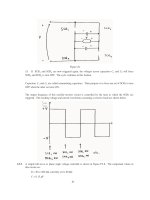
9-7. Plot the torque-speed characteristic of this motor assuming no armature reaction, and again assuming a
full-load armature reaction of 1200 A
⋅
turns.
S
OLUTION
This problem is best solved with MATLAB, since it involves calculating the torque-speed values
at many points. A MATLAB program to calculate and display both torque-speed characteristics is shown
below.
% M-file: prob9_7.m
% M-file to create a plot of the torque-speed curve of the
% the shunt dc motor with and without armature reaction.
% Get the magnetization curve. Note that this curve is
% defined for a speed of 1200 r/min.
load p91_mag.dat
if_values = p91_mag(:,1);
ea_values = p91_mag(:,2);
n_0 = 1200;
% First, initialize the values needed in this program.
v_t = 240; % Terminal voltage (V)
r_f = 100; % Field resistance (ohms)
r_adj = 175; % Adjustable resistance (ohms)
r_a = 0.40; % Armature resistance (ohms)
i_l = 0:1:55; % Line currents (A)
n_f = 2700; % Number of turns on field
218
f_ar0 = 1200; % Armature reaction @ 55 A (A-t/m)
% Calculate the armature current for each load.
i_a = i_l - v_t / (r_f + r_adj);
% Now calculate the internal generated voltage for
% each armature current.
e_a = v_t - i_a * r_a;
% Calculate the armature reaction MMF for each armature
% current.
f_ar = (i_a / 55) * f_ar0;
% Calculate the effective field current with and without
% armature reaction. Ther term i_f_ar is the field current
% with armature reaction, and the term i_f_noar is the
% field current without armature reaction.
i_f_ar = v_t / (r_f + r_adj) - f_ar / n_f;
i_f_noar = v_t / (r_f + r_adj);
% Calculate the resulting internal generated voltage at
% 1200 r/min by interpolating the motor's magnetization
% curve.
e_a0_ar = interp1(if_values,ea_values,i_f_ar);
e_a0_noar = interp1(if_values,ea_values,i_f_noar);
% Calculate the resulting speed from Equation (9-13).
n_ar = ( e_a ./ e_a0_ar ) * n_0;
n_noar = ( e_a ./ e_a0_noar ) * n_0;
% Calculate the induced torque corresponding to each
% speed from Equations (8-55) and (8-56).
t_ind_ar = e_a .* i_a ./ (n_ar * 2 * pi / 60);
t_ind_noar = e_a .* i_a ./ (n_noar * 2 * pi / 60);
% Plot the torque-speed curves
figure(1);
plot(t_ind_noar,n_noar,'b-','LineWidth',2.0);
hold on;
plot(t_ind_ar,n_ar,'k ','LineWidth',2.0);
xlabel('\bf\tau_{ind} (N-m)');
ylabel('\bf\itn_{m} \rm\bf(r/min)');
title ('\bfShunt DC Motor Torque-Speed Characteristic');
legend('No armature reaction','With armature reaction');
axis([ 0 125 800 1250]);
grid on;
hold off;
219
The resulting plot is shown below:
0 20 40 60 80 100 120
800
850
900
950
1000
1050
1100
1150
1200
1250
τ
ind
(N-m)
n
m
(r/min)
Shunt DC Motor Torque-Speed Characteristic
No armature reaction
With armature reaction
For Problems 9-8 and 9-9, the shunt dc motor is reconnected separately excited, as shown in Figure P9-3. It has a
fixed field voltage
V
F
of 240 V and an armature voltage V
A
that can be varied from 120 to 240 V.
Note: Figure P9-3 shows incorrect values for R
A
and R
F
in the first printing of this
book. The correct values are given in the text, but shown incorrectly on the
figure. This will be corrected at the second printing.
9-8. What is the no-load speed of this separately excited motor when
adj
R = 175
Ω
and (a)
A
V = 120 V, (b)
A
V
= 180 V, (c)
A
V = 240 V?
S
OLUTION
At no-load conditions,
AA
EV= . The field current is given by
adj
240 V 240 V
0.873 A
175 100 275
F
F
F
V
I
RR
== ==
+Ω+ΩΩ
From Figure P9-1, this field current would produce an internal generated voltage
Ao
E of 271 V at a speed
o
n of 1200 r/min. Therefore, the speed n with a voltage of 240 V would be
220
A
Ao o
En
En
=
A
o
Ao
E
nn
E
=
(a) If
A
V = 120 V, then
A
E = 120 V, and
()
120 V
1200 r/min 531 r/min
271 V
n
==
(a) If
A
V
= 180 V, then
A
E
= 180 V, and
()
180 V
1200 r/min 797 r/min
271 V
n
==
(a) If
A
V = 240 V, then
A
E = 240 V, and
()
240 V
1200 r/min 1063 r/min
271 V
n
==
9-9.
For the separately excited motor of Problem 9-8:
(a) What is the maximum no-load speed attainable by varying both
A
V
and
adj
R
?
(b) What is the minimum no-load speed attainable by varying both
A
V and
adj
R ?
S
OLUTION
(a) The maximum speed will occur with the maximum
A
V and the maximum
adj
R . The field current
when
adj
R = 400
Ω
is:
adj
240 V 240 V
0.48 A
400 100 500
T
F
F
V
I
RR
== ==
+Ω+ΩΩ
From Figure P9-1, this field current would produce an internal generated voltage
Ao
E
of 199 V at a speed
o
n
of 1200 r/min. At no-load conditions, the maximum internal generated voltage
AA
EV=
= 240 V.
Therefore, the speed n with a voltage of 240 V would be
A
Ao o
En
En
=
()
240 V
1200 r/min 1447 r/min
199 V
A
o
Ao
E
nn
E
== =
(b) The minimum speed will occur with the minimum
A
V and the minimum
adj
R . The field current when
adj
R = 100
Ω
is:
adj
240 V 240 V
1.2 A
100 100 200
T
F
F
V
I
RR
== ==
+Ω+ΩΩ
From Figure P9-1, this field current would produce an internal generated voltage
Ao
E of 287 V at a speed
o
n of 1200 r/min. At no-load conditions, the minimum internal generated voltage
AA
EV= = 120 V.
Therefore, the speed n with a voltage of 120 V would be
221
A
Ao o
En
En
=
()
120 V
1200 r/min 502 r/min
287 V
A
o
Ao
E
nn
E
== =
9-10. If the motor is connected cumulatively compounded as shown in Figure P9-4 and if R
adj
= 175
Ω
, what is
its no-load speed? What is its full-load speed? What is its speed regulation? Calculate and plot the torque-
speed characteristic for this motor. (Neglect armature effects in this problem.)
Note: Figure P9-4 shows incorrect values for R
A
+ R
S
and R
F
in the first printing of
this book. The correct values are given in the text, but shown incorrectly on
the figure. This will be corrected at the second printing.
S
OLUTION
At no-load conditions, 240 V
AT
EV== . The field current is given by
adj
240 V 240 V
0.873 A
175 100 275
F
F
F
V
I
RR
== ==
+Ω+ΩΩ
From Figure P9-1, this field current would produce an internal generated voltage
Ao
E of 271 V at a speed
o
n of 1200 r/min. Therefore, the speed n with a voltage of 240 V would be
A
Ao o
En
En
=
()
240 V
1200 r/min 1063 r/min
271 V
A
o
Ao
E
nn
E
== =
At full load conditions, the armature current is
adj
55 A 0.87 A 54.13 A
T
ALFL
F
V
IIII
RR
=−=− = − =
+
The internal generated voltage
A
E
is
()
()()
240 V 54.13 A 0.44 216.2 V
ATAA S
EVIRR=− + = − Ω=
The equivalent field current is
()
*
SE
27 turns
0.873 A 54.13 A 1.41 A
2700 turns
FF A
F
N
II I
N
=+ = + =
222
From Figure P9-1, this field current would produce an internal generated voltage
Ao
E of 290 V at a speed
o
n of 1200 r/min. Therefore,
()
216.2 V
1200 r/min 895 r/min
290 V
A
o
Ao
E
nn
E
== =
The speed regulation is
nl fl
fl
1063 r/min 895 r/min
SR 100% 100% 18.8%
895 r/min
nn
n
−−
=×= ×=
The torque-speed characteristic can best be plotted with a MATLAB program. An appropriate program is
shown below.
% M-file: prob9_10.m
% M-file to create a plot of the torque-speed curve of the
% a cumulatively compounded dc motor without
% armature reaction.
% Get the magnetization curve. Note that this curve is
% defined for a speed of 1200 r/min.
load p91_mag.dat
if_values = p91_mag(:,1);
ea_values = p91_mag(:,2);
n_0 = 1200;
% First, initialize the values needed in this program.
v_t = 240; % Terminal voltage (V)
r_f = 100; % Field resistance (ohms)
r_adj = 175; % Adjustable resistance (ohms)
r_a = 0.44; % Armature + series resistance (ohms)
i_l = 0:55; % Line currents (A)
n_f = 2700; % Number of turns on shunt field
n_se = 27; % Number of turns on series field
% Calculate the armature current for each load.
i_a = i_l - v_t / (r_f + r_adj);
% Now calculate the internal generated voltage for
% each armature current.
e_a = v_t - i_a * r_a;
% Calculate the effective field current for each armature
% current.
i_f = v_t / (r_f + r_adj) + (n_se / n_f) * i_a;
% Calculate the resulting internal generated voltage at
% 1200 r/min by interpolating the motor's magnetization
% curve.
e_a0 = interp1(if_values,ea_values,i_f);
% Calculate the resulting speed from Equation (9-13).
n = ( e_a ./ e_a0 ) * n_0;
% Calculate the induced torque corresponding to each
% speed from Equations (8-55) and (8-56).
223
t_ind = e_a .* i_a ./ (n * 2 * pi / 60);
% Plot the torque-speed curves
figure(1);
plot(t_ind,n,'b-','LineWidth',2.0);
xlabel('\bf\tau_{ind} (N-m)');
ylabel('\bf\itn_{m} \rm\bf(r/min)');
title ('\bfCumulatively-Compounded DC Motor Torque-Speed
Characteristic');
axis([0 125 800 1250]);
grid on;
The resulting plot is shown below:
Compare this torque-speed curve to that of the shunt motor in Problem 9-7. (Both curves are plotted on the
same scale to facilitate comparison.)
9-11. The motor is connected cumulatively compounded and is operating at full load. What will the new speed of
the motor be if
adj
R
is increased to 250 Ω? How does the new speed compared to the full-load speed
calculated in Problem 9-10?
S
OLUTION
If
adj
R is increased to 250
Ω
, the field current is given by
adj
240 V 240 V
0.686 A
250 100 350
T
F
F
V
I
RR
== ==
+Ω+ΩΩ
At full load conditions, the armature current is
55 A 0.686 A 54.3 A
ALF
III=−= − =
The internal generated voltage
A
E is
()
(
)
(
)
240 V 54.3 A 0.44 216.1 V
ATAA S
EVIRR=− + = − Ω=
224
The equivalent field current is
()
*
SE
27 turns
0.686 A 54.3 A 1.23 A
2700 turns
FF A
F
N
II I
N
=+ = + =
From Figure P9-1, this field current would produce an internal generated voltage
Ao
E of 288 V at a speed
o
n of 1200 r/min. Therefore,
()
216.1 V
1200 r/min 900 r/min
288 V
A
o
Ao
E
nn
E
== =
The new full-load speed is higher than the full-load speed in Problem 9-10.
9-12. The motor is now connected differentially compounded.
(a) If
R
adj
= 175
Ω
, what is the no-load speed of the motor?
(b) What is the motor’s speed when the armature current reaches 20 A? 40 A? 60 A?
(c) Calculate and plot the torque-speed characteristic curve of this motor.
S
OLUTION
(a) At no-load conditions,
240 V
AT
EV==
. The field current is given by
adj
240 V 240 V
0.873 A
175 100 275
F
F
F
V
I
RR
== ==
+Ω+ΩΩ
From Figure P9-1, this field current would produce an internal generated voltage
Ao
E of 271 V at a speed
o
n of 1200 r/min. Therefore, the speed n with a voltage of 240 V would be
A
Ao o
En
En
=
()
240 V
1200 r/min 1063 r/min
271 V
A
o
Ao
E
nn
E
== =
(b) At
A
I = 20A, the internal generated voltage
A
E is
()
()( )
240 V 20 A 0.44 231.2 V
ATAA S
EVIRR=− + = − Ω=
The equivalent field current is
()
*
SE
27 turns
0.873 A 20 A 0.673 A
2700 turns
FF A
F
N
II I
N
=− = − =
From Figure P9-1, this field current would produce an internal generated voltage
Ao
E
of 245 V at a speed
o
n
of 1200 r/min. Therefore,
()
231.2 V
1200 r/min 1132 r/min
245 V
A
o
Ao
E
nn
E
== =
At
A
I = 40A, the internal generated voltage
A
E is
()
()( )
240 V 40 A 0.44 222.4 V
ATAA S
EVIRR=− + = − Ω=
The equivalent field current is
225
()
*
SE
27 turns
0.873 A 40 A 0.473 A
2700 turns
FF A
F
N
II I
N
=− = − =
From Figure P9-1, this field current would produce an internal generated voltage
Ao
E of 197 V at a speed
o
n of 1200 r/min. Therefore,
()
227.4 V
1200 r/min 1385 r/min
197 V
A
o
Ao
E
nn
E
== =
At
A
I
= 60A, the internal generated voltage
A
E
is
()
()( )
240 V 60 A 0.44 213.6 V
ATAA S
EVIRR=− + = − Ω=
The equivalent field current is
()
*
SE
27 turns
0.873 A 60 A 0.273 A
2700 turns
FF A
F
N
II I
N
=− = − =
From Figure P9-1, this field current would produce an internal generated voltage
Ao
E of 121 V at a speed
o
n of 1200 r/min. Therefore,
()
213.6 V
1200 r/min 2118 r/min
121 V
A
o
Ao
E
nn
E
== =
(c) The torque-speed characteristic can best be plotted with a MATLAB program. An appropriate
program is shown below.
% M-file: prob9_12.m
% M-file to create a plot of the torque-speed curve of the
% a differentially compounded dc motor withwithout
% armature reaction.
% Get the magnetization curve. Note that this curve is
% defined for a speed of 1200 r/min.
load p91_mag.dat
if_values = p91_mag(:,1);
ea_values = p91_mag(:,2);
n_0 = 1200;
% First, initialize the values needed in this program.
v_t = 240; % Terminal voltage (V)
r_f = 100; % Field resistance (ohms)
r_adj = 175; % Adjustable resistance (ohms)
r_a = 0.44; % Armature + series resistance (ohms)
i_l = 0:50; % Line currents (A)
n_f = 2700; % Number of turns on shunt field
n_se = 27; % Number of turns on series field
% Calculate the armature current for each load.
i_a = i_l - v_t / (r_f + r_adj);
% Now calculate the internal generated voltage for
% each armature current.
e_a = v_t - i_a * r_a;
% Calculate the effective field current for each armature
226
% current.
i_f = v_t / (r_f + r_adj) - (n_se / n_f) * i_a;
% Calculate the resulting internal generated voltage at
% 1200 r/min by interpolating the motor's magnetization
% curve.
e_a0 = interp1(if_values,ea_values,i_f);
% Calculate the resulting speed from Equation (9-13).
n = ( e_a ./ e_a0 ) * n_0;
% Calculate the induced torque corresponding to each
% speed from Equations (8-55) and (8-56).
t_ind = e_a .* i_a ./ (n * 2 * pi / 60);
% Plot the torque-speed curves
figure(1);
plot(t_ind,n,'b-','LineWidth',2.0);
xlabel('\bf\tau_{ind} (N-m)');
ylabel('\bf\itn_{m} \rm\bf(r/min)');
title ('\bfDifferentially-Compounded DC Motor Torque-Speed
Characteristic');
axis([0 100 800 1600]);
grid on;
The resulting plot is shown below:
Compare this torque-speed curve to that of the shunt motor in Problem 9-7 and the cumulatively-
compounded motor in Problem 9-10. (Note that this plot has a larger vertical scale to accommodate the
speed runaway of the differentially-compounded motor.)
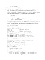
9-13.
A 7.5-hp 120-V series dc motor has an armature resistance of 0.2 Ω and a series field resistance of 0.16 Ω.
At full load, the current input is 58 A, and the rated speed is 1050 r/min. Its magnetization curve is shown
227
in Figure P9-5. The core losses are 200 W, and the mechanical losses are 240 W at full load. Assume that
the mechanical losses vary as the cube of the speed of the motor and that the core losses are constant.
Note: An electronic version of this magnetization curve can be found in file
p95_mag.dat
, which can be used with MATLAB programs. Column 1
contains field current in amps, and column 2 contains the internal generated
voltage E
A
in volts.
(a) What is the efficiency of the motor at full load?
(b) What are the speed and efficiency of the motor if it is operating at an armature current of 35 A?
(c) Plot the torque-speed characteristic for this motor.
S
OLUTION
(a) The output power of this motor at full load is
()( )
OUT
7.5 hp 746 W/hp 5595 WP ==
The input power is
228
()()
IN
120 V 58 A 6960 W
TL
PVI== =
Therefore the efficiency is
OUT
IN
5595 W
100% 100% 80.4%
6960 W
P
P
η
=× = × =
(b) If the armature current is 35 A, then the input power to the motor will be
()()
IN
120 V 35 A 4200 W
TL
PVI== =
The internal generated voltage at this condition is
()
()( )
2
120 V 35 A 0.20 0.16 107.4 V
ATAAS
EVIRR=− + = − Ω+ Ω=
and the internal generated voltage at rated conditions is
()
()( )
1
120 V 58 A 0.20 0.16 99.1 V
ATAAS
EVIRR=− + = − Ω+ Ω=
The final speed is given by the equation
,2 2
222
122,11
Ao
A
AAo
En
EK
EK En
φω
φω
==
since the ratio
,2 ,1
/
Ao Ao
EE is the same as the ratio
21
/
φ
φ
. Therefore, the final speed is
,1
2
21
1,2
Ao
A
AAo
E
E
nn
EE
=
From Figure P9-5, the internal generated voltage
,2Ao
E for a current of 35 A and a speed of
o
n = 1200
r/min is
,2Ao
E = 115 V, and the internal generated voltage
,1Ao
E for a current of 58 A and a speed of
o
n =
1200 r/min is
,1Ao
E
= 134 V.
()
,1
2
21
1,2
107.4 V 134 V
1050 r/min 1326 r/min
99.1 V 115 V
Ao
A
AAo
E
E
nn
EE
== =
The power converted from electrical to mechanical form is
()()
conv
107.4 V 35 A 3759 W
AA
PEI== =
The core losses in the motor are 200 W, and the mechanical losses in the motor are 240 W at a speed of
1050 r/min. The mechanical losses in the motor scale proportionally to the cube of the rotational speedm
so the mechanical losses at 1326 r/min are
() ()
3
3
2
mech
1
1326 r/min
240 W 240 W 483 W
1050 r/min
n
P
n
== =
Therefore, the output power is
OUT conv mech core
3759 W 483 W 200 W 3076 WPPPP=−−= − − =
and the efficiency is
OUT
IN
3076 W
100% 100% 73.2%
4200 W
P
P
η
=× = × =
(c) A MATLAB program to plot the torque-speed characteristic of this motor is shown below:
229
% M-file: prob9_13.m
% M-file to create a plot of the torque-speed curve of the
% the series dc motor in Problem 9-13.
% Get the magnetization curve. Note that this curve is
% defined for a speed of 1200 r/min.
load p95_mag.dat
if_values = p95_mag(:,1);
ea_values = p95_mag(:,2);
n_0 = 1200;
% First, initialize the values needed in this program.
v_t = 120; % Terminal voltage (V)
r_a = 0.36; % Armature + field resistance (ohms)
i_a = 9:1:58; % Armature (line) currents (A)
% Calculate the internal generate voltage e_a.
e_a = v_t - i_a * r_a;
% Calculate the resulting internal generated voltage at
% 1200 r/min by interpolating the motor's magnetization
% curve. Note that the field current is the same as the
% armature current for this motor.
e_a0 = interp1(if_values,ea_values,i_a,'spline');
% Calculate the motor's speed, using the known fact that
% the motor runs at 1050 r/min at a current of 58 A. We
% know that
%
% Ea2 K' phi2 n2 Eao2 n2
% = =
% Ea1 K' phi1 n1 Eao1 n1
%
% Ea2 Eao1
% ==> n2 = n1
% Ea1 Eao2
%
% where Ea0 is the internal generated voltage at 1200 r/min
% for a given field current.
%
% Speed will be calculated by reference to full load speed
% and current.
n1 = 1050; % 1050 r/min at full load
Eao1 = interp1(if_values,ea_values,58,'spline');
Ea1 = v_t - 58 * r_a;
% Get speed
Eao2 = interp1(if_values,ea_values,i_a,'spline');
n = (e_a./Ea1) .* (Eao1 ./ Eao2) * n1;
% Calculate the induced torque corresponding to each
% speed from Equations (8-55) and (8-56).
t_ind = e_a .* i_a ./ (n * 2 * pi / 60);
% Plot the torque-speed curve
230
figure(1);
plot(t_ind,n,'b-','LineWidth',2.0);
hold on;
xlabel('\bf\tau_{ind} (N-m)');
ylabel('\bf\itn_{m} \rm\bf(r/min)');
title ('\bfSeries DC Motor Torque-Speed Characteristic');
grid on;
hold off;
The resulting torque-speed characteristic is shown below:
9-14. A 20-hp 240-V 76-A 900 r/min series motor has a field winding of 33 turns per pole. Its armature
resistance is 0.09
Ω, and its field resistance is 0.06 Ω. The magnetization curve expressed in terms of
magnetomotive force versus E
A
at 900 r/min is given by the following table:
E
A
, V
95 150 188 212 229 243
F, A turns⋅
500 1000 1500 2000 2500 3000
Note: An electronic version of this magnetization curve can be found in file
prob9_14_mag.dat
, which can be used with MATLAB programs. Column
1 contains magnetomotive force in ampere-turns, and column 2 contains the
internal generated voltage E
A
in volts.
Armature reaction is negligible in this machine.
(a) Compute the motor’s torque, speed, and output power at 33, 67, 100, and 133 percent of full-load
armature current. (Neglect rotational losses.)
(b) Plot the terminal characteristic of this machine.
S
OLUTION
Note that this magnetization curve has been stored in a file called
prob9_14_mag.dat
. The
first column of the file is an array of
mmf_values
, and the second column is an array of
ea_values
.
These values are valid at a speed
o
n = 900 r/min. Because the data in the file is relatively sparse, it is
231
important that interpolation be done using smooth curves, so be sure to specify the
'spline'
option in
the MATLAB
interp1
function:
load prob9_14_mag.dat;
mmf_values = prob9_14_mag(:,1);
ea_values = prob9_14_mag(:,2);
Eao = interp1(mmf_values,ea_values,mmf,'spline')
(a) Since full load corresponds to 76 A, this calculation must be performed for armature currents of 25.3
A, 50.7 A, 76 A, and 101.3 A.
If
A
I
= 23.3 A, then
()
()( )
240 V 25.3 A 0.09 0.06 236.2 V
ATAA S
EVIRR=− + = − Ω+ Ω=
The magnetomotive force is
()()
33 turns 25.3 A 835 A turns
A
NI== = ⋅F , which produces a voltage
Ao
E
of 134 V at
o
n
= 900 r/min. Therefore the speed of the motor at these conditions is
()
236.2 V
900 r/min 1586 r/min
134 V
A
o
Ao
E
nn
E
== =
The power converted from electrical to mechanical form is
()()
conv
236.2 V 25.3 A 5976 W
AA
PEI== =
Since the rotational losses are ignored, this is also the output power of the motor. The induced torque is
()
conv
ind
5976 W
36 N m
2 rad 1 min
1586 r/min
1 r 60 s
m
P
τ
π
ω
== =⋅
If
A
I = 50.7 A, then
()
()( )
240 V 50.7 A 0.09 0.06 232.4 V
ATAA S
EVIRR=− + = − Ω+ Ω=
The magnetomotive force is
()()
33 turns 50.7 A 1672 A turns
A
NI== = ⋅F
, which produces a voltage
Ao
E
of 197 V at
o
n = 900 r/min. Therefore the speed of the motor at these conditions is
()
232.4 V
900 r/min 1062 r/min
197 V
A
o
Ao
E
nn
E
== =
The power converted from electrical to mechanical form is
()()
conv
232.4 V 50.7 A 11,780 W
AA
PEI== =
Since the rotational losses are ignored, this is also the output power of the motor. The induced torque is
()
conv
ind
11,780 W
106 N m
2 rad 1 min
1062 r/min
1 r 60 s
m
P
τ
π
ω
== = ⋅
If
A
I = 76 A, then
()
()( )
240 V 76 A 0.09 0.06 228.6 V
ATAA S
EVIRR=− + = − Ω+ Ω=
232
The magnetomotive force is
()()
33 turns 76 A 2508 A turns
A
NI== = ⋅F , which produces a voltage
Ao
E
of 229 V at
o
n = 900 r/min. Therefore the speed of the motor at these conditions is
()
228.6 V
900 r/min 899 r/min
229 V
A
o
Ao
E
nn
E
== =
The power converted from electrical to mechanical form is
()()
conv
228.6 V 76 A 17,370 W
AA
PEI== =
Since the rotational losses are ignored, this is also the output power of the motor. The induced torque is
()
conv
ind
17,370 W
185 N m
2 rad 1 min
899 r/min
1 r 60 s
m
P
τ
π
ω
== = ⋅
If
A
I
= 101.3 A, then
()
()( )
240 V 101.3 A 0.09 0.06 224.8 V
ATAA S
EVIRR=− + = − Ω+ Ω=
The magnetomotive force is
()()
33 turns 101.3 A 3343 A turns
A
NI== = ⋅F , which produces a voltage
Ao
E
of 252 V at
o
n
= 900 r/min. Therefore the speed of the motor at these conditions is
()
224.8 V
900 r/min 803 r/min
252 V
A
o
Ao
E
nn
E
== =
The power converted from electrical to mechanical form is
()()
conv
224.8 V 101.3 A 22,770 W
AA
PEI== =
Since the rotational losses are ignored, this is also the output power of the motor. The induced torque is
()
conv
ind
22,770 W
271 N m
2 rad 1 min
803 r/min
1 r 60 s
m
P
τ
π
ω
== = ⋅
(b) A MATLAB program to plot the torque-speed characteristic of this motor is shown below:
% M-file: series_ts_curve.m
% M-file to create a plot of the torque-speed curve of the
% the series dc motor in Problem 9-14.
% Get the magnetization curve. Note that this curve is
% defined for a speed of 900 r/min.
load prob9_14_mag.dat
mmf_values = prob9_14_mag(:,1);
ea_values = prob9_14_mag(:,2);
n_0 = 900;
% First, initialize the values needed in this program.
v_t = 240; % Terminal voltage (V)
r_a = 0.15; % Armature + field resistance (ohms)
i_a = 15:1:76; % Armature (line) currents (A)
n_s = 33; % Number of series turns on field
% Calculate the MMF for each load
233
f = n_s * i_a;
% Calculate the internal generate voltage e_a.
e_a = v_t - i_a * r_a;
% Calculate the resulting internal generated voltage at
% 900 r/min by interpolating the motor's magnetization
% curve. Specify cubic spline interpolation to provide
% good results with this sparse magnetization curve.
e_a0 = interp1(mmf_values,ea_values,f,'spline');
% Calculate the motor's speed from Equation (9-13).
n = (e_a ./ e_a0) * n_0;
% Calculate the induced torque corresponding to each
% speed from Equations (8-55) and (8-56).
t_ind = e_a .* i_a ./ (n * 2 * pi / 60);
% Plot the torque-speed curve
figure(1);
plot(t_ind,n,'b-','LineWidth',2.0);
hold on;
xlabel('\bf\tau_{ind} (N-m)');
ylabel('\bf\itn_{m} \rm\bf(r/min)');
title ('\bfSeries DC Motor Torque-Speed Characteristic');
%axis([ 0 700 0 5000]);
grid on;
hold off;
The resulting torque-speed characteristic is shown below:
9-15. A 300-hp 440-V 560-A, 863 r/min shunt dc motor has been tested, and the following data were taken:
Blocked-rotor test:
234
V
A
= 163. V exclusive of brushes V
F
= 440 V
I
A
= 500 A I
F
= 886. A
No-load operation:
V
A
= 163. V including brushes
I
F
= 876. A
I
A
= 231. A
r/min 863=n
What is this motor’s efficiency at the rated conditions? [Note: Assume that (1) the brush voltage drop is 2
V; (2) the core loss is to be determined at an armature voltage equal to the armature voltage under full load;
and (3) stray load losses are 1 percent of full load.]
S
OLUTION
The armature resistance of this motor is
,br
,br
16.3 V
0.0326
500 A
A
A
A
V
R
I
== = Ω
Under no-load conditions, the core and mechanical losses taken together (that is, the rotational losses) of
this motor are equal to the product of the internal generated voltage
A
E and the armature current
A
I , since
this is no output power from the motor at no-load conditions. Therefore, the rotational losses at rated speed
can be found as
()( )
brush
442 V 2 V 23.1 A 0.0326 439.2 V
AA AA
EVV IR=− − = − − Ω=
()()
rot conv
439.2 V 23.1 A 10.15 kW
AA
PP EI== = =
The input power to the motor at full load is
()()
IN
440 V 560 A 246.4 kW
TL
PVI== =
The output power from the motor at full load is
OUT IN CU rot brush stray
PPPPPP=−−− −
The copper losses are
()( )()( )
2
2
CU
560 A 0.0326 440 V 8.86 A 14.1 kW
AA FF
PIRVI=+= Ω+ =
The brush losses are
()( )
brush brush
2 V 560 A 1120 W
A
PVI== =
Therefore,
OUT IN CU rot brush stray
PPPPPP=−−− −
OUT
246.4 kW 14.1 kW 10.15 kW 1.12 kW 2.46 kW 218.6 kWP =−− −−=
The motor’s efficiency at full load is
OUT
IN
218.6 kW
100% 100% 88.7%
246.4 kW
P
P
η
=× = × =
Problems 9-16 to 9-19 refer to a 240-V 100-A dc motor which has both shunt and series windings. Its
characteristics are
R
A
= 0.14 Ω
N
F
= 1500 turns
R
S
= 0.04 Ω
N
SE
= 12 turns
235
R
F
= 200
Ω
n
m
= 1200 r/min
R
adj
= 0 to 300
Ω
, currently set to 120
Ω
This motor has compensating windings and interpoles. The magnetization curve for this motor at 1200 r/min is
shown in Figure P9-6.
Note: An electronic version of this magnetization curve can be found in file
p96_mag.dat, which can be used with MATLAB programs. Column 1
contains field current in amps, and column 2 contains the internal generated
voltage E
A
in volts.
9-16. The motor described above is connected in shunt.
(a) What is the no-load speed of this motor when
R
adj
= 120 Ω?
(b) What is its full-load speed?
(c) Under no-load conditions, what range of possible speeds can be achieved by adjusting
R
adj
?
S
OLUTION
Note that this magnetization curve has been stored in a file called p96_mag.dat. The first
column of the file is an array of
ia_values
, and the second column is an array of
ea_values
. These
values are valid at a speed
o
n = 1200 r/min. These values can be used with the MATLAB
interp1
function to look up an internal generated voltage as follows:
load
p96_mag.dat;
236
if_values = p96_mag(:,1);
ea_values =
p96_mag(:,2);
Ea = interp1(if_values,ea_values,if,'spline')
(a) If
adj
R = 120
Ω
, the total field resistance is 320
Ω
, and the resulting field current is
adj
240 V
0.75 A
200 120
T
F
F
V
I
RR
== =
+Ω+Ω
This field current would produce a voltage
Ao
E of 256 V at a speed of
o
n = 1200 r/min. The actual
A
E is
240 V, so the actual speed will be
()
240 V
1200 r/min 1125 r/min
256 V
A
o
Ao
E
nn
E
== =
(b) At full load, 100 A 0.75 A 99.25 A
ALF
III=−= − = , and
()()
240 V 99.25 A 0.14 226.1 V
ATAA
EVIR=− = − Ω=
Therefore, the speed at full load will be
()
226.1 V
1200 r/min 1060 r/min
256 V
A
o
Ao
E
nn
E
== =
(c) If
adj
R is maximum at no-load conditions, the total resistance is 500
Ω
, and
adj
240 V
0.48 A
200 300
T
F
F
V
I
RR
== =
+Ω+Ω
This field current would produce a voltage
Ao
E of 200 V at a speed of
o
n
= 1200 r/min. The actual
A
E is
240 V, so the actual speed will be
()
240 V
1200 r/min 1440 r/min
200 V
A
o
Ao
E
nn
E
== =
If
R
adj
is minimum at no-load conditions, the total resistance is 200
Ω
, and
adj
240 V
1.2 A
200 0
T
F
F
V
I
RR
== =
+Ω+Ω
This field current would produce a voltage
Ao
E of 287 V at a speed of
o
n = 1200 r/min. The actual
A
E is
240 V, so the actual speed will be
()
240 V
1200 r/min 1004 r/min
287 V
A
o
Ao
E
nn
E
== =
9-17. This machine is now connected as a cumulatively compounded dc motor with
adj
R = 120
Ω
.
(a) What is the full-load speed of this motor?
(b) Plot the torque-speed characteristic for this motor.
(c) What is its speed regulation?
S
OLUTION