Drilling and Associated Cutting Tool Technology Industrial Handbook_5 potx
Bạn đang xem bản rút gọn của tài liệu. Xem và tải ngay bản đầy đủ của tài liệu tại đây (866.01 KB, 9 trang )
e insert’s substrate – if cemented carbide – re-
quires some thought, as if it is too hard, this type of
insert may chip via the eects of machining vibrations,
this is particularly so, if the tool geometry has an ex-
tra-positive and sharp insert cutting edge. It might be
more prudent to initially choose a medium-hard ce-
mented carbide grade, as it tends to cope with a poten-
tial edge-chipping condition more readily, then, if this
proves successful, a harder grade may be selected.
Cutting Parameters – Decisions
Two complementary cutting parameters are the insert’s
nose radius and the inuence it has on the D
OC
. For
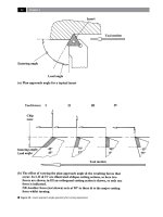
Figure 62. Interchangeable cutting heads for machining internal features. [Courtesy of Sandvik Coromant].
Drilling and Associated Technologies
example, when a nish boring operation is required,
then it is recommended that both a small nose radius
and D
OC
is used. is smaller boring insert nose ra-
dius, minimises contact between the workpiece and
insert, resulting in lower tangential and radial cutting
forces. For ne-boring applications, a good start point
is to choose an insert with a 0.4 mm nose radius, with
a 0.5 mm D
OC
. It should be noted that the D
OC
ought to
be larger than the nose radius, this is because if it was
the other way around, cutting forces would be directed
in a radial direction – increasing potential vibrational/
bar-bending (i.e. push-o
42
) problems.
Feedrates should be identical regardless of tool’s
overhang, as any feed selection is normally based upon
the insert’s chip-breaking capabilities. Avoidance of
very high feedrates when rough boring is necessary, as
it can signicantly increase the tangential cutting force
component. For nish boring operations, it is normally
the workpiece’s surface texture requirement that dic-
tates the maximum feedrate that can be utilised. More
will be mentioned on the machined cusp height’s eect
on surface texture, this being created by the remnants
of the partial nose arc (i.e. radius) of the cutting insert
and the periodic nature of the selected feedrate on the
bored workpiece’s surface, later on in the relevant sec-
tion in the book.
A mistake oen made by setters/machinists in
order to attempt to
minimise vibrational tendencies, is
to reduce the rpm. is strategy will not only decrease
productivity, but the lower rotational speed can lead
to BUE formation, which in turn, modies the insert’s
cutting geometry and could change the cutting force
directions. Instead of rpm reductions, modication
of other cutting data variables is suggested, in order
to improve these adverse vibrational/chatter eects.
Sometimes even increasing the rotational speed, can
eliminate unwanted chatter.
Although it is not a specic cutting performance
parameter, an oen disregarded measure is that of
boring bar tool clamping. In many circumstances, cy-
lindrical boring bars are simply clamped with several
setscrews, this is a poor choice of clamping method, as
at best, setscrews only contact about 10% of the boring
bar. Conversely, a split-tool block, clamps along almost
42 ‘Tool push-o ’ – oen termed ‘spring-cuts’ , are the result of
tool deection, particularly when light cuts are used. To mini-
mise the ‘push-o’ , very rigid workpiece-machine-tool setup
with a smaller nose radius to that of the D
OC
is recommended.
all of the boring bar’s periphery in the toolpost, allow-
ing much greater tool rigidity and cutting stability, al-
leviating many of the potential problematic in-service
machining conditions.
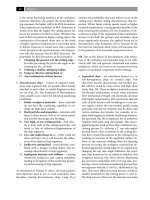
.. Multiple-Boring Tools
Twin cutting insert tooling, usually consists of a cy-
lindrical shank with slides mounted at the front (Fig.
63a), or a U-shaped bar with cartridges (Fig. 63b). e
slides and cartridges can be radially adjusted, allow-
ing for a range of various bored diameters to be ma-
chined. Normally, such tooling has a 7 mm maximum
cutting depth recommended – for both edges simul-
taneously in-cut. With Twin-edged boring tools the
cartridges can be so arranged, that ‘Step-boring’
43
can
be utilised.
When large diameter component features require
a boring operation, then the ‘Divided-version boring’
tooling can be exploited, but diametral accuracy is not
as good as for some of the other types of boring tool
designs. An advantage of the Divided-version’ boring
tools, is the fact that a large diameter range can be cov-
ered, with this single tool. If a ‘Universal ne-boring’
tool is utilised (Fig. 63b), either internal (Fig. 63b-top),
or external machining (Fig. 63b – bottom), can be un-
dertaken. In this case, the ne-bore cartridges (1) are
mounted on a radially-moveable slide (2), which is
mounted on a bar (3). In the latter case of external com-
ponent feature boring, there is a physical limit to the
minimum diameter that can be machined – this being
controlled by the bar’s actual size. (i.e. Here, it should be
said that this particular tooling ‘setup’ can be thought
of as virtually a Trepanning operation with a boring
tool). Moreover, with this external nishing operation,
the spindle must rotate in a le-hand rotation.
Tri-bore tooling oen having individual micro-bore
cartridge adjustment (i.e. not shown), as its name im-
plies, uses three cutting inserts equally-spaced at 120°
apart. is boring tool arrangement of cutting inserts,
oers very high quality bored diametral accuracy and
43 ‘Step-boring’ , refers to using special shims with one of the
cutting inserts axially situated a little way in front of the other,
while at the same time, the cartridges are radially adjusted en-
abling the front insert to cut a slightly smaller diameter to that
of the rear one. It should be noted that when ‘Step-boring’ , the
maximum D
OC
is normally 14 mm, with an associated feedrate
of 0.2 mm rev
–1
.
Chapter
Figure 63. Twin-edged boring tooling. [Courtesy of Sandvik Coromant].
Drilling and Associated Technologies
precision to the machined hole, but such tooling can
be somewhat more costly than when utilising a single-
insert tool.
.. Boring Bar Damping
For boring bars that have an L/D ratio of <5:1, then
relatively stable cutting conditions with controllable
vibrational inuences can be tolerated. However, if L/D
ratios utilised are larger than this limiting value, then
potentially disastrous vibrational tendencies could oc-
cur, leading to a variety of unwanted machining and
workpiece characteristics, these include:
•
Limited tool life – caused by forced and self-excited
vibrations, restricting both cutting eciency and
tool life,
•
Unacceptable machined surface texture – vibra-
tions in the form of workpiece surface chatter, can
be the cause for component rejection,
•
Substandard machined roundness – vibration/
chatter eects creating high-frequency harmonic
44
eects on the roundness prole.
Stiness can be expressed in terms of either static, or
dynamic stiness. Static stiness of a bar is its ability to
resist a bending force in a static condition, conversely,
dynamic stiness is the bar’s ability to withstand os-
cillating forces (i.e. vibrations). Dynamic stiness is an
essential property for a boring bar, as it is a measure of
its capacity to dampen the vibrations occurring during
machining, being greatly dependent of its overhang. As
one would expect in testing for dynamic stiness, with
44 ‘Harmonics’ – on a machined component are the product
of complex interactions, including method of manufacture:
component geometry, cutting data utilised, any vibrational
inuences encountered and material composition and its
manufacture (e.g. Powder Metallurgy parts can vary in both
porosity and density throughout the part, which may aect, or
locally destabilised the cutting edge).
NB Harmonics on the machined workpiece, can be thought
of as a uniform waveform (i.e. sinewave) that is superim-
posed onto the part’s surface. e part’s low frequency harmo-
nicoen has higher frequency harmonics superimposed onto
the roundness. For example, a 15 undulation per revolution
(upr) harmonic, could have a 500 upr harmonic superimposed
onto it, requiring suitable a Roundness Testing Machine with
Gaussian lters to separate out the respective harmonic con-
ditions – for metrological inspection and further analysis.
a boring bar’s overhang increasing under standardised
machining conditions, the amplitude will also increase.
However, if the boring bar was dampened in some
way, perhaps by utilising a ‘shock-absorber eect’ , ma
-
chining could be undertaken at longer overhangs. is
‘damping eect’ is indicated by the highly centralised
amplitude of oscillatory movements quickly reducing
with time, indicating a high level of dynamic stiness,
this being crucial for long L/D ratios. Obviously, the
boring bar’s cutting edge deection at its tool tip, is
directly related to the amount of bar overhang, this de-
ection being the result of the applied cutting forces.
e magnitude of a boring bar’s deection being de-
pendent upon: bar composition, diameter, overhang
and the extent and magnitude of tangential and radial
cutting forces. e rigidly clamped and cantilevered
boring bar’s ‘free-end’ will deect/deform by forces
acting upon it and, some idea of the magnitude of this
deection can be gleaned by the simple application of
‘mechanics of materials’ , using the following formula:
F L
E I
(mm)
Where:
∆ = Boring bar deection (mm),
F = Cutting force (N),
L = Boring bar overhang (mm),
E = Bar material’s coecient of elasticity (N mm
–2
),
*I = Moment of Inertia (mm
4
).
* For a boring bar of circular cross-section, the Mo-
ment of inertia will be:
I = π × D
4
/64 (mm
4
).
For example, assuming that if a φ25 mm steel boring
bar has an L/D overhang of 4:1, with an applied cut-
ting force of 100 kP, then the magnitude of bar deec-
tion, using the above formula, would be:
∆
L = 4D
= 0.083 mm.
If the overhang of this boring bar was now increased
to L/D ratios of 7:1 and 10:1, respectively, this would
produce tool tip deections of:
∆
L = 7D
= 0.444 mm
∆
L = 10D
= 1.293 mm.
Hence, these deection values emphasise the impor-
tance of reducing overhang as it increases by approxi-
mately ‘cube’ of the distance. Moreover, deection can
Chapter
also be reduced by utilising a dierent boring bar ma-
terial, as this will improve its coecient of elasticity
45
.
In boring-out roughing operations, any vibrations
present are only a problem if they lead to insert dam-
age. For nish-boring operations, vibrational condi-
tions that may occur could be the dierence between
success and failure for the nished machined part.
So, the boring bar’s ability to dampen any vibrational
source becomes imperative, once a ne-boring opera-
tion is necessary. Vibrations can occur in any number
of ways that could aect the boring operation, from
the constructional elements of the machine tool,
through to slideways, or their recirculating ball bear-
ings, etc Hence, the joints in a machine tool can be
regarded as a complicated dynamic system, with any
slideway motion of vibrating contact faces, necessitat-
ing lubricating oil to not only reduce any stiction and
frictional eects, but to help dampen these structural
elements. Machine tool builders are acutely aware that
certain machine tool materials ‘damp’ more readily
than others. Cast iron and in particular ‘Granitan’ (i.e.
a product of crushed granite and epoxy resin), can pre-
dominantly act as built-in dampening media for any
vibrational sources present. e main source for any
vibrations in boring, results from the long overhangs,
necessary to machine the hole depth of the compo-
nent’s feature. erefore, the magnitude of vibrations
in the overall system result from the dampening capa-
bilities of the actual boring bar.
Tuned Boring Bars
A boring bar that has been ‘tuned’ , has the ability to
dampen any generated vibrations between the work-
piece and the cutting edge while machining. e
‘dampening eect’ is achieved through a vibration ab-
sorbing device (i.e see Figs. 61a and 62b), this has the
consequence of increasing the bar’s dynamic stiness,
giving it the ability to withstand oscillating forces. e
45 Coecient of elasticity, for a steel boring bar composition,
E = 21 × 10
4
(N mm
–2
), conversely, using a cemented carbide
material for an identical boring bar, E = 63 × 10
4
(N mm
–2
), giv-
ing three times greater stiness, allowing much greater boring
bar overhangs.
NB In reality, the boring bar’s deection will be higher than
the values given in these examples, as the formula is based
upon the assumption that the bar is absolutely rigidly clamped,
which is impossible to achieve.
method of achieving this bar damping has already been
mentioned in Section 3.2.1, with the relationships be-
tween the size of the bar’s body, suspension, viscosity
of the liquid media, being carefully designed by the
tooling manufacturer. During the boring operation,
the vibrations set the body in oscillation. Hence, the
body and the liquid alternate, taking each others place
in the space within the actual boring bar. A pattern is
established during boring, where the oscillations of the
body are not in harmony with the vibrations resulting
from machining. is out-of-harmony, means that the
vibrations are virtually neutralised – to an acceptable
level – via the kinetic energy being transformed by the
‘system damping’. Any vibrations present during bor-
ing, are relative to the amount of bar overhang, there-
fore on longer boring bar lengths, they are normally
tted with some means of adjustment, so that they can
be ‘tuned’ to the frequency occurring within its range.
e simplest manner of achieving adjustment, is by
a rotation of a lockable set screw, which when either
tightened, or slackened, aects the suspension of the
body in the liquid, thus ‘tuning’ the boring bar to the
actual machining conditions present.
.. ‘Active-suppression’
of Vibrations
As has been stated at the beginning of Section 3.2.4, if
boring bars have an L/D ratio >5:1, then vibrational ef-
fects may result in tool chatter. It has been observed in
experimental work, that the boring bar’s tip produces
a vibration motion that follows an elliptical path in the
plane normal to the longitudinal axis of the bar. e
ratio of the amplitude of vibration along the major and
minor axes varies with cutting conditions, further-
more, the inclination of these axes to the ‘radial line’
of the tool also varies. Of signicance, is the fact that
the build-up of chatter will begin almost immediately,
even before one revolution of the workpiece has oc-
curred. is build-up continues almost evenly until
some limiting amplitude occurs, which suggests that
the well-known ‘Orthogonal mode coupling’ is pres-
ent, further, with the phase dierence between the vi-
brations causing an elliptical tool tip path, the vibra-
tional energy is fed into the tool-workpiece system,
promoting self-excitation.
As has been suggested, the dynamic stability of the
boring bar is of prime importance, with the onset of
self-excited chatter, being governed by the ‘Multiple
regenerative eect’ , which is a function of the so-called
Drilling and Associated Technologies
‘space phase’. is ‘space phase’ condition, is the phase
of vibration around respective turns of work, uctu-
ating between 90° and 180° and is equal to the phase
between the inner and outer modulation. Moreover,
it has been shown that by modifying the workpiece’s
rotational speed, this disturbs the ‘space phase’ and,
consequently inuences the ‘time phase’ , leading to
a reduction in self-excited chatter. It has been practi-
cally demonstrated that by modifying the peripheral
speed of the workpiece, this technique is only partially
successful in alleviating chatter. More success can be
made by utilising damped boring bars, such as the
‘Lanchester’ type
46
, with dynamic vibration absorbers
(DVA’s), to really suppress vibrational inuences dur-
ing the boring process.
Some progress has been made on the development
of DVA techniques, but the potential ‘step-change’
will occur in vibrational suppression for boring bars,
when the improvement of production versions of ‘ac-
tive’ dampers for such tooling becomes a reality. Just
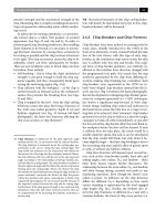
such a potential ‘active’ boring bar is shown schemati-
cally in Fig. 64. Invariably, the boring bar has a supply
of energy to it – via an external source, that controls
the cutting edge’s position by monitoring the feedback
of the relative displacement of tool’s edge with respect
to the workpiece. In later research work by Matsubara
et al. (1987), chatter suppression was analysed for the
boring bar using ‘feed-forward’ control of the cutting
force. Further, the cutting edge was positioned in re-
sponse to this force, with these type of ‘active’ control
systems being known as: ‘Cutting edge positional con-
trol systems’.
Typical of a vibrational control approach is illus-
trated by the ‘active’ boring bar already mentioned and
depicted in Fig. 64, where the forces are damped in re-
sponse to the vibrational velocity of the cutting edge,
which has been termed a: ‘Vibrational velocity control
system’. In this damping technique, the boring bar sup-
pression is by a series of piezo-electric elements that
act as ‘active dampers’. Such a ‘damper’ responds to
onset of chatter vibration (i.e. the high-energy com-
ponents). Moreover, the damping force achieves opti-
mal phase dierence, since the phases between both
46 ‘Lanchester boring bars’ , normally utilise an internal metal
slug which is usually surrounded by some form of: liquid/uid
medium, DVA’s, or more primitively, sprung-loaded and as
such, the slug is free to move out-of-phase with the cutting
conditions, dictated by the boring bar’s applied cutting forces,
thereby the onset of chatter will be potentially ‘cancelled out’.
the ‘damping’ and vibrational forces are controllable.
is type of ‘active’ boring bar arrangement, achieves
directional damping characteristics via its ‘dampers’ ,
here they control two ‘degrees of freedom’
47
via the ‘Re-
generative feedback loop’ , which diminishes oscillatory
motion (i.e. harmonics), by careful control of energy
losses.
In recent years with the advent of articial intelli-
gence (AI) applications to major industrial engineering
problems, and more specically, in the performance
and robustness of certain types of ‘Neural networks’ ,
the goal of obtaining some form of real-time monitor-
ing and control in the machining process is now closer
to reality. ese AI systems have been successfully
utilised for applied research applications to tool wear
monitoring in turning tool operations – aer suitable
‘training’ of a pre-selected neural network architecture.
ese ‘networks’ could be successfully applied to bor-
ing bar vibrational monitoring and control situations.
More detailed information will be said on how, where
and when Neural network decision-making and, why
these cutting tool monitoring applications should be
utilised in the production environment, later in the
text.
.. Hard-part Machining,
Using Boring Bars
Although ‘hard-part’ turning has been utilised for
some considerable time, with the advent of polycrys-
talline cubic boron nitride (PCBN) tooling, etc., it has
seen little in the way of exploitation for boring opera-
tions, to date. One of the major reasons for this lack
of tooling application, is because most hardened parts
are in the region of hardness values ranging from 42
to 66 HR
C
. Such high component hardness, requires
considerable shearing capability by the tooling to suc-
cessfully machine the excess stock from the workpiece.
Generally, the robust nature of toolholding for turning
47 ‘Degrees of Freedom’ , the ‘free-body kinematics’ , exhibit 6 de-
grees of translatory (i.e. linear) motions in space, these are: back-
ward/forward, upward/downward and leward/rightward.
NB Of some interest but in the main, to machine tool build-
ers for the purposes of volumetric calibration, are the rotary
motions of: yaw, pitch and roll, giving 18 degrees of freedom,
together with the 3 squareness errors, totalling 21 possible de-
grees of freedom.
Chapter
Figure 64. An ‘active’ boring bar and their capacity to suppress vibrational eects on boring holes [After. Mat-
subara; Yamamoto and Mizumoto; 1987]
.
Drilling and Associated Technologies
tools with their modest overhangs, does not present in-
surmountable diculties during machining, however
for the much longer overhangs associated with boring
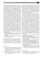
operations (i.e. see Figs. 62a and 65a), then the cutting
forces generally dictate, short L/D ratios of <5:1 and
relatively large and robust boring bars (Fig. 65b).
ere are considerable diculties to be over-
come when any form of hard-part machining is
required – particularly for boring operations, when
the components have been either case- or through-
hardened, these are:
•
High temperatures in the cutting zone – necessitat-
ing high temperature resistant and thermally-sta-
bility of cutting insert materials,
•
Cutting force magnitudes are both higher and more
variable – robust cutting edge geometry is neces-
sary to withstand these increased shearing/cutting
force demands on the insert,
•
Small chip cross sections – these exert high pres-
sure near the insert’s cutting edge, oen necessitat-
ing an edge preparation to the insert’s corner,
•
Greater tool wear rates – oen more rapid cutting
edge wear, or the tendency to catastrophic break-
down of the insert,
•
Workpiece stresses during cutting – these stresses
are released during machining and may present
localised geometric variations to the nal shape of
the part,
•
Poor homogeneity in the workpiece material
– hardness variations across and through the part
(e.g. dierential case hardened depths), can lead to
signicant and variable cutting force loadings on
the boring insert,
•
Insucient stability – if the ‘machine-tool-work-
piece loop’ is not suciently robust, then due to the
greater cutting forces when hard-part machining,
Figure 65. Boring bar operational limitations and hard part boring at relatively high speed. [Cour-
tesy of Sandvik Coromant]
.
Chapter
this creates potential tool deection which could
become a major problem.
Boring Bar Deflection
When any boring operations take place, even with a
very rigid tool mounting and a small boring bar over-
hang, some vibration and tool tip deection will in-
evitably occur, this is exacerbated by machining hard-
parts. e former problem of vibration has previously
been mentioned and methods of minimising it are
possible. However, tool deections are more dicult,
if not impossible to completely eliminate, with these
longer cantilevered tools. Of note regarding overhang-
ing tool deections, are that a tool tip deects in two
directions (i.e. see Fig. 66a), these are:
•
Radial deection (∆
T
) – aects the machined (i.e.
bored) diameter,
•
Tangential deection (∆
R
) – causes the tip to move
downward for the centreline.
In each of these tool tip deections, both the size and
direction of the cutting forces are inuenced by the
chip thickness and insert geometry selected (i.e. illus-
trated in Fig. 66b). e radial deection will be equal
to the dierence between the diameter which was orig-
inally set and the actual bored diameter, this can be
easily found by the simple expedient of measuring it,
then adjustment can be made for this apparent deec-
tion. e tangential deection of the boring bar’s tip
can be established by either ‘direct’ , or ‘indirect’ met
-
rological techniques at the tool’s tip. In Fig. 66a, the
graph depicts deections ‘∆’ (i.e. both the tangential
‘∆
T
’ and radial deection ‘∆
R
’), as a function of the
cutting depth ‘a
P
’. Due to the fact that the tangential
deection (∆
T
) linearly increases with increasing D
OC
(a
P
), it is usually recommended that machining passes
are divided into a number of cuts when close toler-
ances are needed (i.e. in the region of IT7
48
) – see Table
5
49
for an abridged version of the IT tolerances, with
*Rmax values in µm.
e magnitude of radial deection as a function
of the cutting depth, is also inuenced by the ratio
between the insert’s nose radius and the D
OC
(a
P
), to-
gether with the boring insert’s entering angle. In some
cases, a boring bar is situated slightly above the work-
piece centreline, so that when it enters the cut at full
depth it will have tangentially-deected to the actual
48 ‘IT’ (i.e. in units of µm) – represents the average value of the
basic tolerance for the ‘diameter range’ in question. Hence, it
will vary according to the choice of diameter range selected.
49 ese values are related to surface texture expression of:
*Rmax (µm), which is: e maximum individual peak-to-val-
ley height. e Rmax values (i.e. in Table 5) can be calculated
from the IT value, using the following equation, rather than
the conventional equation: Rmax = (fn
2
/r
ε
) 125
this equation tends to give excessively high surface texture va-
lues, thus more practical values related to IT are to be found
from:
�
Rmax
IT
n IT
(µm)
Where: n = e number of IT’s.
Table 5:
IT values related to the basic tolerance for various diameter ranges
Dc (mm): Over /up to
-/3
Over/up to
3/10
Over/up to
10/50
Over/up to
50/180
Over/up to
180/400
Over/up to
400/800
IT5 0.6 0.8 1.3 2.2 3.2 4.5
IT6 0.9 1.2 1.9 3.1 4.6 6.4
IT7 1.4 1.9 3.1 5.0 7.4 10.1
IT8 2.0 2.9 4.7 7.8 11.5 15.8
IT9 3.6 7.5 9.4 12.4 18.3 25.2
IT10 5.7 7.6 12.1 20.0 29.8 40.5
IT11 8.6 11.8 19.1 31.4 46.2 63.8
[Source: Sandvik Coromant (1995)]
.
Drilling and Associated Technologies