Machining of High Strength Steels With Emphasis on Surface Integrity by air force machinability data center_11 pot
Bạn đang xem bản rút gọn của tài liệu. Xem và tải ngay bản đầy đủ của tài liệu tại đây (635.08 KB, 9 trang )
the machining operation, but it also provides the user
with validated and relevant data analysis. ese posi-
tive benets enable tool designers and users alike, to
design and develop advanced cutting tools and to un-
dertake ecient and optimised machining operations.
Beyond the positive advantages of tool optimisation,
simulation can signicantly reduce tooling develop-
ment costs and lead times to bring a newly-developed
product to market. e role of machining simulation
is likely to rapidly grow, as more tooling and produc-
tion engineers become aquainted with these soware
packages.
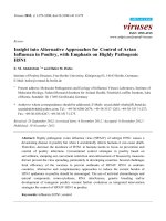
Figure 184. The insert’s cutting edge: illustrating the ‘rounding eect’ (exaggerated) or, a manufacturer’s ‘edge preparation’ and
the material ow conditions that arise as a result
.
Machinability and Surface Integrity
7.10 Surface Integrity of
Machined Components –
Introduction
Previously in Section 7.5 concerning machined sur-
face texture, the discussion was principally concerned
with the resultant surface topography where the topo-
graphical information was valid, but disguised the fact
that potential sub-surface material layers might have
compromised and altered the machined component.
e concept of the overall functional performance of
a surface and its accompanying sub-surface condition
was recognised by Field and Kahles (1971), where they
used the term ‘Surface Integrity’ to describe its poten-
tial state. e overall concept of surface integrity ant
its various generating mechanisms in conjunction with
the production process is known as the ‘unit event’
81
.
is unit event has now been reclassied into ve
discrete generating mechanisms: chemical, mechani-
cal, mechano-thermal, thermo-mechanical and ther-
mal – the order they are listed reects their respective
power density per unit area. For example, increases in
the power density from the chemical end of the series,
results in an augmented level of thermal energy enter-
ing the surface leading to greater thermal damage and
poorer part surface integrity. e chemical mechanism
is dominant across all classes of production process to
some degree and that surfaces react with their imme-
diate environment, via absorbates, oxidation, etc., as
illustrated in Fig. 185 – more will be said on these ef-
81 ‘Unit event’ , is a complex interrelated series of reactions with
the potential for distinct zones to be present within the sur-
face vicinity, including a:
Chemically aected layer (CAL) – resulting from chemical
surface changes by the production process, or from post-
production exposure to a local environment,
Mechanically aected layer (MAL) – this may be due to
factors such as material bulk transportation: deposits; laps;
folds and plastic deformation,
Heat aected layer (HAL) – principally concerned with
factors such as: phase transformation; thermal cracking and
retempering,
Stress aected layer (SAL) – is in the main, the result of
residual stresses being a combination of the above. (Field
and Kahles, 1971)
–
–
–
–
fects when discussing the machined surface condition
in the following section.
.. Residual Stresses
in Machined Surfaces
A machined surface is the product of either ‘abusive’ ,
or ‘gentle’ machining regimes, these being the direct
result of the cutting process and its chosen machining
data. us, machining being a complex relationship of
many interrealated factors, aects the outcome of the
production process – see Fig. 144. Here, a simplistic
schematic diagram attempts to show the complexity
of a machining operation, with the surface integrity
grouping indicating for a turning operation the fol-
lowing features:
•
Surface condition – surface texture and its associ-
ated roundness,
•
Micro-structural changes – micro-cracks, disloca-
tions and ssures, etc.,
•
Surface displacement – bulk transportation of ma-
terial and residual stresses,
•
Surface/sub-surface micro hardness – plastic de-
formation and localised residual stress layers.
Machined surfaces are even more complex than seem-
ingly at rst glance, as their performance can be in-
uenced by either external layers (chemical transfor-
mations and plastic deformations) and internal layers
(metallurgical transformations and residual stresses).
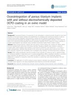
By way of example, the anisotropic – periodic
– longitudinally turned surface illustrated in Fig. 185,
is aected by the cutting insert’s tool tip geometry
and the regularity of the cusps (i.e. peaks and val-
leys) – the surface topography being dominated by
the pre-selected feedrate. A series of other micro-tech-
nological features can also occur, these oen being
superimposed onto the machined surface, typically
the result of: tool wear, vibrational inuences and to
a lesser extent, machine tool-induced errors. In the
circumferential direction the ‘Lay’ is both periodic
and regular, albeit this round generated surface by
the turning operation, will probably have some form
of harmonic eects present: departures-from-round-
ness characteristics (i.e. a combination of harmonic
inuences present). e exposed sterile surface (Fig.
185), is the result of highly localised temperatures and
transients, which when turned the machined surface
will be instantaneously oxidised and adsorb contami-
Chapter
Figure 185. The cross-section of an anisotropic (i.e. periodic) surface, illustrating surface contaminants (oxides and adsorbates),
together with some sub-surface plastic deformation (the residual stress zone) and an unaected substrate
.
Machinability and Surface Integrity
nants. e outermost adsorbate layer is oen termed
the ‘Beilby layer’
82
: ≈1 µm in thickness and consisting
of many complex factors. Notably, this ‘layer’ would
more than likely have hydrocarbons present and wa-
ter vapour, that originated in the coolant, or the at-
mospheric environment, respectively. Underneath
this metallic surface for work-hardening materials,
there is normally a plastically-strained region that has
usually been metallurgically altered. e depth of this
strain-hardened layer will vary somewhat, but it is in
the region of 10 µm, its actual thickness is dependent
upon the amount of plastic deformation induced by
the tool’s passage over the surface and is inuenced by
the metallic substrate’s composition. e plastic defor-
mation and work-hardening depths
83
, can penetrate
to fractions of a millimetre this is particular true, if a
‘wiper-insert‘, or roller burnishing tools is employed to
purposely create this localised hardened region to the
component’s surface.
Residual Stress Deformations
For any residual stresses acting within a body (i.e.
component), they will occur without any external
forces, or moments. Internal forces form a system that
is currecntly in a state of equilibrium and if portions
are removed – by machining, the equibrium status is
normally disturbed, resulting in potential component
deformation. is eect of machining distortion is
well-known to practising industrial engineers, when,
for example, machining just one side of a thin compo-
nent, this operation will cause a partial release of local
residual stresses causing it to bend and bow. If either a
casting, or forging has not been heat-treated for stress
relief and its needs asymmetrical machining (i.e. on
one side only), it is likely to deform aer unclamping
restraint from its work-holding device on the machine
tool. In an attempt to minimise this distortion created
by residual stress release, an experienced machinist will
release the clamping forces aer roughing cuts so that
82 ‘Beilby layer’ , on the machined surface is ‘practically amor-
phous’ – this condition being proposed by Sir George Beilby
around the beginning of the 20
th
century.
83 As an approximation, the depth of hardness penetration is ap-
proximately 50% to that produced by residual stress penetra-
tion, whereas the observational plastic deformation is about
50% greater than this penetration.
the stressed surfaces are equalised, prior to reclamp-
ing and taking a nish pass. If this unclamping and
then re-clamping activity is not possible, components
clamped in-situ on the machine tool are occasionally
vibrated at their natural frequency, to minimise these
induced residual stresses. Component deformation is
roughly proportional to the removed cross-section of
workpiece material. Any further nishing is usually
concerned with just a light cut to minimise any detri-
mental eects resulting from residual stresses by a pre-
vious production processing operation, or route.
e release of internal residual stresses must not be
confused with the input of such stresses by machin-
ing, as indicated in Fig. 186b. e machining process
generates residual stresses by plastic deformation (Fig.
187a), or from localised metallurgical transforma-
tions. In Fig. 186a, the residual stress eects inuence
a range of mechanical and physical properties of the
workpiece material, such as:
•
Deformation – this point has been alluded to above
and can create problem with small workpiece cross-
sections,
•
Static strength – is aected by the yeild point of the
workpiece material, which in turn, is inuenced by
the presence of residual stresses,
•
Dynamic strength – of the part in-service can oen
have its fatigue strength and life aected by the in-
uence of residual stresses present,
•
Chemical resistance – if certain metals are sub-
jected to induced residual stresses on exposure to
atmosphere over a period of time, then stress corro-
sion may occur,
•
Magnetism – residual stresses present, can aect a
component’s magnetic properties, creating distur-
bances of the crystalline structure.
Taper-Sectioning and Micro-Hardness Assessment
So that an improvement of metallographical inspection
of a sectioned machined surface can be made without
unduly aecting any form of surface distortion, ‘taper-
sectioning’ has oen been utilised. A tapered-section
(Fig. 187b), allows such sub-surface features as: phase
transformations; plastic ow zones; localised cracking;
bulk transportation and redeposit of material; to be in-
vestigated which would otherwise have been missed, if
only prolometry (i.e. surface topography assessment)
had been undertaken.
As its name implies, a taper-section overcomes the
limitation of perpendicular sectioning. By taking an
Chapter
angular planar slice through the components cross-
section, this modied cut angle enhances the substrate
magnication, without unduly distorting exposed sur-
face features – giving greater discretion when observ-
ing, or testing the surface topography. In Fig. 187b,
an 11° sectional cut improves surface discrimination
by increasing the vertical section magnication by
around ve times. e taper-section angle (TSA) will
thus be 79°, with the vertical magnication being ob-
tained from the following expression:
TSM = secant (TSA)
Where:
TSM = taper-section magnication,
TSA = taper-section angle.
Oen, the exposed sub-surface feature of interest that
has been plastically deformed, or mechanically altered
is in the main quite small, somewhat less than 0.1 mm
in width. If a micro-hardness indentor such as either
Figure 186. The eects of residual stress and deformations of a workpiece by machining. [After:
Brinksmeier et al., 1982]
.
Machinability and Surface Integrity
the Vickers
84
, or the Knoop
85
is utilised (Fig. 187c) to
establish hardness readings in the vicinity of this re-
sidual stress zone, then more indentations are possible
using the Knoop, rather than the Vickers indentor, giv-
ing, more discrimination to the ‘foot-printing’ assess-
ment. A note of caution here when originally attempt-
ing to take the taper-section, is that it is quite possible
to metallurgical alter the sub-surface features, if when
taking the section too much heat is induced when cut-
ting it from the parent component. is comment is
also a valid statement for the subsequent grinding and
polishing of the removed taper-section, prior to metal-
lographical/hardness assessment.
Surface Condition – Being
Affected by Cutting Speed
Prior to discussing the surface and sub-surface modi-
cations to the machined part – shortly to follow, it
is worth taking a closer look at the series of photo-
micrograph images shown in Fig. 188. Here, a group
of identical metallurgical composition ferrous work-
pieces was machined, but at various cutting speeds.
It can be demonstrated that the role played in aect-
ing the machined surface condition, is signicantly
inuenced by the cutting speed, with its accompany-
ing amplication of induced temperature eects as
‘speeds’ are increased. Moreover, it can also be said,
84 ‘Vickers indentor’ , has a square-based dymond pyramid with
and indentor included angle of 136°. Its indentation is dened
as: ‘e load divided by the surface area of the indentation’. e
Vickers hardness [i.e. penetration] number (VPN), may be
determined from the following expression:
VPN = 2Psin(θ/2)/L
2
Where: P = applied load (kg), L = average length of diagonals
(mm), θ = angle between opposite faces of diamond (136°).
85 ‘Knoop indentor’ , has complex facets to its diamond indentor,
having angle of 130° (Short diagonal) and 172.5° (Long diago-
nal), respectively. is facet geometric indentor arrangement
(i.e. having a diagonal ratio of 7:1), leaves a signicantly nar-
rower and longer surface indentation, to that of the Vickers –
mentioned in Footnote 84. us, the Knoop hardness number
(KHN) has been dened by the National Bureau of Standards
(USA), as: ‘e applied load divided by the unrecovered pro-
jected area of the indentation’. e following expression relates
to the Knoop’s surface indentation:
KHN = P/A
p
= P/L
2
C
Where: P = applied load (kg), A
p
= unrecovered projected
area of indentation (mm
2
), L = length of long diagonal (mm),
C = constant – supplied by indentor manufacturer.
that a material’s properties are dependent on the strain
rate, with the type and magnitude of tool wear chang-
ing according to the cutting speeds, so simplistically
speaking:
•
Low cutting speeds – wear is normally character-
ised by attrition (i.e. mechanical removal of surface
layers),
•
High cutting speeds – here, attrition gives way to
diusion type wear and ‘Fick’s laws’ dominate the
cutting regime.
NB Such ‘broad classications’ of tool wear mech-
anisms occurring, aects the type of: surface pro-
duced; chip formation and strain behaviour.
In some interesting trials undertaken by Watson and
Murphy (1979) – which highlight the disguised nature
of the underlying factors in surface integrity investi-
gations. In this practically-based experimental work,
they used a cemented carbide insert on an alloy steel
(Fig. 188). It was found that the feedrate and D
OC
have
only marginal eects on the sub-surface damage to a
machined workpiece, with the cutting speed being the
most inuential in this situation. is fact has been
established in Fig. 188, when a range of similar work-
piece specimens was machined with the only variable
being the cutting speed, as follows:
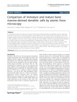
•
Photomicrograph a – the machined specimen was
machined at a very low cutting speed (2.6 m min
–1
)
e chip formation was discontinuous and the sur-
face shows an alternating eect of both chip forma-
tion and fracture, with some evidence of deposited
residual BUE. Here, the surface topography is the
result of complex interactions by various eects,
such as changes in shear angle in the contact area
between the tool and chip, plus ‘straining’ causing
increases in the chip thickness. ese phenomena
produce a variety of conditions, from strain-to-
cracking and visually introduces an irregular and
an alternating surface topography,
•
Photomicrographs a to d – cutting speeds in the
range from 11 to 59 m min
–1
, generate a continuous
chip formation. It is evident from these photomi-
crographs (b, c and d), that the surface texture was
gradually improving as the cutting speed increased,
although even at 59 m min
–1
, there was some indi-
cation of debris from re-deposited BUE here (i.e. in
‘d’),
•
Photomicrograph e – once the ‘optimum’ cutting
speed had been reached (112 m min
–1
– for this ce-
Chapter
Figure 187. The tribological action of machining and its aect on induced residual stresses and the micro-
hardness ‘foot-printing’ technique
.
Machinability and Surface Integrity
mented carbide insert grade), the surface texture
appears to be in the main, ‘good’ , with only isolated
areas of the topography exhibiting marginal work-
piece side-ow eects,
•
Photomicrograph f – when the cutting speed
was increased to 212 m min
–1
, then in these trials,
greater cutting insert wear-rate occurred and was
attributed to appreciable carbide edge breakdown,
although the surface topography indicated that an
excellent surface texture was present.
e machined surfaces produced at the lower range of
cutting speeds indicated in Figs. 188 a to d, shows evi-
dence of some re-deposited BUE material to greater-
or-lesser extent: having broken away from original
‘BUE mass’ , then being re-deposited over several
adjacent machined feed cusps (i.e. see Fig. 28a, fully-
appreciate this eect). To obtain a better and deeper
understanding of these machined surface and sub-
surface eects at the extreme conditions of either very
low, or high cutting speeds: Figs. 188 a and f, respec-
Figure 188. Some photomi-
crographs of component surfaces
machined at dierent cutting speeds
– otherwise with identical cutting
data – illustrating the surface, but not
sub-surface steel’s condition. [Source:
Watson & Murphy, 1979]
.
Chapter
tively, the following comments can be made. When
longitudinal taper-sections were taken through these
specimens’ cross-sections, the ground, polished and
etched surfaces reveal their true substrate damage. In
the case of Fig. 188a, BUE was presents on the sur-
face, moreover, there was a cutting/fracture sequence
indicated with conrmation of work-hardening hav-
ing ‘layered scales’ of with cracks and crevices beneath
them. Conversely, the test specimen machined at high
cutting speed (Fig. 188f), there is some verication of
a ‘white-layer’ formation – which is a complex metal-
lurgical phenomena found in certain ‘abused’ ferrous
workpiece situations – more will be said on this condi-
tion shortly. In fact, the ‘good’ machined surface to-
pography disguises the fact that an underlying ‘white-
layer’ condition was present, having a local recorded
hardness of 860 H
VPN
. By way of comparison, if this
same alloy steel composition had received a ‘conven-
tional’ hardness heat-treatment process: heated and
water-quenched from 1200°C, then the bulk hardness
would only be approximately 700 H
VPN
– see Appendix
12 for Hardness Comparison Tables.
From these examples of cutting speed investigative
results and the previously mentioned discussion, it is
evident that the ‘optimum’ machined surface texture
is obtained when the cutting speed is closely aligned
to that of the tooling manufacturer’s recommenda-
tions, so here in this case it is ≈112 m min
–1
, with a
correspondingly ‘good’ surface topography/integ-
rity. If the cutting speeds had been employed at the
‘higher’ cutting data (i.e. 212 m min
–1
), then one could
have been fooled into accepting this apparently ‘im-
proved’ surface topography. Nevertheless, underlying
this machined surface would be an unstable sub-sur-
face condition, which if used in a stressed and critical
in-service environment, it might potentially fail, by a
reduced fatigue-life – this is why the topic of surface
integrity is so important in today’s climate of potential
industrial litigation, when component failure occurs!
Surface Cracks and White-Layers
If any cracks are present at the free surface which ex-
tends into the material’s substrate, they are potential
sites for premature component failure – for highly
stressed in-service components. It has been reported
in the ndings of industrial enquiries into the UK
railway industry of late, that despite these railroad
tracks being precision machined and then occasion-
ally inspected by non-destructive (NDT)
86
techniques
– according to the maintenance schedule, instances
have occurred when these rails and particular on
high-speed banked corners – have delaminated. is
catastrophic rail delamination has caused several pas-
senger trains to lose contact with the rails and crash,
resulting in signicant loss of life. Hence, the method
of machining – ‘abusive’ – can contribute poor surface
integrity and to the susceptibility of these machined
surfaces to prematurely fail. In the case of milling op-
erations, it has been recognised for a number of years
that up-cut milling – alternatively termed ‘conventional
milling’ (Fig. 190a), can introduce a surface tensile re-
sidual stress into the surface layers of a milled work-
piece. If this machined component is then subjected
to both an arduous and potentially fatigue-inducing
environment, then the cyclical nature of continuous
stressing followed by its immediate stress release, can
initiate surface crack sites causing them to open-up,
which could result in premature part failure. Con-
versely, an identical machined component that has
been ‘down-cut’ – otherwise termed ‘climb-milling’
(Fig. 190b), will induce surface compressive residual
stresses. is surface layer with its residual stress com-
pression, has invariably been shown to remain closed
and thus, avoiding crack propagation and growth,
when machined under identical cutting data and en-
vironmental circumstances. Moreover, for many years,
it has been recommended that for CNC milling appli-
cations ‘climb-milling’ not only generates this favour-
able machined surface compressive stress eect, but is
a more ecient cutting process and as a result, draws
less spindle power. In Appendix 13a and b, two useful
‘nomographs, are given to determine either the cutting
data (Appendix 13a) this is related to the workpiece’s
diameter and, a diagram (Appendix 13b) to obtain the
spindle power from the anticipated chip area, respec-
tively.
In a machined surface, both craters and pits do
not pose too great a fatigue problem, as they cannot
achieve the ‘critical radius’ (i.e see Footnote 67) neces-
sary to instigate a site for crack initiation at a poten-
86 ‘Non-destructive testing’ (NDT), is a range of ‘non-invasive’
sub-surface inspection testing techniques, typically: Eddy-
current testing, Ultrasonics tests, X-ray investigation, etc., that
can, in many cases be automated for the detection of otherwise
hidden aws in the component(s).
Machinability and Surface Integrity