Báo cáo hóa học: " Research Article An Analog Processor Array Implementing Interconnect-Efficient Reference Data Shift and SAD/SSD Extraction for Motion Estimation" ppt
Bạn đang xem bản rút gọn của tài liệu. Xem và tải ngay bản đầy đủ của tài liệu tại đây (4.41 MB, 11 trang )
Hindawi Publishing Corporation
EURASIP Journal on Advances in Signal Processing
Volume 2009, Article ID 127630, 11 pages
doi:10.1155/2009/127630
Research Article
An Analog Processor Ar ray Implementing
Interconnect-Efficient Reference Data Shift and
SAD/SSD Extraction for Motion Estimation
Jonne Poikonen,
1
Mika Laiho,
1
Ari Paasio,
1
Lauri Koskinen,
2
and Kari Halonen
2
1
Department of Information Technology, University of Turku, 20014 Turku, Finland
2
Electronic Circuit Design Laboratory, Helsinki University of Technology, P.O. Box 300, 02015 Espoo, Finland
Correspondence should be addressed to Jonne Poikonen, jokapo@utu.fi
Received 25 September 2008; Accepted 30 January 2009
Recommended by Diego Cabello Ferrer
A cellular analog processor array for use in variable block-size motion estimation with a new simple method for shifting reference
image data is presented. The new shift method leads to a greatly reduced number of neighborhood connections for each cell of
the array, and allows for all shifts within the [8,8] search area to be performed in a single step, with simple digital controls. The
new shift circuitry, together with some other cell and system level optimizations , reduces silicon area and array layout complexity,
enabling faster and more efficient parallel full search motion estimation hardware. A 32
× 32 cell parallel analog test array for
reference-shift with a maximum block-size of 16
× 16, as well as absolute value/quadratic processing for variable block-size analog
motion estimation (AME) has been designed in a 0.13 μm CMOS technology.
Copyright © 2009 Jonne Poikonen et al. This is an open access article distributed under the Creative Commons Attribution
License, which permits unrestricted use, distribution, and reproduction in any medium, provided the original work is properly
cited.
1. Introduction
Cameras with (multi-)megapixel sensors have become ubiq-
uitous in even relatively low-end mobile phones. While
this makes good quality still imaging possible, the limited
amount of memory and processing power in such a battery-
powered mobile platform often prohibits the use of the best
available image quality for capturing video streams; typically
a considerably poorer video capture resolution is used. The
strong overall trend of memory technology scaling enables
the integration of increasing amounts of memory within
mobile phones. However, the increase of processing power
which is required for real-time processing of the video stream
is considerable.
An integral part of all video standards is motion
estimation (ME), which can take up to 80% of the power
consumption of a video encoder. For small frame sizes, the
ME power consumption can be reduced through algorithmic
methods, however, for megapixel resolutions these solutions
are not sufficient. Without new optimized circuit techniques,
the power consumption due to the motion estimation
process will grow beyond the capabilities of small battery-
powered platforms.
The currently applied video standards for mobile ter-
minals (e.g., H.264) employ Block-Based Motion Estima-
tion (BBME), and preferably variable block-size motion
estimation. The most fundamental operation required for
BBME is the shift of the reference-block data, to which
the current frame data is compared, after which the best-
matching new block position is determined with relatively
simple processing. A performance advantage has been sought
from performing the motion estimation operation in the
analog domain and by employing a CNN-type [1] parallel
processor array [2–8].
This paper describes the implementation of parallel
processing hardware for an analog motion estimation (AME)
array, with a focus on the implementation of a new
reference data shift method. The proposed shift imple-
mentation leads to a significant reduction in the required
cell interconnections, enabling a [8,8] cell search range to
be implemented with a simpler array-level wiring than in
previous implementations and with simple controllability.
2 EURASIP Journal on Advances in Signal Processing
shift
network
Ref. -pixel
Cu
rrent
pixel
ABS
+
Sum
of pixels
within
MB
(SSD)
QUAD
Other pixels within
macroblock
−
Processing in each pixel cell
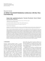
Figure 1: Cell-level functionality required for BBME.
This paper extends the original paper proposing the new
reference-shift method [9], by also describing in detail the
implementation of other circuitry for the array cell as well as
presenting the implementation of a 32
×32 cell AME test chip
that has been designed and submitted for manufacturing.
The paper is divided into seven Sections. Section 2
discusses some implementation issues relating to a motion
estimation array realization, Section 3 describes the new
reference shift method in detail, and Section 4 examines the
other circuitry in the array cell. In section 5 some important
implementation issues are discussed, Section 6 describes the
designed test array and examines the performance of other
proposed motion estimation processors, and finally some
conclusions are drawn in Section 7.
2. Analog Motion Estimation Array
Variable block-size motion estimation is based on comparing
a macroblock of pixels, typically from 4
× 4to16× 16
pixels, in the current image frame (C-frame) to blocks of
the same size within the search area of a reference frame
(R-frame). The position where the best matching of the
macroblocks in the different frames is achieved represents
the estimate for the motion in the image, that is, the
motion vector. The matching at each position is evaluated
by using a matching criterion which is typically either the
Sum of Absolute Differences (SAD) or the Sum of Squared
Differences (SSD) between the individual macroblock pixel
values in the current and reference frames. The optimal
selection of the method depends on the type of hardware
implementation, SAD is more typically used in digital
implementations because the required calculations are much
simpler. A fair approximation of SSD can be easily imple-
mented with current-mode analog circuitry, however, the
accuracy compared to an actual squaring operation is limited
by the nonideal characteristics of transistors, especially in
modern deep-submicron technologies and with low power
supply voltages. Figure 1 demonstrates the cell operations
required for an analog motion estimation array. The different
circuit blocks will be discussed in detail in the following
chapters.
In principle, the optimal implementation of analog
motion estimation would be to integrate the motion esti-
mation circuitry together with each pixel in the photosensor
array. By not having to convert the analog pixel values
into digital form before motion estimation, considerable
power savings could be achieved and the processing could be
performed for the whole frame in a fully parallel manner. In
reality this is not feasible for a megapixel sensor array, due to
the resulting excessive silicon area required by the processing
circuitry per pixel. Also, without A/D conversion, the input
frames would have to be stored in analog memories, which
creates many implementation and performance difficulties,
especially with advanced CMOS technology.
Because of these reasons, a more realistic alternative is to
separate the imager array and the analog motion estimation
processor. Even in this case the processor array cannot be
practically designed with the same spatial resolution as a
very large sensor. There are different ways to overcome this
problem. The processor array can, that is, be implemented
with the same number of columns than the image sensor,
however, with only a limited number of rows. Another
possibility is to implement the processor as a significantly
smaller but symmetrical array, which is applied to the
larger image frame in a windowed manner. Making a single
processing cell as simple and small as possible is still crucial,
since it enables the implementation of a larger processing
window, reducing the number of required iterations for a
large image size, and thus increasing the possible processing
speed.
The actual motion estimation process performed by the
array processor should be fast enough not to limit the
achievable frame rate or frame size. The efficiency of the
implementation is also heavily dependent on the speed of
data transfer between the imager and the motion estimation
processor, which means that the communication scheme
should be carefully designed. The first requirement can be
fairly easily achieved by using efficient analog current-mode
signal processing. Because the analog image data from a
sensor is always converted into digital form for further
handling and storage, also the data communication with
an external motion estimation core should be digital. This
enables high-speed I/O operations and makes a separate
analog motion estimation processor compatible with a
system environment which is otherwise fully digital.
In a motion estimation processor with digital input,
each cell of the AME array has to include two (typically
8-bit) digital to analog converters for providing data for
the two frames to be compared, and the corresponding
in-cell digital memory elements. The digital I/O for the
processor is heavily asymmetrical; the only output required
from the AME processor is digital motion vector data, that
is, the identification of the shift location which results in
the smallest block difference. The actual image data does
not have to be read out of the processor array. The motion
estimation circuitry does not have to have, nor should have,
any direct effect on the image data itself. This will prevent
additional image errors due to inevitable inaccuracies in
analog operation.
3. Shifting of Reference Data
In principle, the switching operation could be performed
by moving the pixel values step-by-step through only first
neighborhoods connections. However, this would require
current memories for intermediate storage, if implemented
EURASIP Journal on Advances in Signal Processing 3
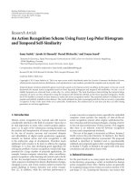
Figure 2: Cell neighborhood connections. Because the connections
are bidirectional, the number of actual wires per cell is only 8.
in an analog fashion. The large number of sequential
current memory read/write operations may slow down the
shift operation and cause additional inaccuracy, and can
potentially lead to higher power consumption from increased
control signal activity. The proposed shift method also allows
the efficient use of possible optimized search patterns, in
addition to an exhaustive full search. Shifting the values cell-
by-cell would make this much more inefficient.
The shift operation in a massively parallel array could
also be performed in a fully digital manner, solving the prob-
lems of interconnect complexity and analog inaccuracies. On
the other hand, this may lead to many new design challenges,
that is, in terms of circuit complexity, power consumption
and the implementation of the actual in-cell processing.
However, the prospect is a very interesting direction for
future research.
Figure 2 shows the neighborhood connections available
in the network. Each connection between cells operates
bidirectionally and is shared between two cells; the actual
number of physical wires per cell is only half of the number of
direct neighborhood connections. The choice between input
and output operations for each direction is implemented
with switches and logic inside the cell.
Because neighborhood connections to the 2nd and 5th
neighbors are only available in the cardinal directions (N,
E, S, and W), the shifts to the diagonal directions are
implemented by using the same neighborhood twice in the
same shift operation. The principle of the double shift is that
first a connection to either N or S is used, after which the
input to the cell is fed directly to the E or W connection of the
same neighborhood. After this, the signal can either be taken
into the target cell or to a lower neighborhood, from 5th
to 2nd or from 2nd to the 1st neighborhood. By combining
effectively 8-connected 5th and 2nd neighborhoods with an
actually 8-connected local neighborhood, all cells within an
8-cell search area can be accessed (from 1 to 5 + 2 + 1).
Because the output directions in the different neighborhoods
can be controlled individually, that is, a shift with a length of
4 can be implemented simply by moving into the opposite
direction in the lower neighborhood: East(4)
= East(5) −
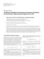
West(1). Figure 3 shows two examples of shift operations
with the proposed connectivity.
5.
4.
3.
2.
1.
(a)
3.
2.
1.
(b)
Figure 3: (a) Cell neighborhood connections. Example of (b) [8,8]
shift, (c) [4,
−2] shift.
The approach proposed here significantly simplifies
the connectivity in the array, compared to the previously
proposed methods [5, 6]. The number of neighborhood
connections per cell is now only 16, as opposed to 30 [5].
Although the number of separate cell connections required
for some shifts is now 5 compared to a previous maximum
of 3, all shifts are still implemented directly in one step,
without having to store any pixel values in intermediate
cells. The hierarchically implemented shift procedure is very
straightforward and simple to control, requiring roughly 20
global control signals, which could be reduced by including
in-cell control signal decoding. All controls could also be
generated in-cell with a dedicated state-machine, however,
in that case the cell complexity and area would be greatly
increased. The metal pitch in current CMOS technologies
is very small, which means that the number of global wires
required for the proposed circuitry can be easily routed even
over a fairly small cell size.
The layout design complexity is also greatly reduced with
the proposed shift network, because of the fewer intercell
connections and a fully symmetrical wiring arrangement;
in [5] the connections were asymmetrical, which makes
the layout design very complicated. In this case, since all
connections are bidirectional, the number of individual
neighborhood wires that have to be implemented for each
cell is only 8 and the rest of the connections are realized
automatically through symmetry.
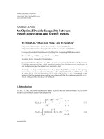
3.1. Shift Configuration. The switch configuration for a single
cell, used for the shift operation, is shown in Figure 4.The
local input to the cell is provided by a current-mode Current-
frame DAC (C-DAC) whereas the Reference-frame DAC (R-
DAC) provides the output value of the cell which is shifted
through the network. The local C-DAC current value is
subtracted from the shifted R-DAC output, propagated from
the source cell of the shift, and the current difference is
applied to the ABS + QUAD block, which is implemented
with very simple analog current-mode circuitry.
During the shift operation, the output current of the
R-DAC is lead directly through a series of simple NMOS-
transistor switches to the target cell. The simplified control
signal configuration for the shift is as follows.
4 EURASIP Journal on Advances in Signal Processing
fw2_2
out2
out5
N2
E2
W2
S2
in5
fw2_1
fw5_5
N5
E5
W5
S5
fw5_1
fw5_2
fw2_2
fw2_2
N1
NW1
N1
NE1
NW1
NE1
fw2W
fw2E
fw5W
fw5E
fw2W
fw2E
fw5W
fw5E
N2
E2
W2
S2
E5
W5
S5
R-frame
DAC
C-frame
DAC
in2
N5
fw2_2
fw5_5
fw5_5
fw5_5
Output switches
Input switches
out1
5th neighborhood bypass
5th to 2nd
5th to 1st
2nd neighborhood bypass
2nd to 1st
shift_out
no_shift
shift_in
O_N1
O_NE1
O_NW1
I_S1
I_SW1
O_N2
O_E2
O_W2
O_S2
I_S2
I_W2
I_E2
I_N2
ABS + QUAD
Current difference
Functional circuitry + input DACs & memories
O_N5
O_E5
O_W5
O_S5
I_S5
I_W5
I_E5
I_N5
I_SE1
Figure 4: Cell switch configuration for the reference shift. All switches are implemented with NMOS transistors.
3.1.1. Selection of the Correct Out put Neighborhood and
Direction. Global control signals out1, out2, and out5are
used to select the neighborhood to which the R-DAC
output current is propagated. The direction controls are
implemented with 3 bits for the first neighborhood and with
2 bits each for the 2nd and 5th neighborhoods; a single
output/input switch in the simplified schematic of Figure 4
is actually implemented either as 3 or 2 NMOS transistor
switches in series. The control signal noshift is used to
implement a [0,0] shift.
3.1.2. Selection of Propagation to a Lower Neighborhood.
Global signals fw5
1, fw5 2, and fw2 1areusedfor
moving hierarchically to a lower (closer) cell neighborhood,
in order to implement all necessary propagation paths. From
the 5th neighborhood the signal can be propagated either
to the 2nd or 1st neighborhoods and the 8-connected 1st
neighborhood can be reached from the 2nd neighborhood.
3.1.3. Selection of the Direction of Secondary Propagation.
In the 2nd or 5th neighborhoods, two propagation direc-
tions can be used at the same time. When the signal is
propagated either to North or South, another wire in the
same neighborhood can be used, either to East or West.
The local control signals fw2
2and fw5 5 in the cell are
implemented as OR( fwx
E, fwx W). This means that if
neither secondary direction (E/W) is globally enabled, the
secondary connection will not be used (e.g., fw2
2 =
LOW), and the first 2nd or 5th neighborhood connection
(N/S) has to be directed either to the input of the target cell
or to a lower neighborhood.
3.1.4. Selection of the Input Neighborhood. The neighbor-
hood which provides the input to the target cell is selected
with the global signals in2andin5. Input switches are not
required for the 1st neighborhood, because if a signal is
applied to any 1st neighborhood output wire, it is always
taken directly to the input of the neighboring target cell;
propagation to an upper hierarchy level is not possible. Sep-
arate input and output direction switches are still required
because the cell interconnect wires are used bidirectionally.
The controls for the input direction switches are hardwired
opposite to the output switches, so that each neighborhood
wire can only be accessed by a cell in one direction at a time.
3.2. Shift Network Complexity. The cell circuitry required
for the shifting consists of approximately 130 transistors,
of which roughly 100 are NMOS-type switches, while the
others account for additional inverters and logic within
the cell. The complexity of the cell circuitry is reduced,
for example, by implementing the shift-direction decoding
directly with the switches used for the shift operation itself,
EURASIP Journal on Advances in Signal Processing 5
instead of using separate decoder circuitry. The realized shift
circuitry is rather compact, however in future research and
implementations some additional optimization may still be
possible.
The complexity of the cell circuitry could be further
reduced by separating the output and input wires used for
the shift. If each neighborhood connection wire was made
one-directional (input/output), input direction selection
would not be required and a part of the switches could be
omitted. This would reduce circuit area and the resistive
effects discussed later, however, the neighborhood wiring
complexity would be greatly increased because the number
of physical wires would be doubled. In this case, simple
interconnect wiring was targeted. Also, the area requirements
of additional wiring may counteract some of the area savings
from a reduced number of transistors.
A compromise between the number of switches and
interconnect layout complexity could be reached by imple-
menting only the first neighborhood connections with
separate input/output wiring. This would reduce the number
of transistors but would not require doubling the number of
long interconnects, which have to pass over other cells, thus
limiting the additional layout design more complexity.
4. Other Cell Circuitry
In addition to the shift network, each cell of the array
includes the C-frame and R-frame DACs, which are NMOS-
type 8-bit current mode binary-weighted converters, 16
static digital memory elements for storing the DAC input
codes and the actual analog processing circuitry. The pro-
cessing circuitry consists of a current-mode absolute value
circuit followed by a current squarer circuit. This processing
circuitry is effectively the same as in an earlier proposed
AME designs [7, 8], however, the cell circuitry has been
optimized for the new array design, which does not include
current memories and in-cell current averaging. After the
fairly simple in-cell analog processing, the summing of the
cell outputs, within variable-sized macroblocks, has to be
performed, and the sums for different macroblock locations
have to be compared to find the best matching shift vector.
In the current test chip design this is done with separate
processing outside the chip.
4.1. Reference Source DAC Swapping. During the motion
estimation procedure for a continuous stream of frames,
after the motion vector for a frame has been determined, the
reference frame will typically become the current frame for
the next motion estimation step. In the AME array, where the
input images are provided by in-cell DACs, the input data for
the next C-frame is already stored in the cell as the R-frame
for the previous operation. It is therefore desirable to use that
frame data instead of writing both C-frame and R-frame data
into each cell of the array for every frame of the image stream.
Because both the C-frame and the R-frame are stored in
static digital memory registers inside the cell, the R-frame
register could be simply written into the C-frame register.
However, it is easier and more power-efficient to simply
VDD
Shifted input
from NMOS
DAC in source
cell
ABS/QUAD
Shift output
to target cell
DAC1 DAC2
Figure 5: Input configuration for current shift with DAC swapping.
swap the outputs of the two in-cell DACs in every successive
motion estimation step. Because current-output DACs and
current-mode processing are used, the output current of a
DAC can be simply redirected through a switch either to
the local difference block (used as C-DAC) or to the shift
network (used as R-DAC). This way only the reference frame
data has to be written into the cells in each motion estimation
step, and power and time is saved during the read-in phase of
the processor array.
The benefit of the DAC swapping is only truly realized
if a full image-sized processor array is implemented, that is,
the whole image is processed at the same time. However, it
maybe also be somewhat useful for I/O optimization in a
windowed operation with a relatively large window (array)
size, compared to the complete image, so that the swapping
can be used for the last processed window of the image, to
begin a new sweep with the existing DAC data. The swapping
of the DACs and the cell input configuration are illustrated in
Figure 5.
4.2. Absolute Value and Quadrature Operation. Figure 6
shows the actual processing circuitry in each cell of the array,
along with the transistor sizes. The circuitry consists of a
current-mode absolute value circuit and a current squarer.
Some additional switches have been added to make the cell
operation more flexible, so that either absolute value or
quadrature output can be used for the cells.
The difference between the shifted reference frame pixel
value and the local current-frame pixel value is realized at the
input of the absolute value (ABS) block as a simple current
subtraction. The absolute value circuit is implemented as
proposed in [10]. Depending on whether the input current
to the circuit is positive or negative (towards or away from
the input node), the input voltage will be driven either higher
or lower. The input voltage swing is amplified by the inverter,
which is connected between the input node and the gates of
the NMOS and PMOS transistors at the input of the ABS-
clock. The inverter helps to efficiently close the unwanted
and open the correct current path (direction) through the
rectifier. This results in reduced voltage variation at the
input node of the rectifier and thus improved performance,
6 EURASIP Journal on Advances in Signal Processing
VDD
5/4
5/4
VDD
1/1
0.15/1
I
diff
1/10.15/1
Sel ABS
I
out
SQ
Sel
I
SQ
8/5
M
SQ
V
abs
0.95/7
I
abs
V
cont
M
R
V
bias
Figure 6: Absolute value and quadrature circuitry. The applied
transistor dimensions (W/L)areinmicrometers.
012345
(μA)
0
10
20
30
(μA)
QUAD ABS
Figure 7: Simulated absolute value and quadratic responses of the
cell.
compared to simpler rectifier circuits [11]. The addition
of the inverter adds some extra complexity and power
consumption, however, in this case the overall circuitry is so
simple that the performance advantage is more significant.
When the current to the absolute value circuit is zero,
the input voltage is somewhere in the middle of the power
rails and a race situation is created in the inverter, leading to
static current consumption. The magnitude of this current is
limited in the cell to <1 μA by making the inverter transistors
long and very narrow as can be seen from Figure 6.
The output of the absolute value circuit is taken to an
NMOS transistor M
R
which is effectively operating as a
resistor. In normal operation, the gate voltage of transistor
M
R
is set to VDD and the voltage over M
R
is relatively small.
Therefore, the transistor is operating in the triode region as
an approximately linear resistor. The source bias voltage of
M
R
can be adjusted in order to set the correct input range for
the subsequent squaring transistor M
SQ
.
The squaring transistor M
SQ
takes as its input the
approximately linear output voltage V
abs
. The transistor is
biased so that it is operating in saturation and thus provides
an output current which is approximately quadratic with
respect to the input voltage:
I
SQ
≈
β
2
V
abs
− V
TN
2
. (1)
It has to be noted that the squaring is only approximate
and the accuracy is also affected by the inevitable nonlinear-
ity of the ABS output. Also, the transistor M
SQ
is, for layout
reasons, actually implemented as two W/L
= 8/2.5 μmNMOS
devices in series. This has only a very small effect on the
quadratic output response of the cell, as opposed to using a
single transistor. It has been shown that an exact quadrature
operation is not really necessary, nor even the most optimal
solution [12]. Figure 7 shows the simulated responses of the
absolute value circuit and the quadrature transistor when
the input current was swept from 0 to 5 μA, which can be
considered to be a suitable signal range for the circuitry.
4.3. SAD/SSD Operation. The cell circuitry shown in
Figure 6 can provide two different output values. When
V
cont
= VDD, switch ABS is turned off and SQ is conducting,
the output of the cell will be the squared response to the
input difference. If V
cont
= 0 and ABS is conducting with SQ
turned off, the output current of the absolute value circuit
will be directed to the cell output. This means that either
the absolute value or quadratic output current can be read
out from the same cell output node and either SAD or SSD
operation can be selected and tested. The motion estimation
process can be described as the minimization of the equation
D
N
(dx, dy) =
x+N
v
, y+N
h
i=x, j=y
|ref (i + dx, j + dy) − cur (i, j)|
p
,
(2)
where N
v
xN
h
is the macroblock size, (dx, dy) the applied
shift vector for the reference frame, (x, y) the top-left pixel
of the macroblock and p depends on whether SAD (p
= 1)
or SSD (p
= 2) is applied.
The summing of the cell currents within the macroblock
required for SAD/SSD is simply realized by connecting all of
the output nodes of selected cells to a global output wire.
Each cell receives a row and a column signal which are used
to create the cell select (Sel) signal. The cells to be summed
together, that is, ones belonging to the same macroblock,
are selected with peripheral row/column decoder circuitry,
which is capable of addressing several rows/columns at a
time in a programmable fashion. The sum currents from
different macroblocks can then be evaluated, for example,
with an ADC, and compared, either one block at a time
in a sequential manner or with fully parallel comparison
circuitry.
EURASIP Journal on Advances in Signal Processing 7
The implementation of the comparison circuitry has to
be carefully optimized in order to reach the best possible
performance. The integration of the evaluation circuitry on
the same chip as the array is a subject of further research;
in the designed 32
× 32 test chip, the sum current is routed
off-chip for measurement. However, because the SAD/SSD
comparison, which is not a pixel-parallel operation, is not
performed within the array itself, the cell circuitry can be
kept very simple, allowing for a larger array size. Also, the
measurement and evaluation circuitry can be optimized
independently of the cell array, making the design more
flexible and efficient.
Because the two outputs (ABS/SQ) result from different
types of sources (PMOS/NMOS, resp.) also the cell selection
switches (Sel) were implemented separately for both current
paths. This allowed the use of the correct type of devices, in
order to minimize the effect of the switches on the output
current value. The different current polarities naturally also
have to be accounted for in the measurement circuitry.
In the implemented chip the SAD/SSD evaluations will be
performed off-chip, however, the circuitry could also be
integrated in the periphery of the AME array.
5. Implementation Issues
The circuit operation was simulated at the transistor level
with a 9
× 9 cell array. A 0.13 μm standard CMOS technology
was used with VDD
= 1.2 V. A potentially difficult design
issue in the proposed method is that the shifting of the
reference value as a current signal makes the implementation
vulnerable to resistive drops in the large number of series-
connected switches used for the [8,8] neighborhood con-
nectivity. The resistive effects can lead to deterministic shift-
dependent offsets, which may cause errors in the motion
estimation process.
5.1. Resistive Effects. The analog ABS/QUAD circuitry
receives as input the difference between two current-mode
DAC outputs. The applied current-mode signaling may
lead to resistive distance-dependent offset in the difference
extraction. A large current value causes a significant resistive
voltage drop over the shift switches, which are in series
between the R-DAC in the source cell and the diode-
connected input transistor of the PMOS current mirror in
the target cell. This lowers the output voltage of the R-
DAC, which leads to current variations due to channel length
modulation in the DAC transistors, in the worst case the
DAC transistors may even start to come out of saturation.
The channel length modulation can be mitigated to some
extent by using long-channel transistors in the DAC, in this
case L
= 4.88 μm was used for the unit current source in the
DACs.
In order to simplify the design, the two DACs should
be of the same type (NMOS/PMOS), which means that one
of the inputs has to be mirrored in order to perform the
subtraction. The type of the switches used (NMOS/PMOS) is
dependent on the DAC-type and on the current mirror con-
figuration. Simulations showed that PMOS switch transistors
0 100 200 300 400
Time (ns)
−1
0
1
2
3
4
5
6
(μA)
[8, 8]
no
shift
[1, 1]
Figure 8: Transient simulations of [0,0], [1,1], and [8,8] shifts, with
high-speed transistor switches.
of a reasonable size exhibited considerable resistive voltage
drops due to their low conductance. Because this would lead
to large offset errors which depend on the shift distance,
NMOS transistor switches were selected. This leads to a
cell configuration where the output current of an NMOS-
type R-DAC is propagated through (NMOS) switches and
mirrored with a PMOS current mirror in the target cell as
shown in Figure 5. The larger conductance of the NMOS
switch transistors resulted in a much reduced distance effect,
compared to PMOS switches.
The selection of the correct transistor type within the
applied CMOS process can lead to considerable benefits
in terms of both performance and cell area. Using lower-
threshold and higher conductivity high-speed (HS) tran-
sistors available in the CMOS technology, enables the use
of smaller switches, leading to more compact cell circuitry.
The larger leakage current in HS transistors is not a serious
problem in this case because of the many switches in
series in the shift network. Also, the voltage differences
over nonconducting switches between cells in the array are
relatively small, because the output current of each DAC in
the array is always taken into the same resistive load (i.e.,
diode-connected transistor).
Figure 8 shows a transient simulation comparing three
different shift operations: [dx,dy]
= [8,8], [1,1], and [0,0]
(no shift), the applied current magnitude was 5 μAwhich
is specified to be the maximum input current for the cell
circuitry. The output of the R-DAC in the source cell was
constant and the switch to the output neighborhood was
turned on at 100 nanoseconds. These cases correspond to
different numbers of switches present in the current path,
that is, different resistive voltage drops. The shift network
was implemented with high-speed (HS) NMOS transistors,
with W
= 0.5 μmandL = 0.13 μm. The two extrema are
[0,0] with only 2 switches and [8,8] with more than 20
switches in the current propagation path. The simulated
difference in the DAC output current between theses cases
8 EURASIP Journal on Advances in Signal Processing
0 100 200 300 400
Time (ns)
0
5
10
15
20
25
30
(μA)
ABS/QUAD transient output response
ABS
QUAD
Figure 9: Transient settling of the cell output for ABS and QUAD
operations.
is approximately 40 nA, with low-leakage transistors of the
same size the output difference would be more than doubled.
The resistive loss in the switches should not be a limiting
design issue for the proposed circuitry, since even with the
maximum input value, the difference in the shifted currents
is small. However, extensive simulations and testing with
natural image streams on the manufactured array is neces-
sary to verify if further optimization of the shift operation
is necessary. The distance effects could be mitigated, for
example, by applying cascode techniques to the DACs, to
increase output resistance, or by taking the shift distance into
account in the SAD/SSD evaluation phase. Other common-
mode nonlinearity effects caused by the analog processing
circuitry, which are not dependent on shift distance, should
not be critical to the AME operation if they do not affect the
ordering in the following macroblock comparison.
5.2. Mismatch Effects. Mismatch between the analog transis-
tors in the processor cell is the most significant source of
errors in the proposed motion estimation architecture. The
achieved accuracy is proportional to the area of a device
[13], therefore the circuitry should be made as simple as
possible and, for example, unnecessary current mirroring
operations should be avoided. In the shift operation, the
current is only mirrored once through the local PMOS
mirror. Another current mirror is required for the absolute
value circuit. Because of the small number of devices, the
mirror transistors can be relatively large, in the realized test
chip devices with W/L
= 5/4 μmwereused.
The mismatch variation in the different parts of the
cell circuitry was simulated with a Monte Carlo simulator,
with mismatch models provided by the manufacturer. The
simulated output standard deviation of the input DAC at
the full signal output of 5 μA was approximately 0.5%. The
simulated relative output standard deviation of the absolute
value current, without input mismatch, with the maximum
input was approximately 0.6%. The squaring operation
introduces additional mismatch variation. The simulated
standard deviation in the quadrature output, which also
includes the absolute value variation, but not input signal
mismatch, was approximately 2.3%.
Fixed-pattern noise in the input image, due to the input
DACs could, at least to some extent, be corrected by adjusting
(predistorting) the digital input codes for different cells. The
subsequent current summing operation within the whole
macroblock, which results in the actual evaluated signal from
the array for a given shift operation, leads to averaging of
the individual cell output errors. The averaging is naturally
more prominent for a larger block size. The total effect of
the mismatch variation on the complete motion estimation
operation is a very complex issue, since the actual realized
inaccuracy is totally signal- and image-dependent. System
level simulations and measurements with realistic image sizes
and a real-world video streams are required to accurately
characterize the performance of the AME array. This is not
within the scope of this paper, but will be addressed in
further research, with the help of the designed test array.
Because the analog circuitry inside each cell is very
simple, the transistors can be made fairly large. However,
minimal transistor area should still be targeted in order to
maximize the spatial resolution or to minimize the area of
the processor array. Also, because the whole image cannot
be practically processed with the array at the same time, also
the speed of operation should be maximized by targeting the
smallest possible capacitive loads, that is, smallest possible
transistors. In this respect the application of area-efficient
mismatch compensation techniques in the AME cell, such as
the one discussed in [14], should be considered.
5.3. Speed and Other Performance Issues. The delay in the
shift operation can be observed from Figure 8.Itcanbe
noticed that the maximum delay, in the [8,8] shift, is
approximately 80 nanoseconds. This delay is defined by the
resistance of the shift switches and the capacitance from
the current mirror in the target cell, which had a transistor
size of 5/4 μm in the final design. The settling time of the
analog absolute value and squaring circuitry is shown in
Figure 9, where the input difference was changed from 5 μA
to 2 μA at time zero. It can be noticed that the outputs
settle to their new values in less than 200 nanoseconds. In
practical operation also the delay of the evaluation circuitry
and I/O has to be considered, however, it can be seen that the
switched-current cell operation is relatively fast. The effects
of device mismatch on the delay are negligible.
The inclusion of in-cell DACs for providing the input
frames also leads to additional benefits related to the analog
circuit implementation. Because the input currents are
always provided by active DACs and no dynamic current
memories are used, effects such as charge injection and
memory retention problems due to leakage are not an issue,
since the input values are static and robust. An important
issue to be considered in further research, in terms of
performance, is the optimal implementation of the array
I/O and especially the writing of the in-cell DACs, so that
a large image frame can be processed fast enough and with
sufficiently low power consumption.
EURASIP Journal on Advances in Signal Processing 9
6. AME Test Array
A32× 32 cell test array was designed in the 0.13 μm6M
digital CMOS technology with the high-speed transistor
option, for evaluating the performance of the proposed
motion estimation approach in practice. The chip enables
the evaluation of the motion estimation operations within
a [8,8] search range and a 16
× 16 maximum block size. The
size of the actual active array is 16
× 16 cells, an 8-cell wide
boundary is required for providing input values to the 16
×16
cell active area, with a maximum shift distance of 8 cells. In
practice the analog processing circuitry in the boundary cells
is unnecessary, however, in the test chip layout design it was
simpler to just use basically the same cell for the boundary,
although with some wires and controls disconnected. Also,
because the DACs (+memories) and the shift network take
up most of the cell area, as can be seen from Figure 11,
leaving out the processing circuitry would not have lead to
significant area savings.
The layout of the array is shown in Figure 10. The layout
of a single array cell is shown in Figure 11, with the different
functional sections of the cell highlighted. The size of the
chip is approximately 1.5
× 1.7mm
2
and the size of a single
cell is approximately 30
× 35 μm
2
. The periphery of the array
includes row-wise buffers for the global control signals and
address decoders which enable the simultaneous selection of
multiple rows/columns for different block-size summation
operations. The sum current to be evaluated is available from
a global wire, which is only connected to the outputs of the
active 16
× 16 cell array and taken to a chip output pad for
external evaluation.
Thedigitalcontrolforthearrayaswellastheevaluation
and comparison of the SAD/SSD results will be initially
realized with an additional FPGA chip and an off-chip ADC.
For a complete motion estimation processor realization also
these operations have to be optimized and implemented
with dedicated on-chip circuitry for optimal performance.
However, at this stage a more thorough examination of the
analog cell array through chip measurements is required
to validate the feasibility of the approach, for example, in
terms of speed and accuracy, and to derive more exact
specifications for the remaining hardware and the whole
system. Many design choices, such as the practical array size
are still open to optimization.
6.1. Related Work. Since the complete motion estimation
system has not been realized at this time, it is difficult to
directly compare the performance of the proposed circuitry
to other implementations. Also, the total system perfor-
mance is a compromise between multiple factors, such as
picture quality, bitrate, power consumption, and cost (i.e.,
silicon area). The performance of the underlying analog
processing hardware has to be first evaluated in detail with
measurements before making quantitative comparisons to
other implementations. For example, the practical accuracy
and robustness of the proposed analog processing, which is
difficult to examine comprehensively with simulations, also
affects the choice of the ME algorithm. The choice between
implementing a full search operation and for example, a
Figure 10: Layout of the 32 × 32 AME processor array. The active
processing area of 16
× 16 cells is highlighted in the middle or the
array.
ABS + QUAD
Shift network
MEM
2
×
DAC
Figure 11: Layout of a single array cell with different functional
sections highlighted.
gradient descent search (GDS) algorithm, has a very large
effect on the number of required pixel operations, that is,
also on the power consumption. However, the parameters
reported from ME implementations in the field are briefly
reviewed to estimate the performance that should be targeted
and improved upon.
Few separate ME realizations have been presented.
Current ME realizations are typically embedded within
full audio-video codecs. Comparing the presented work to
such implementations is difficult due to the fact that little
specific information (such as power consumption) on the
ME part is available. The most comprehensively reported
motion estimation implementations have been digital
chips. In [15], a 0.4 mW (QCIF@15 fps, 0.85 MHz)/2.5 mW
10 EURASIP Journal on Advances in Signal Processing
(CIF@30 fps, 6.75 MHz) motion estimation IC, in 0.18 μm
technology with a 1.0 V power supply, using a gradient
descent search algorithm was presented. As the design does
not incorporate frame memory the stated power consump-
tion figures do not include the data transfer between the
frame memory and local search area memories. In [15], it is
also estimated that the power consumption of a Full Search
QCIF@15 fps ME IC would be in the range of 20 mW. In
[16], a 16.2 mW QCIF@15 fps motion estimation IC using
pixel wordlength truncation was presented. The chip has
a 20 MHz clock frequency (the operating voltage was not
stated) and is implemented with 0.18 μm technology. The
design incorporates frame memories whose portion of the
power consumption is 11.7 mW. In [17], a 1920
× 1080
designed for a power supply of 1.0 V and a clock frequency
of 81 MHz and is implemented with 0.13 μmtechnology.
The estimated power consumption is 65 mW without frame
memories.
For H.264 [18] presents a 720
×480 SVGA@30 fps systolic
array design that incorporates Full Search for the seven
different block sizes of H.264. With 0.35 μmtechnologyand
a clock frequency of 67 MHz (the operating voltage is not
stated) the design has a simulated power consumption of
737 mW without frame memories. In [19], a QCIF@15 fps
implementation using variable block-size Full Search is
presented. With 0.13 μm technology, a clock frequency of
6.7 MHz, and an operating voltage of 1.2 V the design has
a simulated power consumption of 9.1 mW without frame
memories. Both of these variable block-size ME implemen-
tations operate by computing the distortion measure values
for the smallest block size and then combining these values
to form the distortion measures for the larger block sizes.
Also, neither of these designs comments on the choice of the
optimal block size.
In other proposed block-based analog motion estimation
approaches [2, 3], although the computation, memory,
and data transfer are analog, the architectures resemble
conventional digital ME processors. This is in contrast
to the proposed work which proposes an interconnected
analog parallel processor architecture. In both [2, 3], only
the picture quality results are presented which, without
presenting the effect on bit-rate, is not fully meaningful and
makes comparison to other implementations difficult. For
the CNN-based image stabilization architecture presented in
[4] no power consumption or processing figures were given.
Additionally, the effect of error in the ME distortion measure
hasbeenstudiedin[20, 21].
At the time of writing the designed 32
× 32 cell chip
is being manufactured and measurement results, further
analysis and comparison to the other implementations,
based on experimental results, will be presented in future
publications.
7. Conclusion
This paper presented an analog motion estimation array
with a new cell neighborhood configuration and the required
circuitry for reference image shifting. In the otherwise very
simple AME cell architecture, the shift network is clearly the
most complex aspect of the implementation. Compared to a
previously proposed method, considerable savings in array
level interconnect complexity are achieved. The new shift
method thus allows for a more efficient implementation of
the analog motion estimation array. Transistor level simula-
tions show that the method and the related analog processing
circuitry can be applied for high-speed operation and with
sufficient accuracy. A realistic performance comparison with
other proposed motion estimation circuit architectures can
be achieved in future work, based on measurements of the
implemented 32
× 32 test array.
Acknowledgment
This work has been supported by the Academy of Finland
projects 107645 and 123354.
References
[1] L. O. Chua and L. Yang, “Cellular neural networks: theory,”
IEEE transactions on Circuits and Systems, vol. 35, no. 10, pp.
1257–1272, 1988.
[2] A. Tomasini, M. Brattoli, E. Chioffi,G.Colli,D.Gerna,and
M. Pasotti, “B/W adaptive image grabber with analog motion
vector estimator at 0.3 GOPS,” in Proceedings of the 42nd IEEE
International Solid-State Circuits Conference (ISSCC ’96),pp.
94–95, San Francisco, Calif, USA, February 1996.
[3] M. Panovic and A. Demosthenous, “A low-power analog
motion estimation processor for digital video coding,” IEEE
Journal of Solid-State Circuits, vol. 41, no. 3, pp. 673–683, 2006.
[4] Y C. Cheng, J F. Chung, C T. Lin, and S C. Hsu, “Local
motion estimation based on cellular neural network technol-
ogy for image stabilization processing,” in Proceedings of the
9th IEEE International Workshop on Cellular Neural Networks
and Their Applications (CNNA ’05), pp. 286–289, Hsinchu,
Tawian, May 2005.
[5] L. Koskinen, J. Marku, A. Paasio, and K. Halonen, “Archi-
tecture for analog variable block-size motion estimation,” in
Proceedings of the 14th IEEE International Conference on Image
Processing (ICIP ’07), vol. 2, pp. 493–496, San Antonio, Tex,
USA, September 2007.
[6] L. Koskinen, K. Halonen, and A. Paasio, “Efficient shift of
reference data in analog motion estimation,” in Proceedings
of the 9th IEEE International Workshop on Cellular Neural
Networks and Their Applications (CNNA ’05), pp. 130–133,
Hsinchu, Tawian, May 2005.
[7] L. Koskinen, A. Paasio, and K. Halonen, “3-neighborhood
motion estimation in CNN silicon architectures,” in Proceed-
ings of IEEE International Symposium on Circuits and Systems
(ISCAS ’04), vol. 5, pp. 708–711, Vancouver, Canada, May
2004.
[8] J. Marku, L. Koskinen, and A. Paasio, “A 130 nm implemen-
tation of analog variable block-size motion estimation cell,”
in Proceedings of the International Symposium on Integrated
Circuits (ISIC ’07), pp. 57–60, Singapore, September 2007.
[9] J. Poikonen, M. Laiho, A. Paasio, L. Koskinen, and K. Halonen,
“Interconnect-efficient reference data shift for optimized
analog motion estimation,” in Proceedings of the 11th IEEE
International Workshop on Cellular Neural Networks and
Their Applications (CNNA ’08), pp. 102–107, Santiago de
Compostela, Spain, July 2008.
EURASIP Journal on Advances in Signal Processing 11
[10] A. Rodr
´
ıguez-V
´
azquez, R. Dom
´
ınguez-Castro, F. Medeiro, and
M. Delgado-Restituto, “High resolution CMOS current com-
parators: design and applications to current-mode function
generation,” Analog Integ rated Circuits and Signal Processing,
vol. 7, no. 2, pp. 149–165, 1995.
[11] J. Poikonen and A. Paasio, “An area-efficient full-wave current
rectifier for analog array processing,” in Proceedings of IEEE
International Symposium on Circuits and Systems (ISCAS ’03),
vol. 5, pp. 757–760, Bangkok, Thailand, May 2003.
[12] L. Koskinen, M. Laiho, A. Paasio, and K. Halonen, “Motion
estimation matching criterion computation with analog cir-
cuits,” in Proceedings of the 8th International Workshop on
Cellular Neural Networks and Their Applications (CNNA ’04),
pp. 216–221, Budapest, Hungary, July 2004.
[13] M. J. M. Pelgrom, A. C. J. Duinmaijer, and A. P. G. Welbers,
“Matching properties of MOS transistors,” IEEE Journal of
Solid-State Circuits, vol. 24, no. 5, pp. 1433–1439, 1989.
[14] J. Marku, K. Virtanen, J. Maunu, J. Poikonen, and A. Paasio,
“Current mismatch and nonlinearity compensation in mixed-
mode array processors,” in Proceedings of the 11th IEEE
International Workshop on Cellular Neural Networks and Their
Applications (CNNA ’08), pp. 75–80, Santiago de Compostela,
Spain, July 2008.
[15]M.Miyama,J.Miyakoshi,Y.Kuroda,K.Imamura,H.
Hashimoto, and M. Yoshimoto, “A sub-mW MPEG-4 motion
estimation processor core for mobile video application,” IEEE
Journal of Solid-State Circuits, vol. 39, no. 9, pp. 1562–1570,
2004.
[16] C W. Yoon and H J. Yoo, “Low power motion estimation
and motion compensation block IPs in MPEG-4 video codec
hardware for portable applications,” IEICE Transactions on
Electronics, vol. E86-C, no. 4, pp. 553–560, 2003.
[17] M. Miyama, O. Tooyama, N. Takamatsu, et al., “An ultra
low power motion estimation processor for MEPG2 HDTV
resolution video,” IEICE Transactions on Electronics, vol. E86-
C, no. 4, pp. 561–569, 2003.
[18] Y W. Huang, T C. Wang, B Y. Hsieh, and L G. Chen,
“Hardware architecture design for variable block size motion
estimation in MPEG-4 AVC/JVT/ITU-T H.264,” in Proceed-
ings of IEEE International Symposium on Circuits and Systems
(ISCAS ’03), vol. 2, pp. 796–799, Bangkok, Thailand, May
2003.
[19] S. Y. Yap and J. V. Mccanny, “A VLSI architecture for advanced
video coding motion estimation,” in Proceedings of the 14th
IEEE International Conference on Application-Specific Systems,
Architectures, and Processors (ASAP ’03), pp. 293–301, The
Hague, The Netherlands, June 2003.
[20] M. Tartagni, A. Leone, A. Pirani, and R. Guerrieri, “A block-
matching module for video compression,” in Proceedings of
IEEE Symposium on Low Power Electronics, pp. 24–25, San
Diego, Calif, USA, October 1994.
[21] M. Panovic and A. Demosthenous, “Architectures for analog
motion estimation processors: a comparison,” in Proceedings
of IEEE International Symposium on Circuits and Systems
(ISCAS ’05), vol. 5, pp. 4566–4569, Kobe, Japan, May 2005.