Báo cáo hóa học: "Research Article An Adaptive Multipath Mitigation Filter for GNSS Applications" pptx
Bạn đang xem bản rút gọn của tài liệu. Xem và tải ngay bản đầy đủ của tài liệu tại đây (825.88 KB, 10 trang )
Hindawi Publishing Corporation
EURASIP Journal on Advances in Signal Processing
Volume 2008, Article ID 214815, 10 pages
doi:10.1155/2008/214815
Research Article
An Adaptive Multipath Mitigation Filter for GNSS Applications
Chung-Liang Chang and Jyh-Ching Juang
Department of Electrical Engineering, National Cheng Kung University, Tainan 70101, Taiwan
Correspondence should be addressed to Chung-Liang Chang,
Received 27 June 2007; Revised 15 November 2007; Accepted 5 January 2008
Recommended by Jonathon Chambers
Global navigation satellite system (GNSS) is designed to serve both civilian and military applications. However, the GNSS perfor-
mance suffers from several errors, such as ionosphere delay, troposphere delay, ephemeris error, and receiver noise and multipath.
Among these errors, the multipath is one of the most unpredictable error sources in high-accuracy navigation. This paper applies
a modified adaptive filter to reduce code and carrier multipath errors in GPS. The filter employs a tap-delay line with an Adaline
network to estimate the direction and the delayed-signal parameters. Then, the multipath effect is mitigated by subtracting the
estimated multipath effects from the processed correlation function. The hardware complexity of the method is also compared
with other existing methods. Simulation results show that the proposed method using field data has a significant reduction in
multipath error especially in short-delay multipath scenarios.
Copyright © 2008 C L. Chang and J C. Juang. This is an open access article distributed under the Creative Commons Attribution
License, which permits unrestricted use, distribution, and reproduction in any medium, provided the original work is properly
cited.
1. BACKGROUND AND MOTIVATION
In recent years, the Global navigation satellite system (GNSS)
has been extensively used in navigation services to provide
users with information of positioning accuracy and integrity.
However, the performance of GNSS in navigation and sur-
vey is subject to several errors, such as ionosphere delay, tro-
posphere delay, and receiver noise and multipath. Among
these errors, multipath is the major error source in precision-
oriented GNSS applications. The multipath effect is caused
by extraneous reflections of the satellite signal from nearby
objects, such as buildings, the ground, trees, and water sur-
faces that reach the receiver by way of multiple paths. For
GNSS, the multipath initiates tracking errors in the receiver
and may lead to ranging error of up to 100 m. The influ-
ence of multipath as an error source has resulted in the
development of different multipath mitigation techniques.
These techniques are typically categorized in terms of an-
tenna design, improved receiver internal architecture, and
postprocessing of discernible objects. The drawback of an-
tenna design lies in the extra hardware cost. The effective-
ness of postprocessing may be limited in accordance with
short-delay multipath. The paper thus focuses on the de-
sign of receiver internal architecture for multipath mitiga-
tion.
A survey of multipath mitigation techniques is presented
as follows to serve as a comparison reference of performance
and complexity. Hagerman [1] and Spilker Jr. [2]analyzed
the effect of multipath error by using a conventional receiver
tracking loop which contains phase lock loop (PLL) and de-
lay lock loop (DLL). The conventional correlation encom-
passes the 70–80 m tracking error that employs the DLL with
one chip of early-late spacing in multipath environment.
Van Dierendonck et al. [3] first proposed the narrow cor-
relation to effectively mitigate multipath effects and decrease
the tracking error to about 8–10 m. The narrow correlation
employs a DLL by narrowing the spacing between early and
late correlators. However, as described by van Nee [4, 5]and
Braasch [6], multipath can lead to an offset in the measured
time delay that cannot be erased by either smoothing or nar-
rowing correlator receivers.Townsend and Fenton [7]pro-
posed a multipath estimation technique (MET) by using the
slope of the autocorrelation function to estimate the code
phase offset delay of the direct signal.Yet, this technique has
been utilized to reduce only code-phase error in DLL and
the effect of PLL carrier-phase error is not considered. From
these reasons, van Nee et al. [8] employed a multipath esti-
mation delay lock loop (MEDLL) to estimate multipath sig-
nals and mitigate code and carrier-phase errors. To achieve
this, the incoming signal is separated into its line-of-sight
2 EURASIP Journal on Advances in Signal Processing
(LOS) and multipath components in MEDLL. The adop-
tion of the LOS component has made possible the unbiased
measurement of code and carrier phase. Performance evalua-
tion of conventional correlation, narrow correlation, and the
MEDLL, regarding multipath mitigation capability, was con-
ducted by Townsend et al. [9] for GPS C/A code. The MEDLL
presents better performance than the conventional correla-
tion and narrow correlation. Nevertheless, it does not com-
pletely cancel out all multipath errors. This is due to mul-
tipath signals with short delays being difficult to eliminate.
In addition, the MEDLL depends on a maximum likelihood
search, which is an extensive computation load.
Garin et al. [10] utilized strobe and edge correlators to
achieve discriminator function shaping through the combi-
nation of two different narrow correlation discriminators.
This method modified the DLL design by employing the nar-
row early-late spacing and expanding the correlation band-
width. However, a disadvantage is that the tracking capability
of the DLL is reduced. Afterwards, the enhanced strobe cor-
relator has been proposed and adopted to mitigate both code
and carrier-phase errors and decrease the error to 24 meters,
which is about 0.08 chip [11]. Laxton and DeVilbiss [12] also
employed a modified rake DLL (MRDLL) technique to esti-
mate the LOS signal along with those of all multipath com-
ponents. Even though the MRDLL reduces the code-phase
error in DLL and the carrier-phase error in PLL, it would take
a large number of correlators for estimation and consume a
great deal of hardware resources.
An Early1/Early2 (E1/E2) tracker has also been proposed
by van Dierendonck and Braasch [13]. In this method, two
correlators with chip spacing are located on the early slope
of the autocorrelation function. The major advantage of this
approach lies in the fact that non-pseudorange errors are
caused by multipath signals arriving after this (early) track-
ing point. Nevertheless, as the distance of the tracking point
from the correlation peak increases, the noise performance
decreases. In other words, the noise performance degrades
when the E1 and E2 are shifted to the left slope of the corre-
lation. Apparently, each method consists of not only advan-
tages but also inherent limitations as addressed by Braasch
[14] who investigated the theory behind each multipath mit-
igation technique and offered a performance comparison.
Chaggara et al. [15] proposed the multicorrelator tech-
nique for multipath parameters estimation. Though this
technique enhances the performance of multipath mitiga-
tion in DLL and PLL, it requires a great number of corre-
lators for estimation and consumes a great deal of hardware
resource. Irsigler and Eissfeller [16]providedasurveyofcur-
rent multipath mitigation techniques that are able to mini-
mize code and/or carrier multipath. The optimal code mul-
tipath mitigation is achieved by adopting a linear combina-
tion of several correlators or equivalently correlated the in-
coming signal with a code-tracking reference function [17].
This technique is utilized in BPSK(1) and BOC(1,1) signals
for infinite, 16 MHz and 8 MHz bandwidths. An analysis of
the influence of coherent and noncoherent GPS receiver code
tracking architecture on the carrier phase multipath error in-
cluding a thorough validation of carrier phase multipath the-
ory was presented [18, 19]. This research provided a theo-
retical structure which served as reference for simulation of
multipath mitigation techniques.
From a review of the above mentioned techniques, it is
implied that almost all of the techniques are based on two
key concepts. The first is discriminator function shaping and
the second is correlation function shaping. The advantage of
the discriminator function shaping technique is the reduced
complexity of hardware and software. One of the benefits
of correlation function shaping, both the MEDLL and the
MRDLL, is the decrease of carrier phase multipath. The lack
of performance improvement for short-delay multipath sig-
nals is by far the most prominent feature of every receiver.
This matters a great deal in the application of multipath mit-
igation. If a technique involves only short-delay multipath,
then the best correlation function shaping receiver will not
outperform a traditional one.
In this paper, an adaptive filtering approach application is
proposed in the GPS multipath mitigation. The approach is
based on the correlation function shaping technique which
estimates the direct plus multipath signal parameters, then
separates the delayed signal from the received signal simul-
taneously. The processed output signal is then subtracted
from the measured autocorrelation value of received signal.
Simulation results in multipath environments are presented
to compare the performance of the proposed method with
some of the recently developed high-performance multipath
mitigation techniques. It is confirmed that the method is well
suited in the multipath environment, especially in the short-
delay multipath environment where the computation load
and complexity are low with the best performance. In ad-
dition, this method is also effective in eliminating both code-
phase error and carrier-phase error. However, the latter is ne-
glected in some of the reviewed techniques detailed above.
The remainder of this paper is organized as follows.
Section 2 gives an overview of how multipath affects GPS re-
ceivers. Section 3 describes how the proposed adaptive filter-
ing method is applied in multipath mitigation. Performance
analysis and simulation results are given in Section 4. Then
conclusions are provided in Section 5.
2. MULTIPATH OVERVIEW
Most communicative systems are subject to multipath. The
multipath phenomenon can degrade the system performance
and reduce the range of measurement accuracy from cen-
timeters to several meters [20]. Multipath is caused by re-
flections of satellite signals from such objects as the ground
or nearby buildings. The reflected signal takes more time to
reach the receiver of the direct or LOS signal. In GPS, the de-
sired signal is only the direct path signal. All other signals dis-
tort the desired signal and cause errors in ranging measure-
ment. With the presence of multipath, the incoming code,
discriminator functions, and correlation function are all dis-
torted. Analytically, the direct-path and multipath compo-
nents can be managed in separate ways.
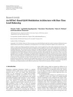
Figure 1 shows the tracking errors of the early-late dis-
criminator output caused by multipath in DLL. The track-
ing errors primarily come from distortion of the correla-
tion function with the received IF signal. In the direct-path
C L. Chang and J C. Juang 3
−1
−1.5
−0.5
0
0.5
1
1.5
Discriminator output
−1.5 −1 −0.500.511.5
Tracking error (chips)
Multipath
Direct only
Direct plus multipath
Composite distorted discriminator function
Direct plus in-phase
multipath
Figure 1: Composite distorted of early-late discriminator.
case, the ideal case is when the discriminator function passes
through zero while the code tracking error is zero. Neverthe-
less, with the presence of multipath, the distorted function
has a zero-crossing at a nonzero code tracking error. With the
direct signal, when the relative multipath phase is 0 radians,
the multipath component is in phase and with π radians, the
multipath component is out of phase. Therefore, multipath
error analysis is related to simulation of direct and indirect
path signals and is the determination of the zero crossing of
distorted discriminator function. Three multipath parame-
ters must be considered: strength, delay, and phase. The ab-
solute value of each parameter is independent.
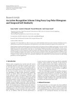
Figure 2 shows the example result for the theoretical mul-
tipath error envelope versus the multipath delay. This simu-
lation is provided in the case of infinite bandwidth receiver
filter, one-chip early-late spacing and unchanged multipath
amplitude. In addition, the code autocorrelation sidelobes
have been ignored.
The multipath error can be determined, for a given mul-
tipath to direct ratio, by fixing the upper bounds relative
multipath phase at 0 radians, the lower bounds at π radians,
and by adjusting the relative multipath delay. At each delay
point, the distorted discriminator curve is decided, while the
zero-crossing point and multipath error are calculated. The
error will fall somewhere between the bounds shown in the
error envelope, if the multipath has any phase other than 0
or π radians. Based on the influence of multipath on GPS
receiver, a solution method is proposed in the following sec-
tion.
3. MULTIPATH MITIGATION METHODOLOGY
3.1. System description
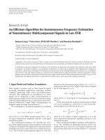
The block diagram of the multipath mitigation system is
shown in Figure 3. The received signal is processed in a RF
−0.25
−0.2
−0.15
−0.1
−0.05
0
0.05
0.1
0.15
0.2
0.25
DLL tracking error (chips)
00.511.5
Relative multipath delay (chips)
Multipath error envelope
In-phase multipath
(0 deg)
Out-of-phase multipath
(180 deg)
Figure 2: Multipath error envelope for a conventional, one-chip
early-to-late DLL receiver. Multipath component is half the strength
of the direct signal.
filter, then downconverted and sampled to a digital IF sig-
nal. The tracking module performs the correlation algorithm
in the PLL and DLL from the IF signal. The tracking mod-
ule acquires the GPS signal, the output of the code phase
and the carrier phase of the PLL and DLL is obtained. The
multipath estimator is used to estimate the correlation pa-
rameter of multipath, based on the modified adaptive fil-
ter by employing duplicated signal and digital IF signal. As
shown in Figure 3, the estimated signal parameters are then
sent to the correlation decomposer and the correlation value
of multipath signal is determined in the multipath cancel-
lation area. The estimated delayed signal is recreated at the
modified adaptive filter and is subtracted from the correla-
tion value of the received signal. The detailed process of the
multipath estimator, the correlation value decomposer, and
the multipath cancellation will be addressed in the following
subsections.
3.2. Multipath model and modified adaptive filter
In the case of a global positioning system (GPS), it is dif-
ficult to describe the statistical model of the received signal
in the presence of multipath. Nevertheless, many hypotheses
can be made. One hypothesis is that the multipath signals are
delayed with respect to the direct GPS signal. From this, con-
sider only these reflected signals that have a delay with less
than one chip. This is due to signals with a code delay larger
than one chip are uncorrelated with the direct signals. Oth-
erwise, the multipath signal is assumed to have lower power
than the direct one. Then, the baseband signal model can be
represented as follows:
y(n)
=
M
i=0
A
i
g
n − τ
i
cos
ωn + ϕ
i
+ η(n), (1)
where A
i
, ϕ
i
,andτ
i
are the amplitude, carrier phase, and
code delay of ith delayed signal. M is the number of multi-
path component. g(n) is the spread-spectrum code. ω is the
4 EURASIP Journal on Advances in Signal Processing
y
0
(n)
Direct signal
plus noise Multipath signal
GPS
antenna
Multipath
cancellation
Correlator
Modified adaptive filter
Correlation decomposer
RF front-end
A/D converter
Digital IF signal y(n)
x
i
(n)
C
p
C
r
C
d
Code & carrier
generator
Code & carrier
discr. and filter
−
+
Tracking module
Figure 3: Multipath mitigation system block diagram.
IF angular frequency. n is the discrete time index. The 0th de-
layed signal corresponds to the direct signal. η(n) is usually
modeled as white Gaussian noise distribution.
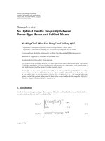
The task of a multipath estimator is to estimate the mul-
tipath delay profile through the use of a modified adaptive
filter, which is illustrated in Figure 4. It employs the tap-delay
line with an Adeline network to create this structure without
a nonlinear element [21, 22]. An adaptive algorithm such as
the LMS algorithm or the backpropagation (BP) learning al-
gorithm is often utilized to adjust the weights of the Adaline
so that it responds accurately to as many patterns as pos-
sible in a training set. In this paper, the BP with an adap-
tive learning rate algorithm is utilized as a substitute for the
LMS algorithm. This is to avoid inherent limitations in the
LMS and to improve filter convergence rate [23]. Thus, the
BP is the simplest self-learning algorithm that adapts itself to
achieve an optimal solution [24, 25]. The multipath estima-
tor mainly provides the multipath delay profile. This utilizes
reference signals in the estimation process. A reference sig-
nal is a replica of code and carrier obtained from the output
of the DLL and the PLL and is mathematically expressed as
follows:
x
i
(n) = g
n − iτ
d
− τ
err
cos
ωn − ϕ
err
(i = 0, , K),
(2)
where τ
err
and ϕ
err
are the measured group delay and carrier
phase that includes multipath error. τ
d
is the sample period
of the delay of the multipath signals and Kτ
d
is the maximum
delay of multipath signals. It is assumed that the estimated
digital IF signal can be defined as
y(n) =
M
i=0
A
i
g(n − τ
i
)cos(ωn + ϕ
i
)+η(n), (3)
where the parameter with the symbol “
∼” denoted the esti-
mated parameter. Because the parameters are impossible to
be determined directly without any assumption about mul-
tipath signals, we employ (2) in estimation process. Thus,
(3) is modified by using the reference signal and replacing
M with
K, the output signal of the filter is given by
y(n) =
K
i=0
w
i
x
i
(n)+w
b
x
b
+ η(n), (4)
where w
i
=
A
i
cos( − ϕ
i
) is the adjustable weight. The filter
weight is used to minimize the cost function, which is also
called the squared error energy function and is defined by
using (1)and(3):
L(n)
=
y(n) − y(n)
2
. (5)
The filter that minimizes the cost function must be chosen
by its tap weights to be the optimal solution to the normal
equation [26],
Cw
opt
= p,(6)
where C is the autocorrelation, E[x
l
(n)x
H
i
(n)], of two ref-
erence signals (x
l
(n)andx
i
(n)). p is the crosscorrelation,
E[y(n)x
H
l
(n)], of the digital IF signal y(n) and reference sig-
nal x
l
(n). Where E[·] is an expectation operator, the filter
solves (6) recursively by using the BP with the adaptive learn-
ing rate algorithm. This learning rule performs a gradient de-
scent on the energy function in order to achieve a minimum
w
i
(n +1)= w
i
(n) − μ
∂L(n)
∂w
i
(n)
,
w
b
(n +1)= w
b
(n) − μ
∂L(n)
∂w
b
(n)
.
(7)
The learning rate coefficient μ determines stability and con-
vergence rate; and a BP trained reference signal is utilized in
order to obtain the minimum of (5) (see, e.g., [27–29]). If
the learning rate is too large, the search path will oscillate
about the desired path and converge more slowly than a di-
rect descent. However, the descent will progress in small steps
if the learning rate is too small, which significantly increases
the total time to convergence. Thus, an adaptive coefficient
in which the value of μ is a function of the error derivation is
utilized as the solution [25]. To simplify the laws used in the
filter computation, the following is updated:
w
i
(n +1)= w
i
(n)+με(n)x
i
(n),
w
b
(n +1)= w
b
(n)+με(n)x
b
,
(8)
where ε(n) is the output layer error term.
A
i
, ϕ
i
,andτ
i
are es-
timated as the absolute value of weight
|w
i
|, the phase angle
of weight arg(w
i
), and the value of delay element iτ
d
.Thebias
weight w
b
, which is connected to a constant input x
b
= +1,
effectively controls the input signal level of the filter. The dig-
ital IF signal given in (1) is used as the desired signal; and the
output of the DLL and the PLL is utilized as the filter in-
put signal. The reference signal is determined by (2)which
C L. Chang and J C. Juang 5
x
i
(n)
Back-propagation
algorithm
Reference signal
cos(ωn
− ϕ
err
)
Output
of PLL
g(n
− τ
err
)
Output
of DLL
Delay element
Output
signal
y
0
(n)
Digital
IF signal
y(n)
x
b
= +1 Bias input
Update weight
ε(n)
τ
d
τ
d
τ
d
τ
d
w
0
w
1
w
2
w
k
.
.
.
w
b
+
+
+
+
+
−
Figure 4: Structure of the modified adaptive filter used in the multipath estimator.
generates the output of each delay element. Thus, the esti-
mated delay parameters from the filter weights and the delay
element can be obtained, if the learning algorithm has con-
verged.
3.3. Correlation value decomposer
After proceeding with the adaptive filter, the estimated pa-
rameters can be obtained and the correlation decomposer
divides the estimated parameters into multipath and direct
signal. In addition, the autocorrelation function of multipath
signals is subtracted from analog-to-digital (A/D) converter
output of the received signal. In the decomposer process, it is
assumed that the values of the first peak amplitude tap weight
are the direct signal and the remainders are multipath signals.
Figure 5 shows an example in which the direct signal refers to
the first peak i
= l and the multipath signal amplitude as the
remnants l<i
≤ K. It is assumed that the multipath chan-
nel has a decreasing power delay profile. Finally, the multi-
path signal parameter is then used to calculate the correla-
tion value. The correlation equation of estimated multipath
signalswithamplitude
A
i
,delayτ
i
, and carrier phase ϕ
i
is
given by
C
i
(τ) =
A
i
C
τ − τ
i
cos
ϕ
l
− ϕ
i
,(9)
where C(τ) is the autocorrelation function, E[g(n)g(n
− τ)],
of the GPS pseudorandom noise (PRN) code signal. Thus,
the entire correlation value of the estimated multipath signal
C
i
(τ)iswrittenas
C
p
(τ) = C
l+1
(τ)+C
l+2
(τ)+··· + C
K
(τ)
=
k
i=l+1
C
i
(τ).
(10)
−0.4
−0.2
0
0.2
0.4
0.6
0.8
1
1.2
Amplitude
0 5 10 15 20 25
Delay element (no.)
Multipath signals
Direct signal
Figure 5: Decomposition of estimated parameters divided into di-
rect signal and multipath signal. (The first peak is the direct signal
and the others are multipath signals.)
3.4. Multipath removal
The entire correlation values of multipath signal C
p
are sub-
tracted from the correlation value of received signal C
r
and
the output of correlation value C
d
is given by
C
d
(τ) = C
r
(τ) − C
p
(τ). (11)
The tracking error occurred in the DLL and the PLL because
of the multipath effect. The effect principally comes from the
distortion of the correlation function receiving the IF signal,
as shown in Figure 6. The figure shows the normalized corre-
lation function with multipath effect. It is observed that the
symmetry is lost and that the propagation delay is difficult
to estimate. Therefore, the range measurement accuracy is
6 EURASIP Journal on Advances in Signal Processing
0
0.2
0.4
0.6
0.8
1
1.2
1.4
Normalized correlation value
Code delay (chips)
Multipath
Direct only
Direct plus multipath
Correlation function
of received signal C
r
(τ)
Correlation function
of estimated multipath
signal C
i
(τ)
Late
Correlation function
of estimated direct
signal
Early
Prompt
DLL tracking error
Figure 6: Normalized correlation functions, with and without mul-
tipath, respectively (plot in phase).
diminished. However, using a subtractive method provides
multipath mitigation in the tracking loop and the output
C
p
(τ) enables the tracking loop to track direct signal accu-
rately.
The above processes, the estimating process, the correla-
tion decomposer, and the cancellation method, can reduce
the multipath effects concerning the autocorrelation func-
tion of the received signal since the tracking errors in DLL
and PLL are not completely removed. Given that the refer-
ence signal acquires the multipath error, the estimated pa-
rameters do not reflect correctly that of the real multipath.
In order to achieve the ideal estimated parameters, the BP
learning process is recursively utilized.
4. PERFORMANCE ANALYSIS AND
SIMULATION RESULTS
In this section, computer simulations are conducted to assess
the performance of the proposed method. To make an easy
comparison in performance with other published methods,
the multipath tracking error envelopes in code and carrier
phase for a multipath signal amplitude of half the LOS am-
plitude are represented as A
0
= 1.0andA
1
= 0.5. A GPS
multipath model consists of one direct signal and one de-
layed signal. It is assumed that a high signal-to-noise ratio
(SNR) of 10 dB is located in this model. Simulation results
are demonstrated in infinite bandwidth situation.
4.1. Simulation parameter
The digital IF frequency of a GPS signal is ω/2π
= 1.25 MHz
and the sampling rate is 5 MHz. The delay chip of the multi-
path signal is varied from 0 to 1.5 chips with the phase of 0
and π radians relating to the direct signal. In conventional
−0.2
−0.1
0
0.1
0.2
0.3
0.4
0.5
0.6
Carrier phase error (rads)
00.25 0.50.75 1 1.25 1.5
Code delay (chips)
Multipath phase error envelopes
(Adaptive multipath
estimator, 90 deg)
τ
d
= 0.5 chip
τ
d
= 0.1 chip
τ
d
= 0.01 chip
MEDLL
Enhance strobe correlator, 90 deg
Narrow, edge, and strobe correlator, 90 deg
Conventional correlator, 90 deg
Figure 7: Carrier-phase error simulation results. (A
0
= 1.0, A
1
=
0.5, τ
0
= 0 chip, τ
1
= 0∼1.5 chip, φ
0
= 0
◦
, φ
1
= 90
◦
; delay ele-
ment τ
d
= 0.01 chip, 0.1 chip, and 0.5 chip is compared with other
existing methods.)
correlator simulations, code-phase error and carrier-phase
error are computed with 1 chip of an early-late discriminator.
The chip spacing of a narrow correlator is less than 1 chip.
Usually, a spacing of 0.2 chips is used to build up the discrim-
inator functions. Two different narrow correlator discrimi-
nators are employed in a strobe correlator and the chip spac-
ing of the two narrow correlators can be adjusted to 0.1and
0.2 chips. The same parameters are also utilized in both en-
hanced strobe and edge correlators. The E1/E2 tracker of the
two correlators is located at E1
= −0.55 and E2 = −0.45 with
0.1 chip spacing [16]. The modified adaptive filter method
under the parameter of tap delay τ
d
= 0.01 chip, 0.1chip,
0.5 chip and its 5-delayed tap are used as the input to the fil-
ter. The initial learning rate is 0.05, the number of training
samples is 5000 at 1 ms C/A code period and the weights are
initialized to 1. The performance is evaluated on a separate
test set of 100 ms samples measured at intervals of 1 ms sam-
ples during the adaptive process.
4.2. Performance comparison
The multipath performance of these correlation techniques
will be compared with each other, including the proposed
method of this paper. To achieve this, the envelopes of all
techniques described above are plotted into the same dia-
gram to allow for a comprehensive comparison of multipath
mitigation performance.
Figures 7–9 compare the error envelopes of the code
phase and carrier phase for all of the multipath mitigation
techniques considered. Simulation results show that the pro-
posed method for the τ
d
= 0.01 chip case has both the best
overall code multipath and the best carrier multipath per-
formance. The conventional PLL has a maximum 0.52 radi-
ans in carrier-phase error. Therefore, the use of the conven-
tional correlator results in very large maximum multipath er-
rors and shows the worst multipath performance. The same
C L. Chang and J C. Juang 7
−0.1
−0.08
−0.06
−0.04
−0.02
0
0.02
0.04
0.06
0.08
0.1
Ranging error (chip)
00.511.5
Code delay (chip)
Code multipath tracking errors envelopes (phase 0, 180 deg)
(Adaptive multipath
estimator, 0 deg)
τ
d
= 0.01 chip
τ
d
= 0.1 chip
τ
d
= 0.5 chip
(Adaptive multipath
estimator, 180 deg)
τ
d
= 0.01 chip
τ
d
= 0.1 chip
τ
d
= 0.5 chip
Figure 8: Code-phase error simulation results of proposed method.
(A
0
= 1.0, A
1
= 0.5, τ
0
= 0 chip, τ
1
= 0∼1.5 chip, φ
0
= 0
◦
, φ
1
=
0
◦
, 180
◦
; delay element τ
d
= 0.01 chip, 0.1 chip, and 0.5 chip.)
−0.1
−0.08
−0.06
−0.04
−0.02
0
0.02
0.04
0.06
0.08
0.1
Ranging error (chip)
00.511.5
Code delay (chip)
Code multipath tracking errors envelopes (phase 0, 180 deg)
MEDLL
Narrow
correlator
Edge
correlator
Enhance strobe
correlator
Conventional
correlator
Strobe
correlator
E1/E2
correlator
Figure 9: Code-phase error simulation results of existing methods.
(Conventional correlator, edge, E1/E2, narrow, strobe, enhanced
strobe, and MEDLL correlator;A
0
= 1.0, A
1
= 0.5, τ
0
= 0 chip,
τ
1
= 0∼1.5 chip, φ
0
= 0
◦
, φ
1
= 0
◦
, 180
◦
.)
results are in both narrow and edge correlators. It must be
taken into consideration that since the narrow, the MEDLL,
and the edge and strobe correlators do not offer any carrier-
phase elimination, their sensitivity to multipath is almost the
same as the one-chip conventional correlator. Only slight dif-
ferences can be observed on account of differences in their
code multipath mitigation.
From these figures through the use of the proposed
method with a delay element τ
d
= 0.01 chip, both code-
and carrier-phase errors are reduced in the range of delay
from 0 through 1.5 chip. In contrast, through the adoption
of the proposed multipath mitigation approach with a tap
delay τ
d
= 0.01, the code- and carrier-phase error decrease
dramatically in the range of delay from 0 to 1.5 chip. In the
case of the tap delay τ
d
= 0.1, multipath mitigation perfor-
mance degrades in comparison with the case of τ
d
= 0.01.
This is due to the accuracy of the estimated delay profile in
0
0.5
1
1.5
Multipath delay (chip)
12345678910
Iteration time
True multipath delay
Adaptive multipath estimator τ
d
= 0.01
Adaptive multipath estimator τ
d
= 0.1
MEDLL
Figure 10: Delay estimated by MEDLL and adaptive multipath es-
timator.
0
0.2
0.4
0.6
0.8
1
Estimated amplitude
−2
−1.5
−1
−0.5
0
0.5
1
1.5
2
Code delay (chip)
0
2
4
6
8
10
Iteration times
τ
0
= 0chip,
A
0
= 1, φ
0
= 0
τ
1
= 0.75 chip,
A
1
= 0.5, φ
0
= 0
Figure 11: An example of estimated parameters. (A
0
= 1.0, A
1
=
0.5, τ
0
= 0, τ
1
= 0.75, φ
0
= 0
◦
, τ
d
= 0.01.)
the adaptive filter relying on the tap delay τ
d
. The smaller τ
d
is, the better the performance of multipath mitigation will
be. In the case of the τ
d
= 0.5 chip, the multipath mitiga-
tion performance degrades in code-phase error simulation
and the carrier-phase error also exceeds that of the conven-
tional tracking loop. Though the use of a small tap delay is
suitable to achieve high performance in multipath mitiga-
tion, it also takes high computation cost to estimate delay
profiles. Thus, there is a tradeoff between the performance of
multipath mitigation and computational load.
Another focal point is that the proposed method
(Figure 8) can better enhance the performance in short-delay
multipath scenario as opposed to almost every DLL structure
(Figure 9). If a given application involves only the short-delay
multipath, then the best correlation techniques such as the
enhanced strobe correlator will not perform any better than
the proposed method of this paper.
8 EURASIP Journal on Advances in Signal Processing
Table 1: Comparative performance of multipath mitigation techniques.
Conventional
correlator
Narrow Strobe
Enhanced
strobe
Edge E1/E2 MEDLL
Modified
adaptive filter
Noise
performance
(SNR
=
−10 dB)
Poor (above
0.2 chip error)
Good
(0.034
chip
error)
Poor
(0.2
∼0.25
chip error)
Poor (below
0.2 chip error)
Fair
(0.054
chip
error)
Fair
(0.04
∼0.06
chip error)
Fair
(below
0.18 chip
error)
Fair (0.05
∼0.1
chip error)
Code
multipath
performance
Poor Fair Fair Good Fair Good Good Best
Carrier
multipath
performance
Poor Poor Poor Fair Poor Poor Good
Best (count on
number τ
d
)
Short-delay
multipath
performance
Poor Poor Poor Fair Poor Good Good Best
Apriori
information
Needed
(coarse delay)
Needed
(coarse
delay)
Needed
(coarse
delay)
Needed
(coarse delay)
Needed
(coarse
delay)
Needed
(coarse
delay)
Needed
(ref-
erence
function)
None
Hardware
complexity
Easy Easy Fair Fair Fair Fair High
Fair (count on
number of
iteration)
Software
complexity
Easy Easy Easy High Fair Easy Fair
Low to
moderate
In order to achieve the estimated performance in the pro-
posed method, the desired multipath correct delay profiles
are A
0
= 1.0, A
1
= 0.5, τ
0
= 0, τ
1
= 0.75, φ
0
= 0
◦
,and
φ
1
= 0
◦
. The delay element number is five. An estimated
multipath delay versus the true multipath delay curve for two
considered algorithms, the MEDLL and the modified adap-
tive filter, is shown in Figure 10. As determined, the proposed
method of τ
d
= 0.01 has faster convergence rate than the
MEDLL. The modified adaptive filter is rapid in convergence
rate with τ
d
= 0.1. However, it is subject to a steady state
error of 0.03 chips in delayed estimation.
Figure 11 shows how the estimate improves over time.
The estimated parameters are computed from 1 to 10 times
with multipath mitigation iteration. The time of iteration is
5 ms. As observed, during the first iteration time, the delay
parameters have a large estimated error caused by the mul-
tipath error of the reference signal. When the iteration time
increases to 5 or 6 ms, the estimated error is reduced and the
correct estimated delay profiles are obtained. The same result
is observed in all simulations.
Ta ble 1 shows the evaluation of these architectures such
as: noise performance, code versus carrier performance, a
priori information needed as an input, short-delay perfor-
mance and hardware/software complexity. With regard to the
noise mitigation performance, when SNR
= −10 dB, the sim-
ulation result shows that the narrow correlator is the best
in performance with the code tracking error of about 0.034
chip. The proposed method in this paper is medium in per-
formance with the tracking error of around 0.05
∼0.1chip,
which is equal to the medium noise performance of the edge
and E1/E2 correlator. In contrast, the conventional correla-
tor, strobe, enhanced strobe correlator, and the MEDLL are
inferior in noise performance, with the tracking error around
0.2 chips.
Regarding the GPS mobile applications, very good accu-
racy is needed even at the expense of slightly increased com-
plexity. In this context, the best options are the enhanced
strobe correlator and the modified adaptive filter. The modi-
fied adaptive filter method has the best performance in mul-
tipath mitigation. However, its hardware complexity, such as
the number of the required multiplications per delay esti-
mate is on the order of O[N
iter
(Kτ
d
)
3
]. Where N
iter
is the
number of filter iterations and Kτ
d
is an estimate of the max-
imum delay spread of the channel in the samples. The high
complexity of this method is principally due to the matrix
inversion operations. However, in short-delay multipath en-
vironments, the number of delay samples Kτ
d
is smaller and
therefore the complexity of the modified adaptive filter is not
very high. The enhanced strobe correlator has lower com-
plexity on the order of O[(Kτ
d
)
2
],butitsperformanceisnot
as good as the modified adaptive filter performance. From
the design point of view, the best tradeoff between accuracy
and complexity should be chosen according to the estimated
maximum delay spread of the channel.
4.3. Brief summary
As indicated previously, there are inherent limitations in al-
most every technique. The combined characteristics of these
studies proposed method prevail over those of other tech-
niques. In addition, the prerequisite of short-delay multipath
C L. Chang and J C. Juang 9
causes the influences of hardware complexity in the mod-
ified adaptive filter to be insignificant. Therefore, the pro-
posed method is a well-suited and well-balanced application
in multipath mitigation.
5. CONCLUSION
Multipath is the dominant error source in high precision-
based GPS applications and is also a significant error source
in nondifferential applications. Many receiver architectures
have been on the market and claim various multipath miti-
gation characteristics. Most of these techniques can be char-
acterized either as discriminator function shaping or correla-
tion function shaping. In this study, a modified adaptive filter
method is applied in multipath mitigation for GNSS applica-
tion. A simplified GPS plus multipath signal model is utilized
in this simulation. This approach improves the performance
of the code-phase and carrier-phase errors compared with all
other published methods. Simulation results also show that
the proposed method is a viable solution to increase the po-
sitional accuracy for GNSS navigation in the presence of a
short-delay multipath environment.
ACKNOWLEDGMENT
The authors would like to thank the National Science Council
of Taiwan for their support of this work under NSC 96-2628-
E-006-246-MY2.
REFERENCES
[1]L.L.Hagerman,“Effects of multipath on coherent and non-
coherent PRN ranging receiver,” Aerospace Report TOR-0073
(3020-03)-3, The Aerospace Corporation, Development Plan-
ning Division, Los Angeles, Calif, USA, 1973.
[2] J. J. Spilker Jr., “GPS signal structure and performance charac-
teristics,” Journal of the Institute of Navigation, vol. 25, no. 2,
pp. 121–146, 1978.
[3] A. J. van Dierendonck, P. J. Fenton, and T. J. Ford, “Theory and
performance of narrow correlator spacing in a GPS receiver,”
Journal of the Institute of Navigation, vol. 39, no. 3, pp. 265–
283, 1992.
[4] D. J. R. van Nee, “Reducing multipath tracking errors in
spread-spectrum ranging systems,” Electronics Lette rs, vol. 28,
no. 8, pp. 729–731, 1992.
[5] R. D. J. van Nee, “Spread-spectrum code and carrier synchro-
nization errors caused by multipath and interference,” IEEE
Transactions on Aerospace and Electronic Systems, vol. 29, no. 4,
pp. 1359–1365, 1993.
[6] M. S. Braasch, “Isolation of GPS multipath and receiver track-
ing errors,” Journal of the Institute of Navigation, vol. 41, no. 4,
pp. 415–434, 1994.
[7] B. R. Townsend and P. C. Fenton, “A practical approach to
the reduction of pseudorange multipath errors in all GPS re-
ceiver,” in Proceedings of the 7th International Technical Meet-
ing of the Satellite Division of the Institute of Navigation (ION-
GPS ’94), vol. 1, pp. 143–148, Salt Lake City, Utah, USA,
September 1994.
[8] R. D. J. van Nee, J. Siereveld, P. C. Fenton, and B. R. Townsend,
“The multipath estimating delay lock loop: approaching the-
oretical accuracy limits,” in Proceedings of the IEEE Position
Location and Navigation Symposium, pp. 246–251, Las Vegas,
Nev, USA, April 1994.
[9]B.R.Townsend,R.D.J.vanNee,P.C.Fenton,andK.J.V.
Dierendonck, “Performance evaluation of the multipath es-
timating delay lock loop,” in Proceedings of the Annual Na-
tional Technical Meeting of the Institute of Navigation (ION-
NTM ’95), pp. 277–283, Anaheim, Calif, USA, January 1995.
[10] L. Garin, F. van Diggelen, and J. Rousseau, “Strobe and edge
correlator multipath rejection for code,” in Proceedings of the
International Technical Meeting of the Institute of Navigation
(ION-GPS ’96), pp. 657 –664, Kansas City, Mo, USA, Septem-
ber 1996.
[11] L. Garin and J. Rousseau, “Enhanced strobe correlator multi-
path rejection for code & carrier,” in Proceedings of the Inter-
national Technical Meeting of the Institute of Navigat ion (ION-
GPS ’97), vol. 1, pp. 559–568, Kansas City, Mo, USA, Septem-
ber 1997.
[12] M. C. Laxton and S. L. DeVilbiss, “GPS multipath mitigation
during code tracking,” in Proceedings of the American Control
Conference (ACC ’97), vol. 3, pp. 1429–1433, Albuquerque,
NM, USA, June 1997.
[13] A. J. van Dierendonck and M. S. Braasch, “Evaluation of
GNSS receiver correlation processing techniques for multipath
and noise mitigation,” in Proceedings of the National Techni-
cal Meeting of the Institute of Navigation (ION-NTM ’99),pp.
207–215, Santa Monica, Calif, USA, January 1997.
[14] M. S. Braasch, “Performance comparison of multipath mit-
igating receiver architectures,” in Proceedings of the IEEE
Aerospace Conference, vol. 3, pp. 1309–1315, Big Sky, Mont,
USA, March 2001.
[15] R. Chaggara, C. Macabiau, and E. Chatre, “Using GPS mul-
ticorrelator receivers for multipath parameters estimation,” in
Proceedings of the International Technical Meeting of the Insti-
tute of Navigation (ION-GPS ’02), pp. 477–486, Portland, Ore,
USA, September 2002.
[16] M. Irsigler and B. Eissfeller, “Comparison of multipath mit-
igation techniques with consideration of future signal struc-
tures,” in Proceedings of the International Technical Meeting of
the Institute of Navigation (ION-GPS/GNSS ’03), pp. 2584–
2592, Portland, Ore, USA, September 2003.
[17] T. Pany, M. Irsigler, and B. Eissfeller, “S-curve shaping: a
new method for optimum discriminator based code multi-
path mitigation,” in Proceedings of the International Techni-
cal Meeting of the Institute of Navigation (ION-GPS/GNSS’05),
vol. 2005, pp. 2139–2154, Long Beach, Calif, USA, September
2005.
[18] J. M. Kelly, M. S. Braasch, and M. F. DiBenedetto, “Charac-
terization of the effects of high multipath phase rates in GPS,”
GPS Solutions, vol. 7, no. 1, pp. 5–15, 2003.
[19] S. K. Kalyanaraman, M. S. Braasch, and J. M. Kelly, “Code
tracking architecture influence on GPS carrier multipath,”
IEEE Transactions on Aerospace and Electronic Systems, vol. 42,
no. 2, pp. 548–561, 2006.
[20] M. S. Braasch and F. van Graas, “Guidance accuracy consid-
erations for real time GPS interferometry,” in Proceedings of
the International Technical Meeting of the Institute of Naviga-
tion (ION-GPS ’91), pp. 373–386, Albuquerque, NM, USA,
September 1991.
[21] B. Widrow and M. E. Hoff, “Adaptive switch circuits,” in IRE
WESCON Convention Record, vol. 55, part 4, pp. 96–104, New
York, NY, USA, 1960.
[22] B. Widrow and M. A. Lehr, “30 years of adaptive neural net-
works: perceptron, madaline, and back propagation,” Proceed-
ings of the IEEE, vol. 78, no. 9, pp. 1415–1442, 1990.
10 EURASIP Journal on Advances in Signal Processing
[23] R. J. Schalkoff, Artificial Neural Networks, McGraw-Hill, New
York, NY, USA, 1997.
[24] D. E. Rumelhart, G. E. Hinton, and R. J. Williams, “Learning
internal representations by error propagation,” in Parallel Dis-
tributed Processing: Explorations and Microstructures of Cogni-
tion, vol. 1, pp. 318–362, MIT press, Cambridge, Mass, USA,
1986.
[25] S. Haykin, Neural Networks: A Comprehensive Foundation,
Prentice Hall, Englewood Cliffs, NJ, USA, 1999.
[26] S. Haykin, Adaptive Filter Theory, Prentice Hall, Englewood
Cliffs, NJ, USA, 1995.
[27] B. Widrow and S. D. Stearns, Adaptive Signal Processing,Pren-
tice Hall, Englewood Cliffs, NJ, USA, 1985.
[28] R. A. Jacobs, “Increased rates of convergence through learning
rate adaptation,” Neural Networks, vol. 1, no. 4, pp. 295–307,
1988.
[29] D. P. Mandic and J. A. Chambers, “Towards the optimal
learning rate for backpropagation,” Neural Processing Letters,
vol. 11, no. 1, pp. 1–5, 2000.