Báo cáo hóa học: " Research Article Distributed Cooperative Transmission with Unreliable and Untrustworthy Relay Channels" docx
Bạn đang xem bản rút gọn của tài liệu. Xem và tải ngay bản đầy đủ của tài liệu tại đây (847.99 KB, 13 trang )
Hindawi Publishing Corporation
EURASIP Journal on Wireless Communications and Networking
Volume 2009, Article ID 740912, 13 pages
doi:10.1155/2009/740912
Research Article
Distributed Cooperative Transmission wi th Unreliable and
Untrustworthy Relay Channels
Zhu Han
1
and Yan Lindsay Sun
2
1
Electrical and Computer Engineering Department, University of Houston, Houston, TX 77004, USA
2
Electrical and Computer Engineering Department, The University of Rhode Island, Kingston, RI 02881, USA
Correspondence should be addressed to Zhu Han,
Received 25 January 2009; Revised 13 July 2009; Accepted 12 September 2009
Recommended by Hui Chen
Cooperative transmission is an emerging wireless communication technique that improves wireless channel capacity through
multiuser cooperation in the physical layer. It is expected to have a profound impact on network performance and design. However,
cooperative transmission can be vulnerable to selfish behaviors and malicious attacks, especially in its current design. In this
paper, we investigate two fundamental questions Does cooperative transmission provide new opportunities to malicious parties
to undermine the network performance? Are there new ways to defend wireless networks through physical layer cooperation?
Particularly, we study the security vulnerabilities of the traditional cooperative transmission schemes and show the performance
degradation resulting from the misbehaviors of relay nodes. Then, we design a trust-assisted cooperative scheme that can detect
attacks and has self-healing capability. The proposed scheme performs much better than the traditional schemes when there are
malicious/selfish nodes or severe channel estimation errors. Finally, we investigate the advantage of cooperative transmission in
terms of defending against jamming attacks. A reduction in link outage probability is achieved.
Copyright © 2009 Z. Han and Y. L. Sun. This is an open access article distributed under the Creative Commons Attribution
License, which permits unrestricted use, distribution, and reproduction in any medium, provided the original work is properly
cited.
1. Introduction
Multiple antenna systems, such as Multiple-Input-Multiple-
Output (MIMO), can create spatial diversity by taking
advantage of multiple antennas and significantly increase the
wireless channel capacity. However, installation of multiple
antennas on one wireless device faces many practical obsta-
cles, such as the cost and size of wireless devices. Recently,
cooperative transmission has gained considerable research
attention as a transmit strategy for future wireless networks.
Instead of relying on the installation of multiple antennas on
one wireless device, cooperative transmission achieves spatial
diversity through physical layer cooperation.
In cooperative transmission, when the source node
transmits a message to the destination node, the nearby
nodes that overhear this transmission will “help” the source
and destination by relaying the replicas of the message,
and the destination will combine the multiple received
waveforms so as to improve the link quality. In other words,
cooperative transmission utilizes the nearby nodes as virtual
antennas and mimics the effects of MIMO for achieving
spatial diversity. It is well documented that cooperative
transmission improves channel capacity significantly and
has a great potential to improve wireless network capacity
[1, 2]. The research community is integrating cooperative
transmission into cellular, WiMAX, WiFi, Bluetooth, ultra-
wideband (UWB), ad hoc, and sensor networks. Cooperative
transmission is also making its way into standards; for
example, IEEE WiMAX standards body for future broadband
wireless access has established the 802.16j Relay Task Group
to incorporate cooperative relaying mechanisms [3].
The majority of work on cooperative transmission
focuses on communication efficiency, including capacity
analysis, protocol design, power control, relay selection, and
cross layer optimization. In those studies, all network nodes
are assumed to be trustworthy. Security threats are rarely
taken into consideration.
(i) It is well known that malicious nodes can enter many
wireless networks due to imperfectness of access
control or through node compromising attack. In
cooperative transmission, the malicious nodes have
2 EURASIP Journal on Wireless Communications and Networking
chances to serve as relays (i.e., the nodes help the
source node by forwarding messages). Instead of
forwarding correct information, malicious relays can
send arbitrary information to the destination.
(i) Cooperative transmission can also suffer from selfish
behavior. When the wireless nodes do not belong
to the same authority, some nodes can refuse to
cooperate with others, that is, not working as relay
nodes, for the purpose of saving their own resources.
(i) In cooperative transmission, channel information is
often required to perform signal combination [1–
3] and relay selection [4–7] at the destination. The
malicious relays can provide false channel state infor-
mation, hoping that the destination will combine the
received messages inadequately.
This paper is dedicated to studying the security issues
related to cooperative transmission for wireless commu-
nications. Particularly, we will first discuss the vulnera-
bilities of cooperative transmission schemes and evaluate
potential network performance degradation due to these
vulnerabilities. Then, we propose a distributed trust-assisted
cooperative transmission scheme, which strengthens security
of cooperative transmission through joint trust management
and channel estimation.
Instead of using traditional signal-to-noise ratio (SNR)
or bit-error-rate (BER) to represent the quality of relay
channels, we construct the trust values that represent
possible misbehavior of relays based on beta-function trust
models [8, 9]. We then extend the existing trust models to
address trust propagation through relay nodes. A distributed
trust established scheme is developed. With a low overhead,
the model parameters can propagate through a complicated
cooperative relaying topology from the source to the desti-
nation. In the destination, the information from both the
direct transmission and relayed transmissions is combined
according to the trust-based link quality representation.
From analysis and simulations, we will show that the
proposed scheme can automatically recover from various
attacks and perform better than the traditional scheme with
maximal ratio combining. Finally, we investigate possible
advantages of utilizing cooperation transmission to improve
security in a case study of defending against jamming attacks.
The rest of the paper is organized as follows. Related
work is discussed in Section 2.InSection 3, the system model
and attack models are introduced. In Section 4, the proposed
algorithms are developed. Finally, simulation results and
conclusions are given in Sections 5 and 6,respectively.
2. Related Work
Research on cooperative transmission traditionally focuses
on efficiency. There is a significant amount of work devoted
to analyzing the performance gain of cooperative transmis-
sion, to realistic implementation under practical constraints,
to relay selection and power control, to integrating physical
layer cooperation and routing protocols, and to game-
theory-based distributed resource allocation in cooperative
transmission. For example, the work in [4] evaluates the
cooperative diversity performance when the best relay is
chosen according to the average SNR and analyzes the
outage probability of relay selection based on instantaneous
SNRs. In [5], the authors propose a distributed relay selec-
tion scheme that requires limited network knowledge with
instantaneous SNRs. In [6], cooperative resource allocation
for OFDM is studied. A game theoretic approach for relay
selection has been proposed in [7]. In [10], cooperative
transmission is used in sensor networks to find extra paths
in order to improve network lifetime. In [11], cooperative
game theory and cooperative transmission are used for
packet forwarding networks with selfish nodes. In [12],
centralized power allocation schemes are presented under
the assumption that all the relay nodes help others. In
[13], cooperative routing protocols are constructed based on
noncooperative routes. In [14], a contention-based oppor-
tunistic feedback technique is proposed for relay selection in
dense wireless networks. In [15], the users form coalitions
of cooperation and use MIMO transmission. Traditional
cooperative transmission schemes, however, assume that all
participating nodes are trustworthy.
Trust establishment has been recognized as a powerful
tool to enhance security in applications that need coop-
eration among multiple distributed entities. Research on
trust establishment has been performed for various applica-
tions, including authorization and access control, electronic
commerce, peer-to-peer networks, routing in MANET, and
data aggregation in sensor networks [8, 16–20]. As far as
the authors’ knowledge, no existing work on trust is for
cooperative transmission. In fact, not much study on trust
has been conducted for physical layer security.
3. System Model, Attack Models, and
Requirements on Defense
In this section, we first describe the cooperative transmission
system model, then investigate the different attack models,
and finally discuss the general requirements on the design of
defense mechanisms.
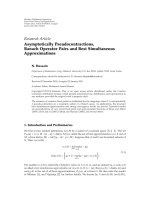
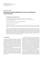
3.1. Cooperative Transmission Syste m. As shown in Figure 1,
the system investigated in this paper contains a source node s,
some relay nodes r
i
, and a destination node d. The relays can
form single hop or multihop cooperation paths. The relay
nodes might be malicious or selfish. We first show a simple
one-hop case in this subsection, and the multihop case will
be discussed in a later section.
Cooperative transmission is conducted in two phases. In
Phase 1,sources broadcasts a message to destination d and
relay nodes r
i
. The received signal y
d
at the destination d and
the received signal y
r
i
at relay r
i
can be expressed as
y
d
=
P
s
G
s,d
h
s,d
x + n
d
,(1)
y
r
i
=
P
s
G
s,r
i
h
s,r
i
x + n
r
i
. (2)
In (1)and(2), P
s
represents the transmit power at the source,
G
s,d
is the path loss between s and d,andG
s,r
i
is the path loss
EURASIP Journal on Wireless Communications and Networking 3
Relay 1
Multihop relay
Relay N
Phase 2: Relay
Phase 1: Broadcast
Source
Relay 2
Relay question: Whether/
when/how to relay
Malicious relay
Destination question:
How to combine two phases
security concern
Destination
One source-relay-destination example
xy
d
y
x
y
r
i
x
r
i
y
r
i
Source
Phase 1
Phase 2 Phase 2
Relay i
Destination
combining
Correlation
Figure 1: Cooperative transmission system model.
between s and r
i
. h
s,d
and h
s,r
i
are fading factors associated
with channel s
− d and channel s − r
i
,respectively.Theyare
modeled as zero mean and unit variance complex Gaussian
random variables. x is the transmitted information symbol
with unit energy. In this paper, without loss of generality,
we assume that BPSK is used and x
∈{0, 1}. n
d
and
n
r
i
are the additive white Gaussian noises (AWGN) at the
destination and the relay nodes, respectively. Without loss
of generality, we assume that the noise power, denoted by
σ
2
, is the same for all the links. We also assume the block-
fading environment, in which the channels are stable over
each transmission frame.
When there is no relay, the transmission only contains
Phase 1 and is referred to as direct transmission. In direct
transmission, without the help from relay nodes, the SNR at
the destination is
Γ
d
=
P
s
G
s,d
E
h
s,d
2
σ
2
. (3)
In Phase 2, relay nodes send information to the destina-
tion at consecutive time slots. After the destination receives
the information from the source node and all relay nodes,
which takes at least N
r
+ 1 time slots where N
r
is the number
of relays, the destination combines the received messages and
decodes data.
We examine the decode-and-forward (DF) cooperative
transmission protocol [1, 2], in which the relays decode
the source information received in Phase 1 and send the
information to the destination in Phase 2. Recall that relay
r
i
receives signal y
r
i
from the source node d.Letx
r
i
denote
the data decoded from y
r
i
.Relayr
i
then reencodes x
r
i
,and
sends it to the destination. Let
y
r
i
denote the received signal
at the destination from relay r
i
.Then,
y
r
i
=
P
r
i
G
r
i
,d
h
r
i
,d
x
r
i
+ n
d
,(4)
where P
r
i
is the transmit power at relay r
i
, G
r
i
,d
is the path
loss between r
i
and d, h
r
i
,d
is the fading factor associated
with channel r
i
− d, which is modeled as zero mean and
unit variance Gaussian random variable, and n
d
is the AWGN
thermal noise with variance σ
2
.
3.2. Attack Models and Requirements on D efense. As dis-
cussed in Section 1, for cooperative transmission, we identify
the following three types of misbehavior.
(i) Selfish Silence. There are selfish nodes that do not
relay messages for others in order to reserve their own
energy.
(ii) Malicious Forwarding. There are malicious nodes that
send garbage information to the destination when
they serve as relays.
(iii) False Feedback. Malicious nodes report false channel
information to make the destination perform signal
combination inadequately.
4 EURASIP Journal on Wireless Communications and Networking
Can security vulnerability in cooperative transmission be
fixed? To answer this question, we take a closer look at the
fundamental reasons causing security vulnerability.
First, cooperation among distributed entities is inheri-
tably vulnerable to selfish and malicious behaviors. When
a network protocol relies on multiple nodes’ collaboration,
the performance of this protocol can be degraded if some
nodes are selfish and refuse to collaborate, and can be
severely damaged if some nodes intentionally behave oppo-
sitely to what they are expected to do. For example, the
routing protocols in mobile ad hoc networks rely on nodes
jointly forwarding packets honestly, and the data aggregation
protocols in sensor networks rely on sensors all reporting
measured data honestly. It is well known that selfish and
malicious behaviors are major threats against the above
protocols. Similarly, since cooperative transmission relies on
collaboration among source, relay and destination nodes, it
can be threatened by selfish and malicious network nodes.
Second, when the decision-making process relies on
feedback information from distributed network entities, this
decision-making process can be undermined by dishonest
feedbacks. This is a universal problem in many systems.
For example, in many wireless resource allocation protocols,
transmission power, bandwidth and data rate can all be
determined based on channel state information obtained
through feedbacks [5, 7, 11]. In cooperative transmission,
the relay selection and signal combination process depend
on channel state information obtained through feedbacks.
Third, from the view point of wireless communica-
tions, traditional representation of channel state information
cannot address misbehavior of network nodes. In most
cooperative transmission schemes, information about relay
channel status is required in relay selection and trans-
mission protocols. However, the traditional channel state
information, either SNR or average BER, only describes the
features of physical wireless channel, but cannot capture the
misbehavior of relay nodes.
The above discussion leads to an understanding on the
primary design goals of the defense mechanism. A defense
mechanism should be able
(i) to provide the distributed network entities a strong
incentive to collaboration, which suppresses selfish
behaviors,
(ii) to detect malicious nodes and hold them responsible,
(iii) to provide the cooperative transmission protocols
with accurate channel information that (a) reflects
both physical channel status as well as prediction on
likelihood of misbehavior and (b) cannot be easily
misled by dishonest feedbacks.
4. Trust-Based Cooperative Tra nsmission
In this section, we first provide basic concepts related to
trust evaluation in Section 4.1. Second, we discuss the key
components in the proposed scheme, including the beta-
function-based link quality representation and link quality
propagation, in Section 4.2. Then, the signal combining
algorithm at the destination is investigated in Section 4.3.
Next, we present the overall system design in Section 4.4,
followed by a discussion on implementation overhead in
Section 4.5.
4.1. Trust Establishment Basic. Trust establishment has been
recognizedasapowerfultooltosecurecollaborationamong
distributed entities. It has been used in a wide range of
applications for its unique advantages.
If network entities can evaluate how much they
trust other network entities and behave accord-
ingly, three advantages can be achieved. First, it
provides an incentive for collaboration because
the network entities that behave selfishly will
have low trust values, which could reduce their
probabilities of receiving services from other
network entities. Second, it can limit the impact
of malicious attacks because the misbehaving
nodes, even before being formally detected, will
have less chance to be selected as collaboration
partners by other honest network nodes. Finally,
it provides a way to detect malicious nodes
according to trust values.
The purpose of trust management matches perfectly with
the requirements for defending cooperative transmission.
Designing a trust establishment method for cooperative
transmission is not an easy task. Although there are many
trust establishment methods in the current literature, most
of them sit in the application layer and few were developed
for physical/MAC layer communication protocols. This is
mainly due to the high implementation overhead. Trust
establishment methods often require monitoring and mes-
sage exchange among distributed nodes. In physical layer,
monitoring and message exchange should be minimized to
reduce overhead. Therefore, our design should rely on the
information that is already available in the physical layer.
While the detailed trust establishment method will
be described in a later section, we introduce some trust
establishment background here.
When node A can observe node B’s behavior, node A
establishes direct trust in node B based on observations. For
example, in the beta-function-based-trust model [9], if node
A observes that node B has behaved well for (α
−1) times and
behaved badly for (β
−1) times, node A calculates the direct
trust value [9]asα/(α + β). The beta-function based trust
model is widely used for networking applications [18, 20],
whereas there are other ways to calculate direct trust mainly
for electronic commerce, peer-to-peer file sharing, and access
control [8, 17].
Trust can also be established through third parties. For
example, if A and B
1
have established a trust relationship
and B
1
and Y have established a trust relationship, then
A can trust Y to a certain degree if B
1
tells A its trust
opinion (i.e., recommendation) about Y. This phenomenon
is called trust propagation. Trust propagation becomes more
complicated when there is more than one trust propagation
path. Through trust propagation, indirect trust can be
EURASIP Journal on Wireless Communications and Networking 5
established. The specific ways to calculate indirect trust
values are determined by trust models [8].
Finally, building trust in distributed networks requires
authentication. That is, one node cannot easily pretend to be
another node in the network.
No matter whether trust mechanism is used or not, the
physical layer control messages need to be authenticated,
when there is a risk of malicious attack. In this work, we
assume that the messages are authenticated in cooperative
transmission using existing techniques [21, 22].
4.2. Trust-Based Representat ion of Link Quality. The beta-
function trust model is often used to calculate whether a
node is trustworthy or not in networking applications. For
example, node B has transmitted (α + β
− 2) packets to
node A. Among them, node A received (α
− 1) packets with
SNR greater than a certain threshold. These transmissions
are considered to be successful. The transmission of other
packets is considered to be failed. That is, there are (α
−
1) successful trials and (β − 1) failed trials. It is often
assumed that the transmission of all (α + β
− 2) packets are
independent and a Bernoulli distribution with parameter p
governs whether the transmissions succeed or fail. (This is
true with ideal interleavers.) Under these assumptions, given
α and β, the parameter p follows a beta distribution as
B
α, β
=
Γ
α + β
Γ
(
α
)
Γ
β
p
α−1
1 − p
β−1
. (5)
It is well known that B(α, β) has mean m and variance v as
m
=
α
α + β
; v
=
αβ
α + β
2
α + β +1
. (6)
In the context of trust establishment, given α and β
values, the trust value is often chosen as the mean of B(α, β),
that is, α/(α + β). This trust value represents how much
a wireless link can be trusted to deliver packe ts correctly.
In addition, some trust models introduce confidence values
[23]. The confidence value is often calculated from the
variance of B(α, β).Theconfidencevaluerepresentshow
much confidence the subject has in the trust value.
Due to the physical meaning of the trust values and the
close tie between trust and the beta function, we use the beta
function to represent the link quality in this paper. This is
equivalent to using trust and confidence values to describe
the link quality.
Since an interleaver is often employed in the transceiver
and noise is independent over time, we can justify that
successful transmission of different packets is independent
if the interleaver is carefully selected to be greater than the
coherence time of the channel. As a result, we justify the use
of the beta distribution. Compared with traditional frame
error rate (FER), BER and SNR, the trust-based link quality
representation has both advantages and disadvantages. As
an advantage, the trust-based link quality can describe the
joint effect of wireless channel condition, channel estimation
error, and misbehavior of relay nodes. On the other hand, the
trust-based link quality cannot describe the rapid changes
in channel conditions because the α and β values need to
be collected over multiple data packets. Thus, it is suitable
for scenarios with slow fading channels or high data rate
transmission, in which channel condition remains stable
over the transmission time of several packets.
4.3. Signal Combination at Destination. In this Section, we
discuss how to utilize trust-based link quality information
in the signal combination process. In Section 4.3.1,we
discuss how the signal is combined at the waveform level. In
Section 4.3.2, we extend our solution to the multihop case.
Finally, we investigate how the proposed solution can defend
against the bad-mouthing attack in Section 4.3.3.
First, from [24], the BER of BPSK in Rayleigh fading can
be given by a function of SNR as
BER
=
1
2
⎛
⎝
1 −
Γ
1+Γ
⎞
⎠
,(7)
where Γ is the SNR. Here FER has one-to-one mapping with
BER as FER
= 1 − (1 − BER )
L
,whereL is the frame
length. (Notice that other modulations can be treated in a
similar way.) So in the rest of paper, we only mention BER.
To simplify analysis, we assume that error control coding is
not used in this paper. The design of the proposed scheme,
however, will not be affected much by coding schemes.
When coding is used, the BER expression in (7) will change.
Depending on different coding systems such as Hamming
code, RS code or convolutional code, the BER performance
would be different. The BER would be reduced at the same
SNR, or in other words, to achieve the same SNR, the
required SNR will be reduced. So the reliability of the links
due to the channel errors can be improved. On the other
hand, coding is a way to improve reliability, but cannot
address untrustworthy nodes. The proposed scheme will
work for both coded and uncoded transmissions.
4.3.1. Waveform Level Combination. In traditional coop-
erative transmission schemes, maximal ratio combining
(MRC) [24] is often used for waveform level combination.
Specifically, for the case of a single-hop relay, remember that
y
d
is the signal received from the direct path and y
i
r
is the
signal received from the relay. Under the assumption that the
relay can decode the source information correctly, the MRC
combined signal with weight factor w
i
is
y
mrc
= w
0
y
d
+
i
w
i
y
i
r
,(8)
where w
0
= 1andw
i
=
P
r
i
G
r
i
,d
/P
s
G
s,d
. The resulting SNR
is given by [24]
Γ
MRC
= Γ
d
+
i
Γ
r
i
,(9)
where Γ
d
= P
s
G
s,d
E[|h
s,d
|
2
]/σ
2
and Γ
r
i
= P
r
i
G
r
i
,d
E[|h
r
i
,d
|
2
]/
σ
2
are SNR of direct transmission and relay transmission,
respectively. When channel decoding errors and nodes’
misbehavior are present, the MRC is not optimal any more.
6 EURASIP Journal on Wireless Communications and Networking
This is because the received signal quality is not only related
to the final link to the destination, but also related to
decoding errors or misbehavior at the relay nodes.
In the proposed scheme, we use the beta function to
capture the channel variation as well as relay misbehavior.
This requires a new waveform combination algorithm that is
suitable for trust-based link quality representation.
We first consider the case of one single-hop relay path.
Depending on whether or not the relay decodes correctly,
using derivation similar to MRC [24], the combined SNR at
the destination for BPSK modulation can be written as
Γ
=
⎧
⎪
⎪
⎪
⎪
⎪
⎪
⎪
⎪
⎪
⎪
⎨
⎪
⎪
⎪
⎪
⎪
⎪
⎪
⎪
⎪
⎪
⎩
Γ
c
=
Γ
d
+ w
2
1
Γ
r
1
+2w
1
Γ
d
Γ
r
1
1+w
2
1
, if the relay decodes
correctly,
Γ
w
=
Γ
d
+ w
2
1
Γ
r
1
−2w
1
Γ
d
Γ
r
1
1+w
2
1
, if the relay decodes
incorrectly.
(10)
If the relay decodes correctly, the relayed signal improves the
final SNR; otherwise, the SNR is reduced. Notice that here
1 is the weight for the direction transmission and w
1
is the
weight for the relay transmission.
Let B(α
1
, β
1
) represent the link quality of the source-
relay channel. We set the goal of signal combination to be
maximizing the SNR at the destination after combination by
finding the optimal weight vector for combination. That is,
w
∗
1
= arg min
w
1
1
0
pΓ
c
+
1 − p
Γ
w
B
α
1
, β
1
dp. (11)
By differentiating the right-hand side of (11), we obtain
the optimal combination weight factor as
w
∗
1
=
Γ
r
1
−Γ
d
+
Γ
2
d
+ Γ
2
r
1
+2
1 − 8m
1
+8m
2
1
Γ
d
Γ
r
1
2
(
2m
1
−1
)
Γ
d
Γ
r
1
, (12)
where m
1
is the mean of the relay’s successful decoding
probability or the mean of B(α
1
, β
1
). Obviously, m
1
=
α
1
/(α
1
+ β
1
).
When the relay decodes perfectly, that is, m
1
= 1, we have
w
∗
1
=
Γ
r
1
Γ
d
, (13)
which is the same as that in MRC. When m
1
= 0.5, we have
zero-divide-zero case in (12). In this case, we define w
∗
1
= 0,
since the relay decodes incorrectly and forwards independent
data. As a result, the weight for the relay should be zero, and
the system degrades to direct transmission only.
For the case of multiple single-hop relay paths, we assume
that each relay has link quality (α
i
, β
i
), SNR Γ
r
i
, and weight
w
i
. Recall that the link quality report from the relay i is
(α
i
, β
i
), where (α
i
− 1) equals to the number of successfully
transmitted packets between the source and relay i and
(β
i
− 1) equals to the number of unsuccessfully transmitted
packets between the source and relay i. The mean of the
beta function for relay i is denoted by m
i
and calculated as
m
i
= α
i
/(α
i
+ β
i
). The overall expected SNR can be written as
Γ
= max
w
i
q
i
∈{−1,1}
i
Q
q
i
, m
i
Γ
d
+
i
q
i
w
i
Γ
r
i
2
1+
i
w
2
i
, (14)
where q
i
indicates whether relay i decodes correctly, and
Q
q
i
, m
i
=
⎧
⎨
⎩
m
i
, q
i
= 1, decode correctly,
1
−m
i
, q
i
=−1, decode incorrectly.
(15)
Equation (14) employs the probability Q(q
i
, m
i
) and con-
ditional SNR in (10). In this case, the optimal w
i
can be
calculated numerically by minimizing (14) over parameter
w
i
. Some numerical methods such as the Newton Method
[25, 26] can be utilized. Note that this optimization problem
may not be convex. Achieving global optimum needs some
methods such as simulated annealing [25, 26].
As a summary, the waveform level combination is
performed in the following four steps.
(i) For each path, the destination calculates m
i
values
based on the relays’ report on their link quality.
(ii) The second is maximizing the SNR (equivalent to
minimizing BER) in (14) to obtain the optimal
weight factors. If there is only one relay path, the
optimal weight factor is given in (12).
(iii) The third step is calculating the combined waveform
y using (8).
(iv) The fourth step is decoding the combined waveform
y.
4.3.2. Extension to Multiple-Hop Relay Scenario. In the
previous discussion, we focus on the one-hop relay case, in
which the relay path is source-relay-destination. Next, we
extend our proposed scheme to multiple such relay paths.
It is noted that the relay path may contain several
concatenated relay nodes. An example of such relay path is
s
−r
a
−r
b
−d,wheres is the source node, d is the destination,
r
a
and r
b
are two concatenated relay nodes. This scenario has
been studied in [27, 28].
To make the proposed scheme suitable for general
cooperative transmission scenarios, we develop an approach
to calculate the link quality through concatenation propaga-
tion. In particular, let B(α
sa
, β
sa
) represent the link quality
between s and r
a
,andB(α
ab
, β
ab
) represent the link quality
between r
a
and r
b
. If we can calculate the link quality between
s and r
b
,denotedbyB(α
sb
, β
sb
), from α
sa
, β
sa
, α
ab
, β
ab
,we
will be able to use the approach developed in Section 4.3.1,
by replacing (α
i
, β
i
)with(α
sb
, β
sb
). Then, (α
i
, β
i
) represents
the link quality of the i
th
relay path, which is s − r
a
− r
b
− d
in this example.
Next, we present the link quality concatenation prop-
agation model for calculating (α
sb
, β
sb
). Let x denote the
probability that transmission will succeed through path
EURASIP Journal on Wireless Communications and Networking 7
s
−r
a
−r
b
. The cumulative distribution function of x can be
written as
CDF
(
x
)
=
x=pq
0
Γ
α
sa
+ β
sa
Γ
α
ab
+ β
ab
Γ
(
α
sa
)
Γ
β
sa
Γ
(
α
ab
)
Γ
β
ab
×
p
α
sa
−1
q
α
ab
−1
1 − p
β
sa
−1
1 − q
β
ab
−1
dpdq.
(16)
Sinceitisverydifficult to obtain the analytical solution
to (16), we find a heuristic solution to approximate the
distribution of x. Three assumptions are made.
First, even though the distribution of the concatenated
signal is not a beta function, we approximate the distribution
of
x as a beta distribution B(α
sb
, β
sb
). Let (m
sa
, v
sa
), (m
ab
, v
ab
),
and (m
sb
, v
sb
) represent the (mean, variance) of distribution
B(α
sa
, β
sa
), B(α
ab
, β
ab
), and B(α
sb
, β
sb
), respectively. The
mean and variance of the beta distribution are given in (6).
Second, we assume m
sb
= m
sa
· m
ab
. Recall that m
sb
, m
sa
and m
ab
represent the probability of successful transmission
along path s
− r
b
, s − r
a
,andr
a
− r
b
, respectively. When the
path is s
− r
a
− r
b
, the packets are successfully transmitted
from s to r
b
only if the packets are successfully transmitted
from s to r
a
and from r
a
to r
b
.
Third, we assume v
sa
+ v
ab
= v
sb
. The third assumption
means that the noises added by two concatenated links are
independent and their variances can be added together.
With the above assumptions, we can derive that
α
sb
= m
sa
m
ab
m
sa
m
ab
(
1
−m
sa
m
ab
)
v
sa
+ v
ab
−1
,
β
sb
=
(
1
−m
sa
m
ab
)
m
sa
m
ab
(
1
−m
sa
m
ab
)
v
sa
+ v
ab
−1
.
(17)
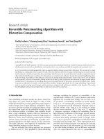
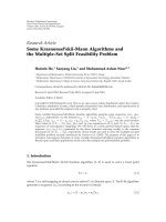
In order to validate the accuracy of the proposed approx-
imation, we have examined a large number of numerical
examples by varying α and β. We have seen that the proposed
heuristic approximation is a good fit. One such example is
illustrated in Figure 2, which shows the probability density
functions of B(α
sa
, β
sa
)andB(α
ab
, β
ab
). Here α
sa
= 180,
β
sa
= 20, α
ab
= 140, and β
ab
= 60. The means that the
two beta functions are 0.9and0.7, respectively. Figure 2 also
shows the distribution of
x in (16) obtained numerically,
and its approximation (i.e., B(α
sb
, β
sb
)) calculated from (17).
By using concatenation of the beta functions, the proposed
signal combining approach can handle the multihop relay
scenario.
4.3.3. Defense against Bad-Mouthing Attack. In the bad-
mouthing attack, the relay node does not report accurate
link quality between itself and the source node. Instead,
the relay node can report a very high link quality, that is,
large α value and very small β value. As a consequence, the
m
i
value calculated by the destination will be much higher
than it should be. Then, the weight factor calculated in (12)
will be larger than it should be. That is, the information
from the lying relay is given a large weight. As a result, the
bad-mouthing attack can reduce the BER performance. To
overcome this problem, Algorithm 1 is developed.
Pdf of β distributions
0.60.65 0.70.75 0.80.85 0.90.95 1
p
0
5
10
15
20
25
B(α
sa
, β
sa
)
B(α
ab
, β
ab
)
Concati. number
B(α
sb
, β
sb
)
Figure 2: Link quality propagation.
In this algorithm, the destination monitors the BER
performance of the cooperative communication. That is,
after performing signal combination and decoding, the
destination can learn that the decoded messages have errors
based on an error detection mechanism. On the other hand,
the destination can estimate BER performance from (7)and
(12). The detection of bad-mouthing attack is based on the
comparison between observed BER (denoted by BER
obs
)and
the estimated BER (denoted by BER
est
), as demonstrated in
Algorithm 1. In addition, threshold
1
and threshold
2
can be
determined through a learning process.
It is important to point out that Algorithm 1 detects
more than the bad-mouthing attack. Whenever the m
i
value does not agree with the node’s real behavior, which
may result from maliciousness or severe channel estimation
errors, Algorithm 1 can detect the suspicious node.
Additionally, the bad-mouthing attack is not specific for
the proposed scheme. The traditional MRC method is also
vulnerable to the bad-mouthing attack in which false channel
state information is reported.
4.4. Trust-Assisted Cooperative Transmission. Cooperative
transmission can benefit greatly from link quality informa-
tion, which describes the joint effect of channel condition
and untrustworthy relays’ misbehavior. Figure 3 illustrates
the overall design of a trust-assisted cooperative transmission
scheme.
In the proposed scheme, each node maintains a coop-
erative transmission (CT) module and a trust/link quality
manager (TLM) module. The basic operations are described
as follows.
(i) In the CT module, the node estimates the link quality
between itself and its neighbor nodes. For example,
if node s sends node r
1
atotalofN packets and
r
1
received K packets correctly, node r
1
estimates
8 EURASIP Journal on Wireless Communications and Networking
(1) The destination compares BER
est
, which is the BER estimated using (7) and (12), and BER
obs
,
which denotes the BER observed from real communications.
(2) if BER
est
−BER
obs
> threshold
1
then
(3) if there is only one relay node then
(4) this relay node is marked as suspicious
(5) else
(6) for each relay node do
(7) excluding this relay node, and then performing BER estimation and signal combination
(8) if the difference between the newly estimated BER and BER
obs
is smaller than threshold
2
then
(9) mark this relay as suspicious, and send a warning report about this node to others.
(10) end if
(11) end for
(12) end if
(13) For each suspected relay, adjust the m
i
value used in optimal weight factor calculation as m
new
i
= m
old
i
∗(1 −
),
where
is a small positive number (e.g., choosing = 0.2), m
old
i
is the current mean value of the link quality,
and m
new
i
is the value after adjustment.
(14) end if
Algorithm 1: Defense against bad-mouthing attack.
Cooperative
transmission
Estimate (α, β)
values based on
past transmissions
with neighbors
If destination,
perform signal
combination
Report
observed BER
analytical BER
Trust/link quality manager
Tr ust re cord
(α, β) based
on observation
(α, β)reported
by other nodes
Record
update
according
to time
Misbehavior
detection
Detecting
bad links
Detecting
lying nodes
Handling
link quality
reports
Sending
Receiving
Figure 3: Overview of trust-assisted cooperative transmission.
the link quality between s and r
1
as B(K +1,N −
K + 1). The estimated link quality information (LQI)
is sent to the TLM module. Since the link quality
information is estimated directly from observation,
it is called direct LQI.
(ii) The trust record in the TLM module stores two types
of the link quality information. The first type is direct
LQI, estimated by the CT module. The second type is
indirect LQI, which is estimated by other nodes.
(iii) Each node broadcasts its direct LQI to their neigh-
bors. The broadcast messages, which are referred to
as link quality reports, can be sent periodically or
whenever there is a large change in the LQI.
(iv) Upon receiving the link quality reports from neigh-
bor nodes, one node will update the indirect LQI in
its trust record. The indirect LQI is just the direct LQI
estimated by other nodes.
(v) In the TLM module, the links with low quality are
detected. Let B(α, β) denote the link quality. The
detection criteria are
α
α + β
< threshold
t
, α + β>threshold
c
. (18)
The first condition means that the trust value is lower than
a certain threshold. The second condition means that there
is a sufficient number of trials to build this trust. Or, in
other words, the confidence in the trust value is higher
than a threshold. This detection will affect relay selection.
Particularly, if node s detects that the link quality between
s and r
1
has low quality, r
1
should not be chosen as a relay
between s and other nodes. This detection will also affect
signal combination. Particularly, if node d detects that the
link quality between r
1
and d has low quality, d should not
use the signal received from r
1
in signal combination, even if
r
1
has been working as a relay for node d.
The selection of threshold
t
and threshold
c
affects (1)
how fast the cooperative transmission scheme can recover
from malicious attacks and (2) how much we tolerate the
occasional and unintentional misbehavior. Through our
simulations and experience from previous work on trust
management [20, 29], we suggest to set threshold
t
between
0.2and0.3 and threshold
c
between5and10.Infuture
work, these thresholds can change dynamically with channel
variation.
(i) When some malicious nodes launch the bad-
mouthing attack, the link quality reports may not be
truthful. The CT model adopts the method discussed
in Section 4.3.3 to detect suspicious nodes. The
information about the suspicious nodes is sent to
the TLM module. If a node has been detected as
suspicious for more than a certain number of times,
the TLM module declares it as a lying node and the
CT module will exclude it from future cooperation.
EURASIP Journal on Wireless Communications and Networking 9
(ii) Finally, when the node is the destination node, the
node will take link quality information from the trust
record and perform signal combination using the
approach described in Section 4.3.1.
4.5. Implementation Overhead. The major implementation
overhead of the proposed scheme comes from the trans-
mission of link quality reports. This overhead, however, is
no more than the overhead in the traditional cooperative
transmission schemes. In the traditional schemes to optimize
the end-to-end performance, the destination needs to know
the channel information between the source node and
the relay nodes. Channel state information needs to be
updated as frequently as the link quality reports, if not
more frequently. Thus, the proposed scheme has equal
or lower communication overhead than the traditional
schemes.
Besides the communication overhead, the proposed
scheme introduces some additional storage overhead. The
storage overhead comes from the trust record. Assume that
each node has M neighbors. The trust record needs to
store M direct LQI and M
2
indirect LQI. Each LQI entry
contains at most two IDs and (α, β) values. This storage
overhead is small. For example, when M
= 10 and each
LQI entry is represented by 4 bytes, the storage overhead is
about 440 bytes. This storage overhead is acceptable for most
wireless devices.
All calculations in the TLM model and CT module
are simple except the optimization problem in (14). This
optimization problem is easy to solve when the number of
relays is small, since the complexity for the programming
method (such as Newton) to solve (14) is about 2 to the
power of the number of relays [25, 26]. When there is only
one relay, the closed form solution has been derived.
4.6. Comparison to MRC. In this subsection, we summarize
the qualitative difference between the traditional cooperative
transmission scheme and the proposed scheme.
In traditional schemes, such as MRC, the destination
estimates the link quality (in terms of SNR or BER) between
the relay nodes and the destination. This link quality is used
when the destination performs signal combination.
The traditional schemes, however, have one problem.
That is, the destination does not know the link quality
between the source node and the relay node, which can be
affected by (1) channel estimation errors and decoding errors
at the relay node and/or (2) malicious behaviors of the relay.
To solve this problem, the relay node can be asked to
(1) estimate the link quality between the relay and the
source node and (2) send the estimated link quality to the
destination.
However, the problem still exists when the relay node is
malicious. The malicious relay nodes can send false channel
information to the destination (i.e., conduct the bad-
mouthing attack). Furthermore, malicious relay nodes can
manipulate the channel estimation. For example, between
the relay and the destination, if the destination only esti-
mates SNR, the malicious relay can maintain high SNR
by sending wrong information with high power. Here,
wrong information does not mean garbage information, but
meaningful incorrect information.
On the other hand, the proposed scheme uses trust-based
link quality representation, allows link quality propagation
along relay paths, and has a way to handle the bad-mouthing
attack. It can handle decoding errors at relay, as well as
misbehaving and lying relay nodes. As we will show in
Section 5, the proposed scheme has significant performance
advantage over the MRC.
5. Simulation Results
In order to demonstrate the effectiveness of the proposed
scheme, we set up the following simulations. The trans-
mission power is 20 dBm, thermal noise is
−70 dBm, and
the propagation path loss factor is 3. Rayleigh channel and
BPSK modulation with packet size L
= 100 are assumed.
The source is located at location (1000, 0) (in meters) and
the destination is located at location (0, 0). All relays are
randomly located with left bottom corner at (0,
−500) and
top right corner at (1000, 500). The unit of distance and
location information in this paper is 1 meter.
Each node estimates the link quality between itself and
its neighbors periodically. This time period is denoted by B
t
.
The value of B
t
is chosen according to the data rate. B
t
should
be long enough such that a few packets are transmitted
during this time. For the time axis in the figures, one time
unit is B
t
.
Recall that the link quality reports are sent when relay
nodes observe significant change in their link quality. For
example, the significant change can be 5% of the previous
link quality. In the experiments, each relay node sends out
one link quality report at the beginning of the transmission.
For the malicious relay, when it starts to send garbage
messages, it will not honestly report its link quality changes.
Instead, it either does not broadcast any link quality report,
or sends a false link quality report. In the 2nd case, we say
that it launches the bad-mouthing attack.
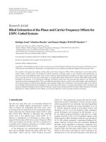
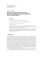
5.1. Pure Channel Estimation Error. In Figure 4, we show
the average BER at the destination for three schemes:
direct transmission without using relay nodes, traditional
decode-and-forward cooperative transmission using MRC
combining, and the proposed scheme. Recall that the
traditional MRC does not consider the possible decoding
errors at the relay. The relay moves from location (50, 100)
to (1000, 100). Compared with the direct transmission (i.e.,
no relay), the two cooperative transmission schemes can
achieve better performance with a wide range of locations.
We also see that the performance of MRC cooperative
transmission degrades when the relay is very close to the
destination because the source to relay channel is not good
and channel estimation errors can occur at the relay. The
MRC scheme has a minimum at around 180–190. The
proposed scheme considers the relay’s error in the receiver
and therefore yields better performance than the traditional
MRC.
10 EURASIP Journal on Wireless Communications and Networking
Performance versus location
0 200 400 600 800 1000
Horizontal location (m) of the relay node
10
−4
10
−3
10
−2
10
−1
10
0
Average BER at the destination
No cooperation
MRC
Proposed combining at the waveform level
Figure 4: Comparison among the proposed schemes, cooperative
transmission using MRC, and direction transmission.
m
r
over time
0 20 40 60 80 100 120 140
Time
0
0.1
0.2
0.3
0.4
0.5
0.6
0.7
0.8
0.9
1
m
r
trust value
Malicious relay
Selfish/leaving relay
Honest node
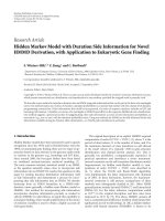
Figure 5: Trust value (i.e., m
i
value) over time with estimation error
and untrustworthy relays (attacks at time 10 and time 50).
5.2. Selfish Node and Malicious Node. In this set of sim-
ulations, there are 4 relays. The link quality (mean value
α/(α + β)) is shown in Figure 5 and the average SNR at the
destination is shown in Figure 6. At time 10, one relay starts
to send the opposite bits (i.e., sending 1 (or 0) if receiving 0
(or 1)). This could be due to severe channel estimation error
or maliciousness. Obviously the destination’s performance
drops significantly. According to Algorithm 1, the m
i
value
of this malfunctioning or malicious relay is reduced. Within
Performance over time
0 20 40 60 80 100 120 140
Time
0
2
4
6
8
10
12
14
16
Average SNR
No cooperation
Cooperation under attacks and recovery
Figure 6: Average SNR over time with estimation error, malicious
and selfish behavior (attacks at time 10 and time 50).
5 time slots, the destination recognizes the misbehaving relay
because its m
i
value has been reduced for a certain number
of times continually. Then, the destination reduces its weight
to zero. As a result, the messages from the misbehaving
relay will not be used in the signal combination process.
The other relays’ m
i
values, which might be affected by the
misbehaving relay, will recover gradually after more packets
are transmitted correctly. At time 50, another node leaves the
network due to mobility or simply stops forwarding anything
(i.e., selfish behavior). It takes about 45 time slots for the
destination to remove this relay.
Several important observations are made.
(1) When there are malicious relays, the SNR at the
destination drops significantly. In this case, the
performance of traditional cooperative transmission
is even worse than that of direct transmission. This
can be seen by comparing the dashed line and solid
line around time 10 in Figure 6.
(2) When the proposed scheme is used, the m
i
value
maintained by the destination can capture the
dynamics in the relay nodes. As shown in Figure 5,
the m
i
value of the malicious node rapidly drops
to zero, and the m
i
value of the selfish node drops
quickly too. The m
i
values of honest nodes will be
affected at the beginning of the attack, but can recover
even if the attack is still going on.
(3) The trust-assisted cooperative transmission scheme
results in higher SNR at the destination, com-
pared with the noncooperative (direct) transmission
scheme, except during a very short time at the
beginning of the attacks.
We can see that the cooperative transmission in its original
design is highly vulnerable to attacks from malicious relays.The
EURASIP Journal on Wireless Communications and Networking 11
Outage versus jamming power
0.02 0.04 0.06 0.08 0.10.12 0.14 0.16 0.18 0.2
Jamming power
0
0.1
0.2
0.3
0.4
0.5
0.6
0.7
0.8
0.9
1
Outage probability
No jamming attack
Jamming, direct transmission
Proposed scheme with 2 relays
Proposed scheme with 10 relays
Figure 7: Outage probability versus jamming power.
proposed scheme can greatly reduce the damage of malicious
attacks, and partially maintain the performance advantage of
cooperative transmission.
5.3. Jamming Attack. The usage of relay nodes provides
opportunities to the attackers. This is a disadvantage of
cooperative transmission from the security point of view. On
the other hand, we discover that cooperative transmission (if
used properly) can benefit security in wireless networks.
Intuitively, wireless networks are subject to physical layer
Denial of Service (DoS) attacks, such as jamming. Relay
nodes provide spatial diversity in wireless transmission. A
message (or waveform) arrives at the destination through
multiple physical channels and paths. As a result, the desti-
nation may have a better chance to receive the source node’s
message in cooperative transmission than in traditional
transmission, when some channels are jammed. Therefore,
we study the performance of the proposed cooperative
transmission scheme against wireless jamming attacks.
One jammer is randomly located within the square. An
outage is reported if the SNR at the destination is lower than
a threshold of 0 dB, under which the link is not reliable.
Figure 7 shows the outage probability versus jamming power.
When using the proposed cooperative transmission scheme,
the outage probability is reduced compared with the direct
transmission case. In the example of 10 relays, when the
jamming power is 200 mW, which is twice the source
transmission power, more than 10% of packets are still
correctly received at the destination. Even with 2 relays, there
is an obvious reduction in the outage probability.
Figure 8 shows that the outage probability decreases as
the number of relays increases. For example, to achieve
50% outage with jamming power 100 mW, 20 relay nodes
Outage versus number of nodes
0 5 10 15 20 25 30 35
Number of nodes
0.2
0.3
0.4
0.5
0.6
0.7
0.8
0.9
1
Outage
Jamming power 50mW
Jamming power 100mW
Jamming power 200mW
Figure 8: Outage probability versus the number of relays in the
proposed scheme.
Outage probability versus jammer location
100 200 300 400 500 600
700 800 900
Jammer horizontal location
0
0.1
0.2
0.3
0.4
0.5
0.6
0.7
0.8
0.9
1
Outage probability
No jamming attack
Jamming, direct transmission
Proposed scheme with 2 relays
Proposed scheme with 10 relays
Figure 9: Outage probability versus jammer’s location.
are needed. We can see that cooperative transmission can
effectively reduce the outage probability, when the jamming
power is comparable to the regular transmission power.
In Figure 9, the jammer moves from (100, 0) to (900,0)
with power 100 mW. We see that the location of the jammer
plays a vital role in the attack. If the jammer is far away
from the destination, the proposed scheme can significantly
reduce the effect of jamming. For example, with 10 relays and
jammer location at (900,0), the performance is almost the
12 EURASIP Journal on Wireless Communications and Networking
Attack for false correlation announcement
0 5 10 15 20 25 30
Time
10
−1
Average BER
No cooperation
MRC
Without attack
Under attack
Figure 10: Bad-mouthing attack and self-healing.
same as that of no jammer case. However, if the jammer is
very close to the destination, the proposed scheme can only
improve the performance slightly.
In both Figures, we see that the proposed cooperative
transmission scheme can reduce link outage probability. This
is the advantage of cooperative transmission from the security
point of view.
5.4. Bad-Mouthing Attack. In this simulation, one relay is
located at (1000,100). Since the relay is far from the source,
the source-relay link quality is bad. The relay sends honest
link quality reports at the beginning. Then at time 10,
the relay launches the bad-mouthing attack by telling the
destination that its link to the source is perfect. As a result,
the destination gives higher weight to the signal forwarded
by the relay. Since the relay’s signal is not perfect, the BER
performance at the destination degrades a lot, even lower
than that in the direct transmission. Using the detection
method in Section 4.4, the destination realizes that it is under
attack and suspects the relay’s link quality report at time 11.
Then the destination reduces the m
i
value of the relay until
the analytical BER agrees with the observed BER.
Figure 10 shows the average BER of four schemes: direct
transmission, the proposed scheme without attack, the
proposed scheme under the bad-mouthing attack, and the
traditional MRC scheme. Three observations are made. First,
without the bad-mouthing attack, the proposed scheme
yields a much lower BER than the direct transmission.
Second, at the beginning of the bad-mouthing attack, the
proposed scheme can have worse performance than the
direct transmission. Third, the proposed scheme can recover
from the bad-mouthing attack after a period of time.
6. Conclusions
In this paper, we investigate the security issues related to
cooperative transmission from three angles: (1) vulnerabili-
ties analysis of traditional cooperative transmission schemes;
(2) design of the trust-assisted cooperative transmission
scheme that is robust against attacks; and (3) illustration of
the potential advantage of physical layer cooperation against
wireless jamming attacks.
In particular, it is demonstrated that the security vulner-
abilities of traditional cooperative transmission significantly
damage the performance. The proposed trust-assisted coop-
erative transmission scheme can handle relays’ misbehavior
as well as channel estimation errors. The core idea of
this scheme has four parts. First, the wireless link quality
is described by trust values in the format of the beta
function. This solves the problem that traditional SNR-
based and BER-based channel information cannot accurately
describe channel quality under attacks. Second, based on
the properties of the beta function, we develop a method
to calculate the link quality over multiple hops. Third, the
trust-based link quality information is used to perform
signal combination at the destination. Fourth, the bad-
mouthing attack is detected by comparison between theo-
retical BER and observed BER. The proposed scheme can
be implemented in a fully distributed manner and has low
implementation overhead. Compared with the traditional
cooperative transmission schemes, which are vulnerable to
attacks, the proposed scheme can maintain the performance
advantage over the direct transmission under various attacks.
Additionally, compared with the direct transmission, the
proposed scheme can reduce the damage caused by wireless
jamming attacks, when the jamming power is comparable
to the regular transmission power. This is the advantage of
physical layer cooperation from the security point of view.
Acknowledgments
Some ideas and results in this manuscript appear in an earlier
conference paper published in IEEE Globecom 2007. This
work is supported by NSF CNS-0910461, NSF CNS-0905556,
and NSF CNS-0831315.
References
[1] A. Sendonaris, E. Erkip, and B. Aazhang, “User cooperation
diversity-part I: system description,” IEEE Transactions on
Communications, vol. 51, no. 11, pp. 1927–1938, 2003.
[2] J.N.Laneman,D.N.C.Tse,andG.W.Wornell,“Cooperative
diversity in wireless networks: efficient protocols and outage
behavior,” IEEE Transactions on Information Theory, vol. 50,
no. 12, pp. 3062–3080, 2004.
[3] />[4] J. Luo, R. S. Blum, L. J. Greenstein, L. J. Cimini, and A. M.
Haimovich, “New approaches for cooperative use of multiple
antennas in ad hoc wireless networks,” in Proceedings of the
60th IEEE Vehicular Technology Conference (VTC ’04), vol. 4,
pp. 2769–2773, Los Angeles, Calif, USA, September 2004.
[5] A. Bletsas, A. Lippman, and D. P. Reed, “A simple distributed
method for relay selection in cooperative diversity wireless
networks, based on reciprocity and channel measurements,”
in of the 61st IEEE Vehicular Technology Conference (VTC ’05),
vol. 3, pp. 1484–1488, Stockholm, Sweden, May 2005.
EURASIP Journal on Wireless Communications and Networking 13
[6] Z. Han, T. Himsoon, W. Siriwongpairat, and K. J. R.
Liu, “Resource allocation for multiuser cooperative OFDM
networks: who helps whom and how to cooperate,” IEEE
Transactions on Vehicular Transactions, vol. 58, no. 6, pp. 2378–
2391, 2009.
[7]B.Wang,Z.Han,andK.J.R.Liu,“Stackelberggamefor
distributed resource allocation over multiuser cooperative
communication networks,” in Proceedings of the IEEE Global
Telecommunications Conference (GLOBECOM ’06), pp. 1–5,
San Francisco, Calif, USA, November-December 2006.
[8] A. Jøsang, R. Ismail, and C. Boyd, “A survey of trust and
reputation systems for online service provision,” Dec ision
Support Systems, vol. 43, no. 2, pp. 618–644, 2007.
[9] A. Jøsang and R. Ismail, “The beta reputation system,” in
Proceedings of the 15th Bled Electronic Commerce Conference,
Bled, Slovenia, June 2002.
[10] Z. Han and H. V. Poor, “Lifetime improvement in wireless sen-
sor networks via collaborative beamforming and cooperative
transmission,” IET Microwaves, Antennas & Propagation, vol.
1, no. 6, pp. 1103–1110, 2007.
[11] Z. Han and H. V. Poor, “Coalition games with cooperative
transmission: a cure for the curse of boundary nodes in selfish
packet-forwarding wireless networks,” IEEE Transactions on
Communications, vol. 57, no. 1, pp. 203–213, 2009.
[12] Y. Zhao, R. S. Adve, and T. J. Lim, “Improving amplify-
and-forward relay networks: optimal power allocation versus
selection,” in Proceedings of the IEEE International Symposium
on Information Theory (ISIT ’06), pp. 1234–1238, Seattle,
Wash, USA, July 2006.
[13] Y. Zigui, J. Liu, and A. Host-Madsen, “Cooperative routing
and power allocation in ad-hoc networks,” in Proceedings of
the IEEE Global Telecommunicat ions Conference (GLOBECOM
’05), vol. 5, pp. 2730–2734, Dallas, Tex, USA, December 2005.
[14] C. K. Lo, R. W. Heath Jr., and S. Vishwanath, “Hybrid-ARQ
in multihop networks with opportunistic relay selection,” in
Proceedings of the IEEE International Conference on Acoustics,
Speech and Sig nal Processing (ICASSP ’07), vol. 3, pp. 617–620,
Honolulu, Hawaii, USA, April 2007.
[15] W. Saad, Z. Han, M. Debbah, and A. Hjørungnes, “Coalition
formation for distributed-user cooperation in wireless net-
works,” in Proceedings of the IEEE Wireless Communications
and Networking Conference (WCNC ’08),LasVegas,Nev,USA,
April 2008.
[16] W. Stallings, Protect Your Privacy: A Guide for PGP Users,
Prentice-Hall, Englewood Cliffs, NJ, USA, 1995.
[17] S. D. Kamvar, M. T. Schlosser, and H. Garcia-Molina, “The
eigentrust algorithm for reputation management in P2P
networks,” in Proceedings of the 12th International Conference
on World Wide Web, pp. 640–651, Budapest, Hungary, May
2003.
[18] S. Ganeriwal and M. B. Srivastava, “Reputation-based frame-
work for high integrity sensor networks,” in Proceedings of the
ACM Workshop on Security of Ad Hoc and Sensor Networks
(SASN ’04), pp. 66–77, Washington, DC, USA, October 2004.
[19] M. Langheinrich, “When trust does not compute—the role of
trust in ubiquitous computing,” in Proceedings of the 5th Inter-
national Conference on Ubiquitous Computing (UBICOMP
’03), Seattle, Wash, USA, October 2003.
[20] Y. L. Sun, W. Yu, Z. Han, and K. J. R. Liu, “Information the-
oretic framework of trust modeling and evaluation for ad hoc
networks,” IEEE Journal on Selected Areas in Communications,
vol. 24, no. 2, pp. 305–317, 2006.
[21] P. L. Yu, J. S. Baras, and B. M. Sadler, “Physical-layer
authentication,” IEEE Transactions on Information Forensics
and Security, vol. 3, no. 1, pp. 38–51, 2008.
[22] L. Xiao, L. J. Greenstein, N. B. Mandayam, and W. Trappe,
“Using the physical layer for wireless authentication in time-
variant channels,” IEEE Transactions on Wireless Communica-
tions, vol. 7, no. 7, pp. 2571–2579, 2008.
[23] G. Theodorakopoulos and J. S. Baras, “Trust evaluation in ad-
hoc networks,” in
Proceedings of the 3rd ACM Workshop on
Wireless Security (WiSE ’04), pp. 1–10, Philadelphia, Pa, USA,
October 2004.
[24] J. G. Proakis, Digital Communications, McGraw-Hill, New
York, NY, USA, 3rd edition, 1995.
[25] S. Boyd and L. Vandenberghe, Convex Optimization,Cam-
bridge University Press, Cambridge, UK, 2006.
[26] Z. Han and K. J. R. Liu, Resource Allocation for Wireless
Networks: Basics, Techniques, and Applications, Cambridge
University Press, Cambridge, UK, 2008.
[27] A. K. Sadek, W. Su, and K. J. R. Liu, “A class of cooperative
communication protocols for multi-node wireless networks,”
in Proceedings of the 6th IEEE Workshop on Signal Processing
Advances in Wireless Communications (SPAWC ’05), pp. 560–
564, New York, NY,USA, June 2005.
[28] J. Boyer, D. D. Falconer, and H. Yanikomeroglu, “Multihop
diversity in wireless relaying channels,” IEEE Transactions on
Communications, vol. 52, no. 10, pp. 1820–1830, 2004.
[29] Y. L. Sun, Z. Han, W. Yu, and K. J. R. Liu, “A trust
evaluation framework in distributed networks: vulnerability
analysis and defense against attacks,” in Proceedings of the 25th
IEEE International Conference on Computer Communications
(INFOCOM ’06), pp. 1–13, Barcelona, Spain, April 2006.