Báo cáo hóa học: " Research Article Construction and Iterative Decoding of LDPC Codes Over Rings for Phase-Noisy Channels ppt
Bạn đang xem bản rút gọn của tài liệu. Xem và tải ngay bản đầy đủ của tài liệu tại đây (768.02 KB, 9 trang )
Hindawi Publishing Corporation
EURASIP Journal on Wireless Communications and Networking
Volume 2008, Article ID 385421, 9 pages
doi:10.1155/2008/385421
Research Article
Construction and Iterative Decoding of LDPC Codes Over
Rings for Phase-Noisy Channels
Sridhar Karuppasami and William G. Cowley
Institute for Telecommunications Research, University of South Australia, Mawson Lakes, SA 5095, Australia
Correspondence should be addressed to Sridhar Karuppasami,
Received 1 November 2007; Revised 7 March 2008; Accepted 27 March 2008
Recommended by Branka Vucetic
This paper presents the construction and iterative decoding of low-density parity-check (LDPC) codes for channels affected by
phase noise. The LDPC code is based on integer rings and designed to converge under phase-noisy channels. We assume that
phase variations are small over short blocks of adjacent symbols. A part of the constructed code is inherently built with this
knowledge and hence able to withstand a phase rotation of 2π/M radians, where “M” is the number of phase symmetries in
the signal set, that occur at different observation intervals. Another part of the code estimates the phase ambiguity present in
every observation interval. The code makes use of simple blind or turbo phase estimators to provide phase estimates over every
observation interval. We propose an iterative decoding schedule to apply the sum-product algorithm (SPA) on the factor graph of
the code for its convergence. To illustrate the new method, we present the performance results of an LDPC code constructed over
Z
4
with quadrature phase shift keying (QPSK) modulated signals transmitted over a static channel, but affected by phase noise,
which is modeled by the Wiener (random-walk) process. The results show that the code can withstand phase noise of 2
◦
standard
deviation per symbol with small loss.
Copyright © 2008 S. Karuppasami and W. G. Cowley. This is an open access article distributed under the Creative Commons
Attribution License, which permits unrestricted use, distribution, and reproduction in any medium, provided the original work is
properly cited.
1. INTRODUCTION
In the past decade, plenty of work was done in the con-
struction and decoding of LDPC codes [1]. In general, the
code construction techniques were motivated to provide a
reduced encoding complexity and better bit-error rate (BER)
performance. The channels considered are generally either
additive white Gaussian (AWGN) or binary erasure channels.
However, many real systems are affected by phase noise
(e.g., DVB-S2). The severity of the phase noise depends
on the quality of the local oscillators and the symbol rate.
Hence the performance of codes on the channels with phase
disturbances are of practical significance.
Over the past few years, iterative decoding for channels
with phase disturbance has received lots of attention [2–
7]. In [2, 3], the authors have proposed algorithms to
apply over a factor graph model that involves the phase
noise process. They used canonical distributions to deal
with the continuous phase probability density functions. In
particular, their approach based on Tikhonov distribution
yields a good performance. In [4], the authors developed
algorithms for noncoherent decoding of turbo-like codes for
the phase-noisy channels. These schemes make use of pilot
symbols for either estimation or decoding. In [5], the authors
showed the rotational robustness of certain codes under a
constant phase offset channel with the presence of cycle slips
only during the initial part of the codeword.
In [6], the authors used smaller observation intervals
to tackle varying frequency offset in the context of serially
concatenated convolutional codes (SCCCs). They used blind
and turbo phase estimators to provide a phase estimate for
every sub-block. Since the phase estimates obtained from
the blind phase estimator (BPE) are phase ambiguous, each
sub-block is affected by an ambiguity of
2π/M
radians.
By differentially encoding the sub-blocks independently, the
authors tackled the phase ambiguity. However, using an
inner differential encoder along with an LDPC code provides
a loss in performance and the degree distributions of the
LDPC code needs to be optimized [7].
The concept of smaller observation intervals in the
presence of phase disturbances is attractive and offers low
complexity as well. Intuitively, as the observation interval get
2 EURASIP Journal on Wireless Communications and Networking
smaller more phase variation may be tackled. On the other
hand,phaseestimatorsproducepoorestimateswithsmaller
observation intervals. However, if the phase estimation error
is smaller than
π/M,
the decoder may be able to converge
correctly.
In our earlier work [8], we used sub-blocks in a binary
LDPC-coded receiver to tackle residual frequency offset. The
received symbol vector was split into many sub-blocks and
BPE was used to provide a phase estimate across every sub-
block. We introduced the concept of “local check nodes”
(LCNs) to resolve the phase ambiguity created by the BPE
on the sub-blocks. Local check nodes are odd degree check
nodes connected to the variable nodes present within a
single sub-block. In (1), the local check nodes correspond
to the top four rows of the parity-check matrix, in which
the bottom (dotted) part is connected according to random
construction. In this small example, the LCN degree (d
L
c
)is
three and if the sub-block size (N
b
) is six symbols, the parity
check matrix provides N
b
/d
L
c
= 2LCNstoresolvethephase
ambiguity in each sub-block
H
=
⎡
⎢
⎢
⎢
⎢
⎢
⎢
⎢
⎢
⎢
⎢
⎢
⎢
⎢
⎣
111000000000
000111000000
000000111000
000000000111
.
.
.
.
.
.
.
.
.
.
.
.
.
.
.
.
.
.
.
.
.
.
.
.
.
.
.
.
.
.
⎤
⎥
⎥
⎥
⎥
⎥
⎥
⎥
⎥
⎥
⎥
⎥
⎥
⎥
⎦
. (1)
The phase-ambiguity-resolved vector is decoded by an LDPC
decoder. Turbo phase/frequency estimates (e.g., [9]) are
obtained during iterations to facilitate the convergence.
The quality of the phase ambiguity estimate is better with
more LCNs. Hence with reduced sub-block sizes, the phase
ambiguity estimate is less reliable and the code suffers
performance degradation.
Following [6, 8], but with a different perspective, we
addressed the problem of phase noise for BPSK signals in the
presence of a binary LDPC-coded system [10]. In particular,
we incorporated the observation that, even under large phase
disturbances the variation in phase over adjacent symbols
are normally small. We created a set of check nodes called
“global check nodes” (GCNs) that converge irrespective of
phase rotations (0 or π radians) in any sub-blocks. We
used BPE or TPE to provide a phase estimate in each sub-
block. After the convergence of GCN, we used only one
LCNpersub-blocktoresolvethephaseambiguitypresent
in the sub-block. We found that even under relatively large
phase noise and observation intervals, the method provided a
good performance for BPSK signals. We did not make use of
pilot symbols and the complexity is low. However, we found
that the extension of the above approach to higher-order
modulations was very difficult with a binary LDPC code.
In particular, with a binary LDPC code, constructing global
check nodes that converge irrespective of a phase rotation
(a multiple of 2π/M radians) in the sub-blocks was difficult.
This paper addresses the problem of extending the above
code construction technique to higher-order signal constella-
tions based on integer rings. Specifically, we construct LDPC
codes over rings with certain constraints on the placement of
edges and edge gains such that they, along with sub-block
phase estimation techniques, provide good performance
under phase-noisy channels with low complexity. Under a
noiseless channel, we present edge constraints based on inte-
ger rings generalized for any phase-symmetric modulation
scheme, under which the convergence of the global check
nodes is guaranteed in the presence of phase ambiguities
in any sub-block. Similarly, we present generalized edge
constraints for the local check node such that they are
able to resolve the phase ambiguity in the sub-block. To
illustrate the concepts discussed in this paper under a phase-
noisy channel, we show the performance of an LDPC code
constructed over
Z
4
with codewords mapped onto QPSK
modulation, where the transmitted symbol s
k
∈{s
m
k
=
e
j((π/2)m+π/4)
}, m ={0,1, 2, 3}.
The remainder of the paper is organized as follows. In
Section 2, we discuss the channel model considered for our
simulations. In Section 3, we address the effects of phase
ambiguity on the check nodes and discuss the construction
of global and local check nodes. In Section 4,weexplain
code construction and present a matrix inversion technique
to obtain the generator matrix. In Section 5,weexplain
the receiver architecture and detail the iterative decoding
for the convergence of these codes. We also show the
additional computational complexity required due to the
phase estimation process. In Section 6, we discuss the BER
performance of the proposed receiver under phase noise
conditions using the code constructed over
Z
4
for QPSK
signal set. In Section 7, we discuss the benefits of the blind
phase estimator in reducing the computational complexity
involved with the turbo phase estimation and also show the
BER performance of the low-complexity iterative receiver
with the
Z
4
code under phase noise conditions. We conclude
in Section 8 by summarizing the results of this paper.
2. CHANNEL MODEL
An information sequence is encoded by an (N, K) nonbinary
LDPC code constructed over integer rings (
Z
M
), where N
and K represent the length and dimension of the code and
Z
M
denote the integers {0,1, 2, , M − 1} under addition
modulo M, respectively. The alphabets over
Z
M
are mapped
onto complex symbols s using phase shift keying (PSK)
modulation with M phase symmetries. The complex symbols
are transmitted over a channel affected by carrier phase
disturbance and complex additive white Gaussian noise.
Ideal timing and frame synchronization are assumed
and henceforth, all the simulations assume one sample per
symbol. At the receiver, after matched filtering and ideal
sampling, we have
r
k
= s
k
e
jθ
k
+ n
k
, k = 0, 1, ,N
s
−1, (2)
where s
k
, r
k
, θ
k
,andn
k
are the kth component of the vectors
r, s, θ,andn,oflengthN
s
, respectively. The noise samples
n
k
contain uncorrelated real and imaginary parts with zero
mean and two-sided power spectral density (PSD) of N
0
/2.
S. Karuppasami and W. G. Cowley 3
The phase noise process θ
k
is generated using the Wiener
(random-walk) model described by
θ
k
= θ
k−1
+ Δ
k
, k = 1, 2, , N
s
−1, (3)
where Δ
k
is a white real Gaussian process with a standard
deviation of σ
Δ
. θ
0
is generated uniformly from the distribu-
tion (
−π, π).
Let us divide the received symbol vector r of length
N
s
into B sub-blocks of length N
b
. Assuming small phase
variations over adjacent symbols, we may approximate the
phase variations on the symbol in the lth sub-block by a
mean phase offset
θ
l
∈ (−π, π). Similar to (2), the received
sequence can be expressed as
r
k
s
k
e
j
θ
l
+ n
k
, l = 0, 1, , B −1, (4)
where k
= N
b
l + k, k = 0, 1, , N
b
− 1. While the
channel model in (2) is used in our simulations, we use
the approximate model in (4) for the code construction
and receiver-side processing. The approximate phase offset
over lth sub-block,
θ
l
∈ (−π, π) can be represented as the
summation of an ambiguous phase offset φ
l
∈ (−π/M, π/M)
and the phase ambiguity α
l
∈{0,2π/M,4π/M, ,2(M −
1)π/M}.
The proposed receiver tackles modest to high levels of
phase noise. For instance, the phase noise considered in this
paper (Wiener model with σ
Δ
of 1
◦
and 2
◦
)isseveraltimes
larger than the phase noise mentioned in the European Space
Agency model (Wiener model with σ
Δ
= 0.3
◦
per symbol
[2]).However,duetotheassumptionsmadein(4), the
proposed receiver will not be able to tackle large amounts
of phase noise, such as the Wiener model with σ
Δ
= 6
◦
per
symbol in [2, 3].
3. EFFECT OF PHASE AMBIGUITIES ON
THE CHECK NODES
In this section, we address the effect of phase rotations that
are multiples of
2π/M
radians on the global and local check
nodes of an LDPC code constructed over
Z
M
.LetH
i,j
be the
elements of the parity check matrix participating in the ith
check node such that,
d
c
j=1
H
i,j
x
j
= 0(modM), (5)
where d
c
is the degree of the check node, x
j
is the jth symbol
participating in the ith check node and the value of H
i,j
is
chosen from the nonzero elements of
Z
M
. In the remaining
subsections, we denote the degree of the GCN and LCN as
d
G
c
and d
L
c
,respectively.
3.1. Global check nodes
Unlike local check nodes, the edges of the GCN are spread
across many sub-blocks. Let p be the number of global check
node edges connected to symbols present within one sub-
block. Say, all symbols in that sub-block are rotated by 2πt/M
radians, where t
∈{0, 1, , M − 1}. As a result, the check
equation in (5)becomes
p
j=1
H
i,j
x
j
+ t
+
d
G
c
j=p+1
H
i,j
x
j
=
p
j=1
H
i,j
t +
d
G
c
j=1
H
i,j
x
j
= t
p
j=1
H
i,j.
(6)
Thus for arbitrary integer t,(6) becomes zero only if
p
j=1
H
i,j
= 0(modM). (7)
In the case of binary LDPC code, p should be even in
ordertosatisfy(7). For LDPC codes over higher-order rings,
p can either be odd or even depending on the values of H
i,j
.
In this work, we select the values of H
i,j
from the set of
nonzero divisors of
Z
M
({1, 3} from Z
4
)toavoidproblems
during matrix inversion. As a result, p becomes even in the
case of LDPC code over integer rings which further makes d
G
c
as well, even.
Example 1. Assume an LDPC code constructed over
Z
4
with
B
= 4 sub-blocks. Consider a degree-8 GCN whose edges
are connected to two symbols per sub-block (p
= 2) and the
corresponding edge gains be g
= [1,3,1,3,3,1,1,3].Oneset
of symbols that satisfies this check is x
= [3,2,3,1,1,3,0,1].
Let us assume that sub-block one and four are rotated by π/2
and π radians, respectively. Therefore, the sub-block rotated
version of x,sayx
r
= [0,3,3,1,1,3,2,3].Itcanbeseenthat
x
r
still satisfies the parity check equation with the same g.
Note that each sub-block has one edge with value “1” and
another with “3,” whose sum is 0 (mod 4) as required by (7).
3.2. Local check nodes
Local check nodes resolve the phase ambiguity present in a
sub-block. Let the elements H
i,j
participating in check i be
selected from a single sub-block such that,
d
L
c
j=1
H
i,j
/
=0(mod2). (8)
Alternatively, (8) represents that the element
d
L
c
j=1
H
i,j
is
chosen from the set of nonzero divisors from
Z
M
,which
is achieved by performing the summation over modulo 2
rather than M.IfmoduloM is used, the check node will not
resolve certain phase ambiguities as explained below.
If all the symbols x
j
participating in ith local check node
are rotated by 2πt/M radians, then using (5)and(8), we can
show that for every t there exists a distinct residue (mod M)
which provides a solution for the phase ambiguity present on
the participating symbols x
j
. Considering all the operations
below are modulo M,
d
L
c
j=1
H
i,j
x
j
+ t
=
d
L
c
j=1
H
i,j
x
j
+
d
L
c
j=1
H
i,j
t = t
d
L
c
j=1
H
i,j
.
(9)
4 EURASIP Journal on Wireless Communications and Networking
Hence t can be written as
t
=
d
L
c
j=1
H
i,j
x
j
+ t
×
d
L
c
j=1
H
i,j
−1
(mod M). (10)
In case where the
d
L
c
j=1
H
i,j
do not have a multiplicative
inverse in
Z
M
(say
d
L
c
j=1
H
i,j
equals a zero divisor), then (9)
is satisfied for any t
∈{zero divisors in Z
M
} and hence
the phase ambiguity estimate is not unique. Thus choosing
d
L
c
j=1
H
i,j
with a multiplicative inverse in Z
M
ensures phase
ambiguity resolution. Further, by selecting the edge gains of
the LCN from the nonzero divisors of
Z
M
,whichareodd
integers less than M, we require an odd number of edges to
satisfy (8). Hence the degree of the local check node d
L
c
is
always considered to be odd in this work.
Example 2. Let us consider the code and rotations as in
Example 1. Let the code include a degree-3 LCN whose edges
with gains [1, 3, 1] are connected to the first sub-block. A set
of symbols that satisfies this check is x
= [3,0,1].Duetothe
rotation of π/2 radians in the first sub-block, x
r
= [0,1,2].
Using (10), we can evaluate that t
= 1 which corresponds to
π/2 radians.
4. NONBINARY CODE CONSTRUCTION
We apply the above set of principles in constructing codes
that are beneficial in dealing with phase noise channels.
Similar to [11], we construct a binary code and choose the
nonzero divisors from
Z
M
as edge gains such that check
conditions as described in Section 3 are satisfied.
4.1. Code construction
Following Section 2,letussaywehave“B” sub-blocks of
length N
b
. A binary parity check matrix H
N−K×N
is con-
structed such that it involves two parts:
H
=
⎡
⎢
⎢
⎣
H
resolving
············
H
converging
⎤
⎥
⎥
⎦
. (11)
The upper (B
× N) part of the matrix, called H
resolving
,
involves B local check nodes in contrast to N
b
/d
c
LCNs as
in our previous method [8], which are used to resolve the
phase ambiguity in B sub-blocks. The lower (N
−K −B×N)
part of the matrix, called H
converging
, contains N − K − B
check nodes whose neighbours are selected such that their
convergence is independent of the phase ambiguities in the
sub-block. We assume the degree of all the local (global)
check nodes to be equal to d
L
c
(d
G
c
). The codes are designed
to be check biregular, (i.e., with two different degrees, d
L
c
and
d
G
c
). However, there is no constraint on the variable node
degree.
We construct the code as per the following procedure.
(1) Construction of local check nodes: the edges of the local
check node are connected to the first d
L
c
symbols of the
sub-block for which it resolves the phase ambiguity.
For example, assuming d
L
c
= 3, let H
ij
= 1where
j corresponds to the first 3 columns of each sub-
block. However, we can arbitrarily choose the set of d
L
c
symbols from any part of the sub-block.
(2) Construction of global check nodes: for every symbol,
the parity checks in which the symbol participates
are randomly chosen based on its degree and (7). As
in Example 1, every global check node participates in
only two symbols from a sub-block. Care was taken to
avoid short cycles after constructing every column.
To illustrate the local and global check nodes, a small
parity check matrix (H) is shown in (12). The first four rows
corresponding to the local check nodes (H
resolving
) are shown
at the top. The two rows below the local check nodes are
connected globally and also have p
= 2 edges connected
to symbols from a sub-block. The restriction of two edges
per sub-block provides a better connectivity in the code.
The same technique is continued to construct the remaining
global check nodes in the dotted part of the matrix. The local
and the global check nodes shown in the first and fifth rows
of the H-matrix are used in the previous examples. A portion
of the Tanner graph of the H matrix, in (12), is shown in
Figure 1. Local check nodes (shaded checks) and their edges
(solid lines) are distinguished from the global check nodes
and their edges (dash-dotted lines)
H
=
⎡
⎢
⎢
⎢
⎢
⎢
⎢
⎢
⎢
⎢
⎢
⎢
⎢
⎢
⎢
⎢
⎢
⎢
⎢
⎢
⎢
⎢
⎢
⎢
⎢
⎢
⎣
131000000000000000000000
000000111000000000000000
000000000000333000000000
000000000000000000313000
····································
100300010300030100001030
010300031000003100130000
.
.
.
.
.
.
.
.
.
.
.
.
.
.
.
.
.
.
.
.
.
.
.
.
.
.
.
.
.
.
.
.
.
.
.
.
.
.
.
.
.
.
.
.
.
.
.
.
.
.
.
.
.
.
.
.
.
.
.
.
.
.
.
.
.
.
⎤
⎥
⎥
⎥
⎥
⎥
⎥
⎥
⎥
⎥
⎥
⎥
⎥
⎥
⎥
⎥
⎥
⎥
⎥
⎥
⎥
⎥
⎥
⎥
⎥
⎥
⎦
.
(12)
4.2. Some comments on encoding
We used the Gaussian elimination (GE) approach to obtain
a systematic generator matrix. Even though the edge gains of
the parity check matrix are nonzero divisors, we encountered
zero divisors (
{2} in the case of Z
4
) during GE in the
diagonal part of the matrix. To avoid this problem, we
interchanged columns across the parity check matrix such
that we obtain a generator matrix (G) corresponding to
the column-interchanged parity check matrix (H
). Since
we wanted to use the original H matrix instead of H
,
we created a permutation table (P) to record the columns
S. Karuppasami and W. G. Cowley 5
p = 2
B
= 4
LCN (d
L
c
= 3)
GCN (d
G
c
= 8)
.
.
.
Figure 1: Tanner graph of the H matrix in (12), illustrating local
and global check nodes.
that are interchanged during inversion. Alternate inversion
techniques may avoid the use of permutation table P.
A summary of the communication system used in the
simulations is given in Figure 2. The message is encoded by
the generator matrix G to produce the codeword (c). The
codeword c undergoes inverse permutation to produce c
.
The codeword is transmitted through the composite channel.
Since the permuted-encoded symbols are the codewords of
the original code H, the decoder decodes the codeword. The
decoded codeword
c
is again permuted to give the original
codeword
c.
5. RECEIVER ARCHITECTURE AND ITERATIVE
DECODING SCHEDULE
The receiver architecture to tackle large phase disturbances
is shown below in Figure 3. We used the SPA algorithm
for LDPC codes over rings, similar to [12]. In the case of
an AWGN channel, the SPA may be applied over the
entire code for convergence. However, in the presence of
phase disturbances, phase estimators provide an ambiguous
phase estimate and hence the SPA is applied only over the
rotationally invariant part of the factor graph, that is, the
graph involving global check nodes only.
This section discusses the application of SPA on the factor
graph of the code with phase offset on every sub-block such
that the benefits of local and global check nodes are achieved.
Thus we split up the decoding into three phases as described
below.
(1) Converging phase.
(a) The likelihood vector, of length M, for the kth
variable node is initialized with the channel like-
lihoods, p(r
k
| s
k
= s
m
k
) = (1/2πσ
2
)exp{−(|r
k
−
s
m
k
|
2
)/2σ
2
},wherem ={0, 1, , M − 1}, k =
{
0, 1, , N
s
−1} and σ
2
is the noise variance.
(b) The SPA is applied over the H
converging
part of the
code alone. Local check nodes are not used. The
messages coming from these nodes are assigned
to be equiprobable.
(c) After every d iterations, the turbo phase estima-
tor (TPE) [9] estimates the phase offset
φ
l
,which
is given by
φ
l
= arg
k
r
k
a
∗
k
, (13)
where k
,asdefinedin(4), is the kth component
in the lth sub-block and a
∗
k
is the complex
conjugate of the soft symbol estimate. The soft
symbol estimate a
k
of the symbol s
k
is given by
a
k
=
M−1
m=0
s
m
k
p
s
k
= s
m
k
| r
k
, (14)
where p(s
k
= s
m
k
| r
k
) is the a posteriori prob-
ability that symbol s
k
= s
m
k
.Thereceived
symbol vector corresponding to lth sub-block is
corrected using the turbo phase estimate
φ
l
.
(d) The likelihoods are recalculated from
r after
phase correction and are used to update the mes-
sages that are passed on to the global check node.
(e) Steps (a)–(c) are repeated until all the global
check nodes are satisfied.
(2) Resolving phase.
(a) As the symbol a posteriori probabilities at the
variable nodes are good enough at the end
of converging phase, a hard decision is taken
on the symbols, which corresponds to (x
j
+
t)in(10). These hard decisions are used to
evaluate the sub-block phase ambiguity estimates
α
l
= 2πt/M using local check nodes as in (10),
which are further used to correct the received
symbol values, giving
r
. In general, the decoder
converges at the end of this stage.
(3) Final phase.
(a)Ifrequired,SPAiscontinuedovertheentire
code involving both H
resolving
and H
converging
until
either the syndrome (H
c
T
= 0) is satisfied or a
specified number of iterations are reached. Turbo
phase estimation or phase ambiguity resolution
is is not required at this phase.
5.1. Comments on turbo phase estimation
In general, turbo phase estimation can provide a phase esti-
mate in the range (
−π, π). However, during the converging
6 EURASIP Journal on Wireless Communications and Networking
Message
G
c
P
−1
c
Mapper &
channel model
as in eq.(2)
LDPC receiver
(See Fig. 3)
c
P
c
Figure 2: Communication system.
Phase
ambiguity
resolver
Over sub-blocks
LDPC
decoder
Are all GCN
satisfied ?
Tu r b o
phase
estimator
Over sub-blocks
Delay by
d
iterations
r
r r
e
−j
φ
l
e
−jα
l
Ye s
No
Figure 3: Proposed LDPC receiver architecture.
0 5 10 15 20 25
Number of iterations
−30
−20
−10
0
10
20
30
Mean turbo phase estimate (degrees)
θ = 0
◦
θ = 15
◦
θ = 30
◦
θ = 60
◦
θ = 75
◦
θ = 90
◦
Figure 4: Evolution of turbo phase estimates over sub-blocks
during convergence.
phase of this code, the decoder converges to a codeword
which is rotationally equivalent to the transmitted codeword.
Hence the turbo phase estimator provides a phase estimate
whose range lies between (
−π/M, π/M). This is illustrated
in Figure 4, which shows the mean trajectories of the turbo
phase estimates over a sub-block of 100 symbols at an
E
b
/N
0
= 2 dB under a constant phase offset (θ).
5.2. Computational complexity
The computational complexity of the proposed LDPC
receiver can be evaluated as the summation of the complexi-
ties of the LDPC decoder and the phase estimator/ambiguity
resolver. The computational complexity of the nonbinary
LDPC decoder is dominated by the check node decoder with
O(M
2
) operations. Reducing the computational complexity
of the nonbinary LDPC decoder is an active area of research
[13, 14]. In this paper, we concentrate only on the additional
complexity involved in the receiver due to the turbo phase
estimation in (13) and ambiguity resolution.
Since the decoding algorithm works in the probability
domain, the a posteriori probability of the symbols p(s
k
=
s
m
k
| r
k
) are directly available from the decoder. Given
the a posteriori probability vector of length M, for the
kth symbol, the soft symbol estimate of the symbol s
k
can be calculated according to (14). To estimate N
s
soft
symbol estimates, we require 2(M
− 1)N
s
real additions and
2MN
s
real multiplications. Given the soft symbol estimates,
the evaluation of turbo phase estimate for B sub-blocks
requires an additional 4N
s
real multiplications, 2(N
s
− B)
real additions and B lookup table (LUT) access for evaluating
the arg function. Correcting every symbol by the turbo
phase estimate requires 4 real multiplications and 2 real
additions. Thus the total complexity involved for estimating
and correcting a symbol for its phase offset using a turbo
phase estimator per iteration (O
TPE
)isgivenas
O
TPE
= [2M +8]
×
+
2M +4−
2B
N
s
+
+
B
N
s
LUT
, (15)
S. Karuppasami and W. G. Cowley 7
where [·]
×
,[·]
+
,and[·]
LUT
correspond to the number of
real multiplications, real additions, and look-up table access,
respectively. The complexity involved in resolving phase
ambiguity per symbol is very small. Also phase ambiguity
resolution is required only once per decoding.
Thus the additional complexity of the receiver, mainly
due to turbo phase estimation, is relatively small. In the case
of the LDPC code described in Section 6, the additional com-
plexity per symbol per iteration is approximately equivalent
to ([16]
×
+ [12]
+
) operations, assuming d = 1.
6. BER PERFORMANCE OF THE PROPOSED RECEIVER
We constructed a binary LDPC code of N
= 3000, K =
1500, R = 0.5 for a sub-block size of N
b
= 100 symbols.
Through simulations, we found that the code with sub-block
size of 100 symbols gives the best BER performance for the
amounts of phase noise considered in this paper. The degree
distributions of this binary code were obtained through EXIT
charts [15] such that they converged at an E
b
/N
o
of 1.3dB.
The variable node and check node distributions, in terms
of node perspective, were λ(x)
= 0.8047x
3
+0.0067x
4
+
0.1887x
8
and ρ(x) = 0.02x
3
+0.98x
8
,respectively.Thecode
corresponds to B
= 30 sub-blocks over the codeword.
We replaced the edge gains of this code from the nonzero
divisors of
Z
4
such that they follow the constraints discussed
in Section 3. Turbo phase estimation was done after every
iteration (d
= 1), only during the converging phase.
Iterations are performed until the codeword converges, or
to a maximum of 200 iterations. However, we found that
on an average in the waterfall region, less than 40 iterations
are required for convergence. Simulations are performed
either until 100 codeword errors are found or up to 500,000
transmissions.
Simulation results in Figure 5 show the performance of
our receiver in Figure 3 under phase noise conditions. For a
constant phase offset, there is a small degradation of around
0.3 dB from the coherent performance at a BER of 10
−5
. This
loss is due to the proposed application schedule of SPA on
the code, which did not include local check nodes during
the convergence phase and the degraded performance of the
turbo phase estimator with reduced sub-block size. However,
thereafter with a small loss, the code is able to tolerate a phase
noise with σ
Δ
= 2
◦
per symbol.
7. LOWER COMPLEXITY ITERATIVE RECEIVER
In this section, we show that the computational complexity
involved with the turbo phase estimation can be reduced by
using a blind phase estimator just once, before the iterative
receiver proposed in Figure 3.
7.1. Comments on initial phase estimation
The performance of the LCN-based phase ambiguity res-
olution (PAR) algorithm degrades with the amount of
phase offset present on the symbols participating in the
LCN. Hence in our earlier work [8], we used a BPE to
provide phase estimate for every sub-block of symbols before
11.21.41.61.822.22.4
E
b
/N
0
(dB)
10
−6
10
−5
10
−4
10
−3
10
−2
10
−1
10
0
BER
AWGN
σ
Δ
= 0
◦
σ
Δ
= 1
◦
σ
Δ
= 2
◦
Figure 5: Performance of the proposed receiver in Figure 3 with
QPSK and the Wiener phase model.
0 20 40 60 80 100 120 140 160 180 200
Number of iterations
0
0.02
0.04
0.06
0.08
0.1
0.12
0.14
Probability of decoder convergence
BPE + TPE (d = 10)
TPE (d
= 10)
TPE (d
= 1)
Figure 6: Convergence improvement due to an initial blind phase
estimator.
resolving PAR using the local check nodes. However, in
the current work, we are able to delay the PAR on the
sub-blocks since the code can converge with the phase
ambiguous estimates obtained from the TPE alone. Hence
the proposed architecture does not require the use of a
blind phase estimator. However, by employing an initial
BPE for coarse phase estimation and correction of the sub-
blocks, the number of iterations required for convergence
can be reduced. Figure 6 illustrates the benefit of blind phase
estimation at an E
b
/N
0
= 2.1 dB with a Wiener phase noise
of 1
◦
standard deviation per symbol.
It also shows that the computational complexity due
to TPE can be reduced, approximately a factor of 10, by
8 EURASIP Journal on Wireless Communications and Networking
11.21.41.61.822.22.4
E
b
/N
0
(dB)
10
−5
10
−4
10
−3
10
−2
10
−1
10
0
BER
AWGN
TPE (d
= 1)
BPE+TPE(d
= 10)
TPE (d
= 10)
TPE (d
= 1, till 10th iteration and then d = 10)
Figure 7: Performance of the low complexity receiver discussed in
Section 7 under phase noise with σ
Δ
= 2
◦
per symbol.
using the BPE once before the iterative receiver and then
periodically using the turbo phase estimator.
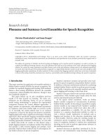
7.2. BER performance
ThecodedescribedinSection 6 was used to simulate the BER
performance of the iterative receiver with low computational
complexity. The blind phase estimator was used to estimate
and correct the phase disturbance present in each sub-block
of the received symbol vector, following which the phase-
corrected symbol vector was fed into the iterative receiver
in Figure 3. During the convergence phase, turbo phase
estimates were obtained once in 10 iterations (d
= 10). At
σ
Δ
= 2
◦
per symbol, Figure 7 shows the advantage of a blind
phase estimator in terms of BER performance. The result
compares three distinct cases with the normal receiver, where
turbo phase estimation was performed in every iteration.
The presence of blind phase estimator allows us to include
turbo phase estimator only once in every 10 iterations
with a small loss of 0.05 dB. However, without blind phase
estimator, performing turbo phase estimation only once in
every 10 iterations shows significant degradation. As shown,
the performance can be improved by including turbo phase
estimation for more iterations, particularly the early stages of
the decoder, during which the LDPC decoder provides a lot
of new information regarding the symbols.
8. CONCLUSION
In this paper, we addressed the problem of LDPC code-
based iterative decoding under phase noise channels from
a code perspective. We proposed construction of ring-based
codes for higher-order modulations that work well with sub-
block phase estimation techniques of low complexity. The
code was constructed using the new constraints outlined in
Section 3 such that it not only converges under sub-block
phase rotations, but also estimates them. We also showed the
property of ring-based check nodes under the presence of
phase ambiguity based on their edge gains in a generalized
manner. As part of our future work, we are looking at ways
to construct code without explicitly constructing local check
nodes for PAR. The sub-block size used in the simulation
results shown earlier, has not been optimized and we believe
that the method can be extended to adjust the observation
interval and phase model depending on the amount of phase
noise.
ACKNOWLEDGMENTS
The authors wish to acknowledge helpful discussions with
Dr. Steven S. Pietrobon on this topic and also thank reviewers
for their useful comments.
REFERENCES
[1] R. Gallager, “Low density parity-check codes,” IEEE Transac-
tions on Information Theory, vol. 8, no. 1, pp. 21–28, 1962.
[2] G. Colavolpe, A. Barbieri, and G. Caire, “Algorithms for
iterative decoding in the presence of strong phase noise,” IEEE
Journal on Selected Areas in Communications,vol.23,no.9,pp.
1748–1757, 2005.
[3] A. Barbieri, G. Colavolpe, and G. Caire, “Joint iterative
detection and decoding in the presence of phase noise
and frequency offset,” IEEE Transactions on Communications,
vol. 55, no. 1, pp. 171–179, 2007.
[4] I. Motedayen-Aval and A. Anastasopoulos, “Polynomial-
complexity noncoherent symbol-by-symbol detection with
application to adaptive iterative decoding of turbo-like codes,”
IEEE Transactions on Communications, vol. 51, no. 2, pp. 197–
207, 2003.
[5]R.NuriyevandA.Anastasopoulos,“Rotationallyinvariant
and rotationally robust codes for the AWGN and the non-
coherent channel,” IEEE Transactions on Communications,
vol. 51, no. 12, pp. 2001–2010, 2003.
[6] W. G. Cowley and M. S. C. Ho, “Transmission design for
Doppler-varying channels,” in Proceedings of the 7th Australian
Communications Theory Workshop (AusCTW ’06), pp. 110–
113, Perth, Australia, February 2006.
[7] M. Franceschini, G. Ferrari, R. Raheli, and A. Curtoni, “Serial
concatenation of LDPC codes and differential modulations,”
IEEE Journal on Selected Areas in Communications, vol. 23,
no. 9, pp. 1758–1768, 2005.
[8] S. Karuppasami and W. G. Cowley, “LDPC code-aided phase-
ambiguity resolution for QPSK signals affected by a frequency
offset,” in Proceedings of the 8th Australian Communications
Theory Workshop (AusCTW ’07), pp. 47–50, Adelaide, Aus-
tralia, February 2007.
[9]N.Noels,V.Lottici,A.Dejonghe,etal.,“Atheoretical
framework for soft-information-based synchronization in
iterative (turbo) receivers,” EURASIP Journal on Wireless
Communications and Networking, vol. 2005, no. 2, pp. 117–
129, 2005.
S. Karuppasami and W. G. Cowley 9
[10] S. Karuppasami, W. G. Cowley, and S. S. Pietrobon, “LDPC
code construction and iterative receiver techniques for chan-
nels with phase noise,” in Proceedings of the 67th IEEE
Vehicular Technology Conference (VTC ’08), Singapore, May
2008.
[11] D. Sridhara and T. E. Fuja, “LDPC codes over rings for
PSK modulation,” IEEE Transactions on Information Theory,
vol. 51, no. 9, pp. 3209–3220, 2005.
[12] M. C. Davey and D. MacKay, “Low-density parity check codes
over GF(q),” IEEE Communications Letters, vol. 2, no. 6, pp.
165–167, 1998.
[13] D. Declercq and M. Fossorier, “Decoding algorithms for
nonbinary LDPC codes over GF(q),” IEEE Transactions on
Communications, vol. 55, no. 4, pp. 633–643, 2007.
[14] A. Voicila, D. Declercq, F. Verdier, M. Fossorier, and P. Urard,
“Low-complexity, low-memory EMS algorithm for nonbinary
LDPC codes,” in Proceedings of IEEE International Conference
on Communications (ICC ’07), pp. 671–676, Glasgow, Scot-
land, UK, June 2007.
[15] S. ten Brink, G. Kramer, and A. Ashikhmin, “Design of low-
density parity-check codes for modulation and detection,”
IEEE Transactions on Communications, vol. 52, no. 4, pp. 670–
678, 2004.