Báo cáo hóa học: " Research Article Penetration Loss Measurement and Modeling for HAP Mobile Systems in Urban Environment Jaroslav Holis and Pavel Pechac" pot
Bạn đang xem bản rút gọn của tài liệu. Xem và tải ngay bản đầy đủ của tài liệu tại đây (893.98 KB, 7 trang )
Hindawi Publishing Corporation
EURASIP Journal on Wireless Communications and Networking
Volume 2008, Article ID 543290, 7 pages
doi:10.1155/2008/543290
Research Article
Penetration Loss Measurement and Modeling for
HAP Mobile Systems in Urban Environment
Jaroslav Holis and Pavel Pechac
Department of Electromagnetic Field, Czech Technical University in Prague, Technicka 2 Street, 166 27 Praha 6, Czech Republic
Correspondence should be addressed to Jaroslav Holis,
Received 1 October 2007; Accepted 2 April 2008
Recommended by Marina Mondin
The aim of this paper is to present the results of a measurement campaign focused on the evaluation of penetration loss into
buildings in an urban area as a function of the elevation angle. An empirical model to predict penetration loss into buildings
is developed based on measured data obtained using a remote-controlled airship. The impact on penetration loss of different
buildings and user positions within the buildings is presented. The measured data are evaluated as a function of the elevation
angle. The measurement campaign was carried out at 2.0 GHz and 3.5 GHz carrier frequencies, representing the frequency band
for high altitude platform third-generation mobile systems and, potentially, next generation mobile systems, mobile WiMAX, for
example, the new penetration loss model can be used for system performance simulations and coverage planning.
Copyright © 2008 J. Holis and P. Pechac. This is an open access article distributed under the Creative Commons Attribution
License, which permits unrestricted use, distribution, and reproduction in any medium, provided the original work is properly
cited.
1. INTRODUCTION
Urban areas are covered by a variety of mobile wireless
systems. One disadvantage of these systems is that they
are vulnerable to disasters—either natural or manmade
disasters such as terrorist attacks. To avoid this, terrestrial
networks could potentially be complemented with high
altitude platforms (HAPs) situated in the stratosphere at an
altitude of about 20 km [1]. HAPs can be promptly deployed
and easily change their locations. In addition, HAPs can
be located in multiple deployments [2]. A great benefit of
HAPs against terrestrial mobile networks is the absence of
shadowing for high elevation angles. HAP stations located in
the stratosphere offer noticeably lower free space loss than
satellites. Another benefit when compared to satellites is the
HAP position maintenance, with deviation of only 0.5 km
[3]. Based on these facts, it is obvious that HAPs can be
successfully used for urban outdoor coverage, but there is a
question of whether HAP can also provide mobile or wireless
services in general inside the buildings. Prospective mobile
systems for HAPs seem to be the third-generation universal
mobile telecommunication system (UMTS) operating in a
frequency band of about 2.0 GHz, which is also allocated
to HAPs [4], and the emerging mobile WiMAX systems
[5] operating in the frequency band between 2–6 GHz.
The problems of penetration loss inside the buildings is
a challenging area for HAP systems. Currently, an HAP
elevation-based empirical model has been published to
predict penetration loss into buildings at a frequency of
2.0 GHz for high elevation angles only [6, 7]. This model
applies to scenarios where the coverage of urban/suburban
areas is achieved at elevation angles ranging between 55–90
degrees and the HAP is positioned above the city center. In
[8], the authors studied the impact of high elevation angles
in the propagation mechanisms; it was shown that in urban
coverage scenarios by HAPs most of the buildings have at
least one of the walls and the rooftop directly illuminated.
The propagation prediction model for terrestrial systems
is not defined as a function of the elevation angle [9, 10],
which is the crucial parameter in the case of the HAP
systems. The aim of this paper is to introduce a novel
empirical model of penetration loss inside buildings in urban
areas as a function of the elevation angle developed based
on empirical data obtained from trials using a remote-
controlled airship. The remote-controlled airship was used
to measure penetration loss inside the buildings because of
its perfect flight control possibilities (so that a whole range
of elevation angles can be observed). The measurements
were carried out in different types of buildings, at different
positions, at different heights, and at frequencies of 2.0 GHz
2 EURASIP Journal on Wireless Communications and Networking
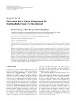
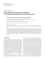
Figure 1: Remote-controlled airship.
and 3.5 GHz. The ray tracing approach was not used here
since the scenarios are very complicated to describe, and the
aim of this paper is to develop a universal model applicable
to urban areas rather than a detailed description of a single
concrete situation.
The second section of this paper describes the measure-
ment campaign, introduces details about the airship used,
the developed payload, the antennas, and the considered
scenarios. The third section deals with the processing of
the measured data. A novel, universal empirical model is
introduced as a function of the elevation angle. During the
measurements, the airship was flying over a building in
various directions in order to obtain results statistically inde-
pendent on the azimuth angle and so the final model is not a
function of the azimuth angle. The final section discusses the
applicability of a universal model at frequencies of 2.0 and
3.5 GHz. In addition, this model can be successfully used for
planning of prospective HAP mobile systems in S band.
2. MEASUREMENT CAMPAIGN
The measurement campaign was planned in different types
of buildings and using selected scenarios in the center of the
city of Prague. A statistical analysis of the collected data was
then performed as a function of the elevation angle.
2.1. The remote-controlled airship
A remote-controlled airship [11] was utilized to carry the
transmitters. This airship (see Figure 1) is designed to be low
altitude, but for the trial we have presented here it is not
necessary to reach the stratosphere. The key point is to obtain
asufficient range of elevation angles during the trial. This
requirement excellently suits the remote-controlled airship,
which offers the great benefit of flexible manoeuvrability. The
main parameters of the airship used for the experiment are
as follows:
(i) length 9 m,
(ii) maximum diameter 2.3 m,
(iii) payload 7 kg,
(iv) hull filling helium.
The altitude is limited by visual contact with the operator
at this stage of airship development. The altitude fluctuated
by hundreds of metres during the experiments. Another
significant benefit of the airship for the trial is the possibility
it offers of fast and simple transportation.
During the measurements, the airship was flying over a
building in various directions in order to obtain results statis-
tically independent on the azimuth angle. Small movements
of airship were compensated using a special stabilization
platform to equalize inclinations caused by wind gusts.
2.2. Penetration loss measurement
The measurement campaign was planned and executed in
the following way. The signal was transmitted from the
airship and received inside a building. The special payload
designed for this trial was mounted in the airship gondola.
Continuous wave (CW) generators with an output power
of 26 dBm and rectangular patch antennas were used to
transmit the signal. The carrier frequencies were equal to
2.0 GHz and 3.5 GHz. These frequencies represent the central
value of the carrier frequency for the third-generation mobile
services UMTS and mobile WiMAX systems.
The receiver station was composed of a spectrum ana-
lyzer and a spiral broadband antenna (circular polarization)
receiving the signal. The receiving antenna was situated
1.5 m above the floor and 2 m in front of a wall. The wide
beamwidth antennas were utilized for this trial in order
to minimize the effect of antenna radiation patterns on
the interpretation of propagation effects. The possible error
caused by antennas was lower than 3 dB. The position of
the airship was recorded using the global positioning system
(GPS), and the altitude of the airship was measured based
on a barometer, which provides more accurate information
concerning the altitude. The airship position determines the
distance between the receiver station and the transmitter
antennas. The penetration loss can then be calculated from
the measured received signal level separating the impact
of free space loss (FSL) and the measurement system
(antenna gain, transmitted signal level, cable losses, etc.). The
penetration loss is usually defined as the difference between
the mean received signal strength in the surroundings of a
building and the mean signal strength inside the building. In
this paper, the penetration loss is defined as the additional
path loss with respect to the FSL from the transmitter up to
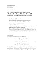
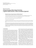
the building. Figure 2 presents an example of received signal
level during the measurement at a frequency of 2.0 GHz in
the ground floor of an office building during two flyovers of
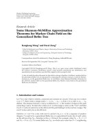
the airship above the building. Figure 3 illustrates the path
loss in addition to FSL from the measured signal level. It
is obvious from Figure 3 that the additional path loss lies
in the range 10–60 dB depending on the airship’s position
(lower additional path loss was obtained for higher elevation
angles and in a situation where the HAP directly illuminated
the wall neighboring the receiver station). The very high
additional path loss was measured for very low elevation
angles, where there is a high probability that the signal is
incoming across more walls inside the building, and other
propagation effects such as shadowing and diffraction on
surrounding buildings affect the final signal level.
2.3. Selected scenarios
Measurements were carried out in four different types of
buildings:
J. Holis and P. Pechac 3
5004003002001000
Measured samples (
−)
−40
−50
−60
−70
−80
−90
−100
−110
−120
Received signal level (dBm)
Received signal level at 2 GHz for flights over an office building
Figure 2: An example of measured received signal level at 2.0 GHz.
(i) an office building,
(ii) an office building with storeys higher than surround-
ing buildings,
(iii) a brick building,
(iv) a prefab residential building.
In addition, the receiver station was situated in different
typical positions inside the buildings. It will be shown that
the resulting penetration loss is crucially dependent on the
receiver position within the building. One of the selected
positions of the receiver station was, for example, 2 m in
front of the external wall, and another in the middle of the
building and distant from directly illuminated external walls,
and so forth. The storey number influences the penetration
loss as well, but the impact of the floor level was not
as crucial as the position of the receiving station within
the floor. More than 50 000 measured samples were used
for further processing. About 5 samples per second were
collected during measurements.
3. PENETRATION LOSS
This section described the processing of the measurement
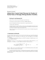
results. Figure 4 shows an example of the processed data
measured on the second floor of an office building at
2.0 GHz. The measured samples were averaged in 1 degree
step of the elevation angle. A histogram of measured data for
the elevation angle of 33 degrees is shown inside Figure 4.
The receiver station was situated 2 metres in front of an
external wall. The dependence of the penetration loss in
decibels (dB) on the elevation angle (θ) can be found by the
following function:
L
PL
(θ) =
a − b(θ − c)
2
,(1)
where a, b,andc are empirical parameters.
The measurement was carried out in the same position
three floors above the ground floor. All of these floors are
below the rooftop level of surrounding buildings in the area.
5004003002001000
Measured samples (
−)
70
60
50
40
30
20
10
0
Penetration loss (dB)
Penetration loss at 2 GHz for flights over an office building
Figure 3: An example of extracted penetration loss into the ground
floor of an office building.
908070605040302010
Elevation angle (
◦
)
60
50
40
30
20
10
0
Penetration loss (dB)
Measured penetration loss inside an office
building-2nd floor, f
= 2GHz
Measured data
Fitted data
500
0
2
4
6
Penetration loss (dB)
Count (−)
Figure 4: Penetration loss as a function of the elevation angle on
the second floor of an office building at 2.0 GHz.
The fitted measured data are presented in Figure 5.Thevery
similar dependence of the penetration loss on the elevation
angle is distinguishable from Figure 5.
Lower penetration loss was measured at the higher floors
for some elevation angles. The multipath propagation plays
an important role here, so that the lowest penetration loss
for higher elevation angles was measured on the first floor.
Nevertheless, differences in penetration loss were not as
crucial in this measurement scenario. In order to obtain a
universal model, all the data from this measurement sce-
nario were processed together. The final dependence of the
penetration loss on the elevation angle in the office building
for storeys situated below the rooftop level of surrounding
4 EURASIP Journal on Wireless Communications and Networking
908070605040302010
Elevation angle (
◦
)
60
50
40
30
20
10
0
Penetration loss (dB)
Penetration loss inside an office building, f = 2GHz
Ground floor
1st floor
2nd floor
3rd floor
Figure 5: Penetration loss as a function of the elevation angle for
range of floors in office building, f
= 2.0GHz.
908070605040302010
Elevation angle (
◦
)
60
50
40
30
20
10
0
Penetration loss (dB)
Measured penetration loss inside an office building, f = 2GHz
Measured data
Fitted data
Figure 6: Mean penetration loss as a function of the elevation angle
in office building at 2.0 GHz.
buildings is depicted in Figure 6. The corresponding empir-
ical parameters for model (1) are summarized in Table 1.
This dependence can easily be used in system level simulation
for the planning of a wireless system provided using HAP
stations.
In the second scenario, the receiver station was situated
in the same office building, but in the floors above the
rooftop level of surrounding buildings. In this case, the effect
of multipath propagation is not so dominant as the signal
cannot reflect from neighboring buildings and so forth. The
measured data were again successfully approximated by (1).
The results for the four floors are shown in Figure 7.
908070605040302010
Elevation angle (
◦
)
60
50
40
30
20
10
0
Penetration loss (dB)
Measured penetration loss inside the office building, f = 2GHz
5th floor
6th floor
7th floor
8th floor
Figure 7: Penetration loss as a function of the elevation angle for a
range of floors in an office building, f
= 2.0GHz.
In the 6th and 7th floors, a higher penetration loss was
measured than in the 5th floor because the reflections from
surrounding buildings can be still dominant for the 5th floor.
The atypical behavior in the 8th floor is given by the position
of the receiver station (directly under the flat roof of the
building being studied), and by the fact that the 8th floor
is a superstructure with smaller floor projection than the 7th
floor so that the signal can reflect from the 7th floor roof rim.
In another scenario, the receiver station was situated in 7
floors of a prefab residential building. It was placed in the
corridor in the middle of the building so that the rooms
were symmetrically located around the receiver station,
meaning that the receiver station was as far as possible
from the external walls. For this measurement scenario,
the penetration loss at 2.0 GHz was about 50 dB almost
independently of the elevation angle. The mean measured
value for the receiver station situated in the middle of the
residential building is depicted in Figure 8. Figure 8 shows
the impact of the type of building and the receiver position
inside the building on the penetration loss.
The penetration loss into an older building built of bricks
was also measured. The receiver station was situated 2 m
from an external wall. The data measurement was divided
to cover two situations. In the first, the external wall, in
front of which the receiver station was located, was directly
illuminated by the transmitter. In the second, the external
wall was not directly illuminated, that is, the airship was
situated on the opposite side of the building. The results of
this study are presented in Figure 9. For the situation where
the external wall was directly illuminated, the penetration
loss decreased for higher elevation angles. On the other
hand, the penetration loss increases for a decreasing angle
of elevation in the case of external wall that was not directly
illuminated. The empirical model for high elevation angles
[6] assumes that the external wall is directly illuminated.
J. Holis and P. Pechac 5
908070605040302010
Elevation angle (
◦
)
60
50
40
30
20
10
0
Penetration loss (dB)
Measured penetration loss in different buildings, f = 2GHz
Below roof-top level
Above roof-top level
In the middle of building
Figure 8: Penetration loss as a function of the elevation angle for
different scenarios, f
= 2.0GHz.
This assumption significantly simplifies the calculation. In
any event, there is a high level of agreement between the data
measured in the case of a directly illuminated wall and the
empirical model [6] for the high elevation angle, but this
model does not consider the scenario of a wall that is not
directly illuminated, which has a crucial impact on the final
signal level. The final dependence for all data measured in
the brick building has similar shape of curve to Figure 6,for
example.
Finally, the impact of the carrier frequency was also
studied. The trial was accomplished at frequencies of 2.0 GHz
and 3.5 GHz. It is obvious that the penetration loss is
higher for the higher frequencies. The behavior of the
penetration loss dependence on an elevation angle was found
to be almost the same at 2.0 and 3.5 GHz. The increase of
penetration loss at 3.5 GHz compared to 2.0 GHz depends
on the type of building. For an office building where metal
frames are used, the penetration loss at 3.5 GHz is about
5.0 dB higher than for a frequency of 2.0 GHz. In the
residential building, a difference in penetration loss of 2.3 dB
was found. This trend concords with the measurements
carried out for terrestrial systems [9].
Figure 10 illustrates the comparison of penetration losses
as a function of the elevation angle for both frequencies and
two types of buildings. For more clarity, only a fitted curve is
shown for 2.0 GHz.
The aim of this work was to explore the behavior of
penetration loss into the building as a function of the
elevation angle in urban areas for HAP systems. The different
behavior of penetration loss dependence on the elevation
angle was observed in different scenarios. This means that for
precise modeling model (1) should be calibrated according to
the specific scenarios. Anyway, the final universal model as a
function of the elevation angle was determined based on the
908070605040302010
Elevation angle (
◦
)
60
50
40
30
20
10
0
Penetration loss (dB)
Measured penetration loss inside the building, f = 2GHz
Indirectly illuminated wall
Directly illuminated wall
Final fitting
Empirical model [6]
Figure 9: Penetration loss as a function of the elevation angle for
different scenarios at 2.0 GHz.
908070605040302010
Elevation angle (
◦
)
60
50
40
30
20
10
0
Penetration loss (dB)
Pen. loss in office (in front of window) and
residential (in the middle) buildings
Residential building, f
= 3.5GHz
Residential building, f
= 2GHz
Office building, f
= 3.5GHz
Office building, f
= 2GHz
Figure 10: Comparison of penetration loss as a function of the
elevation angle for different environments and carrier frequencies
of 2.0 GHz and 3.5 GHz.
all measured data from the most common scenarios:
L
PL
(θ) =
⎧
⎪
⎪
⎨
⎪
⎪
⎩
506 + 0.512(θ − 70.4)
2
, f = 2.0 GHz,
692 + 0.571(θ − 70.2)
2
, f = 3.5GHz.
(2)
The empirical parameters for (1) are summarized for
different environments in Ta ble 1 including the final model.
6 EURASIP Journal on Wireless Communications and Networking
Table 1: Parameters of the penetration loss model for different environments and frequencies in an urban area.
Office building
Brick building Final
Below rooftop level Above rooftop level
2.0 GHz
a 444 1443 550 506
b
−0.802 −0.296 −0.252 −0.512
c 68.1 56.3 77.2 70.4
3.5 GHz
a 723 1858 664 692
b
−0.960 −0.324 −0.251 −0.571
c 67.5 54.8 79.0 70.2
908070605040302010
Elevation angle (
◦
)
60
50
40
30
20
10
0
Penetration loss (dB)
Final penetration loss model in urban environment
f
= 3.5GHz
f
= 2GHz
Empirical model at 2 GHz [6]
Figure 11: Comparison of the new penetration loss model with an
empirical model developed for high elevation angles in [6].
4. DISCUSSION
The penetration loss as a function of the elevation angle was
measured using a remote-controlled airship. The campaign
was motivated by a lack of penetration models for HAP
systems with the exception of an empirical model for
building penetration loss at 2.0 GHz for high elevation angles
[6]. This model was developed for a scenario, where the 2
walls of a room with the receiver are directly illuminated.
This condition is very hard to achieve, especially for lower
elevation angles below 60 degrees. As shown above, the
penetration loss closely depends on the position of the
HAP and the receiver position within a building. Based on
the measurement data, a model was developed for typical
scenarios in urban areas. The penetration loss calculated
using (2) is shown in Figure 11 and compared with the
empirical model for high elevation angles [6]. Difference in
penetration loss at 2.0 GHz and 3.5 GHz is about 3.6 dB, but
it depends on building material. Generally, it could be from
1to6dB[12].
The total propagation loss for HAP mobile systems when
the mobile terminal is situated inside a building can be
determined based on the free space loss and the empirical
penetration loss model (2):
L
= L
FSL
+ L
PL
,(3)
where L
FSL
is the free space loss in dB, and L
PL
is the
penetration loss in dB defined in (2). The free space loss is
equal to
L
FSL
= 20 log
d
km
+20log
f
GHz
+92.4, (4)
where f
GHz
is the carrier frequency in GHz, and d
km
is the
distance between a platform and a user in km.
For more realistic approach, an additional random log-
normal fade margin should be added as a location variability.
The standard deviation of the log-normal distribution for
indoor environment is about 10 dB.
The multipath fading was eliminated thanks to the
averaging of the narrowband measurement data. It is obvious
that due to the measurement in real urban scenarios the
multipath propagation effects and, especially in case of low
elevation angles, the shadowing of surrounding buildings
play an important role. We have not tried to distinguish
the different components of the propagation phenomena
since the goal was to model the average signal level for
an indoor mobile station served from HAPs regardless the
azimuth angle. This way the introduced penetration loss
model can be, together with information such as the type
of building and construction material used that collectively
define a street model [13], successfully utilized for simple
propagation predictions in urban areas for HAP scenarios.
This model could be used for system level simulations of
mobile services provided via HAPs.
5. CONCLUSION
An empirical propagation prediction model for calculation
of penetration loss into the building as a function of the
elevation angle is presented in this paper. The model was
developed based on measured data obtained using a remote-
controlled airship. It is shown that the penetration loss
closely relates to the position of the user within the building
as well as to the type of building. The measured data
were approximated by a simple function given by three
empirical parameters depending on the type of building and
the frequency. The universal model was derived from the
statistical processing of data obtained in different scenarios
J. Holis and P. Pechac 7
based on measurements for four building types in the Czech
Republic. Further calibration may be needed for the model to
be applied in other specific scenarios. This model can be used
for the radio network planning of mobile systems provided
via high altitude platforms in the whole range of elevation
angles.
ACKNOWLEDGMENT
This work was partly supported by the Czech Ministry of
Education, Youth and Sports under projects OC092-COST
Action 297 and MSM 6840770014.
REFERENCES
[1] T. C. Tozer and D. Grace, “High-altitude platforms for wireless
communications,” Electronics & Communications Engineering
Journal, vol. 13, no. 3, pp. 127–137, 2001.
[2]D.Grace,J.Thornton,G.Chen,G.P.White,andT.C.
Tozer, “Improving the system capacity of broadband services
using multiple high-altitude platforms,” IEEE Transactions on
Wireless Communications, vol. 4, no. 2, pp. 700–709, 2005.
[3] “Revised technical and operational parameters for typical
IMT-2000 terrestrial systems using High Altitude Platforms
Stations and CDMA radio transmission technologies,” ITU-R
Study Groups Document 8-1/307-E, ITU, March 1999.
[4] “Minimum performance characteristics and operational con-
ditions for high altitude platform stations providing IMT-
2000 in the Bands 1885–1980 MHz, 2010–2025 MHz and
2110–2170 MHz and in Regions 1 and 3 and 1885–1980 MHz
and 2110–2160 MHz in Region 2,” Recommendation ITU-R
M.1456, ITU, 2000.
[5] “Air interface for fixed and mobile broadband wireless access
systems—Amendment for physical and medium access con-
trol layers for combined fixed and mobile operation in licensed
band,” IEEE Standard 802.16e-2005, 2005.
[6] D. I. Axiotis and M. E. Theologou, “An empirical model
for predicting building penetration loss at 2 GHz for high
elevation angles,” IEEE Antennas and Wireless Propagation
Letters, vol. 2, no. 1, pp. 234–237, 2003.
[7] D. I. Axiotis and M. E. Theologou, “Building penetration
loss at 2 GHz for mobile communications at high elevation
angles by HAPS,” in Proceedings of the 5th I EEE International
Symposium on Wireless Personal Multimedia Communications
(WPMC ’02), vol. 1, pp. 282–285, Honolulu, Hawaii, USA,
October 2002.
[8] D. I. Axiotis and M. E. Theologou, “2 GHz outdoor to indoor
propagation at high elevation angles,” in Proceedings of the
13th International IEEE Symposium on Personal, Indoor and
Mobile Radio Communications (PIMRC ’02), vol. 2, pp. 901–
905, Lisbon, Portugal, September 2002.
[9] S. R. Saunders and A. Argo-Zavala, Antennas and Propagation
for Wireless Communication Systems, John Wiley & Sons, New
York, NY, USA, 2nd edition, 2007.
[10] COST 231 Final report, “Digital Mobile Radio: COST 231
VIEW on the Evolution Towards 3rd Generation Systems,”
Commission of the European Communities and COST
Telecommunications, Brussels, Belgium, 1999.
[11] />[12] S. Aguirre, L. H. Loew, and Y. Lo, “Radio propagation into
buildings at 912, 1920, and 5990 MHz using microcells,”
in Proceedings of the 3rd Annual International Conference on
Universal Personal Communications (ICUPC ’94), pp. 129–134,
San Diego, Calif, USA, September-October 1994.
[13] J. Holis and P. Pechac, “Elevation dependent shadowing model
for mobile communications via high altitude platforms in
built-up areas,” IEEE Transactions on Antennas and Propaga-
tion, vol. 56, no. 4, pp. 1078–1084, 2008.