Báo cáo hóa học: " Research Article Combining OOK with PSM Modulation for Simple Transceiver of Orthogonal Pulse-Based TH-UWB Systems" potx
Bạn đang xem bản rút gọn của tài liệu. Xem và tải ngay bản đầy đủ của tài liệu tại đây (900.43 KB, 11 trang )
Hindawi Publishing Corporation
EURASIP Journal on Wireless Communications and Networking
Volume 2008, Article ID 735410, 11 pages
doi:10.1155/2008/735410
Research Article
Combining OOK with PSM Modulation for Simple Transceiver
of Orthogonal Pulse-Based TH-UWB Systems
Sudhan Majhi,
1
A. S. Madhukumar,
1
A. B. Premkumar,
1
and Paul Richardson
2
1
School of Computer Engineering, Nanyang Technological University, Block-N4, Nanyang Avenue, Singapore 639798
2
Electrical and Computer Engineering, University of Michigan, Dearborn, MI 48128, USA
Correspondence should be addressed to Sudhan Majhi,
Received 21 November 2007; Revised 2 June 2008; Accepted 22 July 2008
Recommended by Weidong Xiang
This paper describes a combined modulation scheme for time-hopping ultra-wideband (TH-UWB) radio systems by using on-
off keying (OOK) and pulse-shape modulation (PSM). A set of orthogonal pulses is used to represent bits in a symbol. These
orthogonal pulses are transmitted simultaneously in the same pulse repetition interval resulting in a composite pulse. This
scheme transmits the same number of bits by using fewer orthogonal pulses and receiver correlators than those used in PSM and
biorthogonal PSM (BPSM). The proposed scheme reduces multiple-access interference and multipulse interference considerably
by using crosscorrelation properties of orthogonal pulses. Since each bit is individually received by OOK, the proposed scheme
requires less power. Hence, it is applicable for energy constrained and low-cost TH-UWB systems. The bit-error-rate (BER)
performance is analyzed both mathematically and through computer simulations under the different channel environments. The
performance of this scheme is compared with that of existing PSM and its combined modulation schemes by using two sets of
orthogonal pulses.
Copyright © 2008 Sudhan Majhi et al. This is an open access article distributed under the Creative Commons Attribution License,
which permits unrestricted use, distribution, and reproduction in any medium, provided the original work is properly cited.
1. INTRODUCTION
The successful deployment of ultra-wideband (UWB) radio
systems for high-speed indoor communication strongly
depends on the development of pulses, modulation tech-
niques, and low-complexity receivers. For time-hopping
ultra-wideband (TH-UWB) systems, symbols are transmit-
ted using short-analog waveforms confined to the power and
spectrum range specified for UWB radios [1]. Various kinds
of modulation schemes such as pulse-position modulation
(PPM), orthogonal PPM (OPPM), pulse-amplitude modula-
tion (PAM), on-off keying (OOK), and biphase modulation
(BPM) have been proposed for TH-UWB radio to achieve
better system performance and high data rate transmission
[2, 3]. However, due to increased intersymbol interference
(ISI) in the presence of multipath channel, M-ary PPM or
M-ary orthogonal PPM (OPPM) for TH-UWB systems may
not be an effective modulation scheme for higher values
of M [4, 5]. M-ary PAM also has limited applications for
any short-range and low-power communication systems [6].
Although the OOK scheme is easy-to-implement, it cannot
be used for higher-level modulation schemes for high data
rates due to its binary nature.
Due to its robustness against ISI and multiple-access
interference (MAI), PSM is an interesting research topic
in TH-UWB, direct sequence UWB (DS-UWB), and trans-
mitted reference UWB (TR-UWB) radio systems [7–10].
However, due to speculative autocorrelation property of
higher-order orthogonal pulses, PSM cannot be used for
higher-level modulation schemes for improving system data
rate. Moreover, it requires a large number of receiver
correlators and system complexity increases nonlinearly with
increasing M.
To address these problems, combined with PSM schemes
such as biorthogonal PSM (BPSM), BPSK-PSM, and 2PPM-
PSM have been proposed to transmit the same amount of
data using fewer orthogonal pulses and receiver correlators
[11–14]. However, biorthogonal PSM requires M/2 orthog-
onal pulses and receiver correlators. BPSK-PSM scheme
is a polarity-dependent modulation scheme. Designing an
antipodal signal for orthogonal pulses is more difficult
compared to nonantipodal signal [15]. 2PPM-PSM requires
coded modulation to maintain orthogonality of constellation
vectors and needs external memory in the receiver to
improve system performance. OPPM-BPSM is a combined
modulation scheme that was proposed for high data rates
2 EURASIP Journal on Wireless Communications and Networking
[16]. However, this scheme does not reduce the number
of receiver correlators, resulting in high system complexity.
Moreover, most of these combined schemes have been ana-
lyzed in AWGN environment and have not been considered
in multipath channel environments [12, 13].
To deal with these challenges, a combined modulation
scheme based on OOK and PSM for M-ary modulation
schemes was proposed to reduce system complexity by
using OOK for higher-level modulation schemes [14].
This preliminary work was based on an AWGN channel,
and interference reduction was seen only in MAI. In this
paper, multipath environments are considered by using
two different sets of orthogonal pulses. Due to multipath
and pulse orthogonality, two interference terms, interpulse
interference (IPI) and multipulse interference (MPI), are
considered in place of ISI. The cross-correlation properties
of the orthogonal pulses reduce MPI, improving the sys-
tem performance in multipath scenarios when compared
to single-pulse systems. The present paper discusses the
details of transceiver structure for an OOK-PSM system, its
performance, and a detailed interference modeling under
multipath scenarios. To compare it with existing schemes,
PSM and its combined modulation schemes are also analyzed
using a multipath channel [4].
This paper is organized as follows. Section 2 describes
OOK-PSM modulation scheme and its advantages. Section 3
discusses transmission and detection procedures with the
assumedcorrelatorreceiverstructure.Section 4 shows inter-
ference issues and system performance of OOK-PSM scheme
using RAKE reception. Section 5 discusses the simulation
results under different channel environments in the presence
of multiple users.
2. PROPOSED COMBINED MODULATION SCHEME
The proposed method maps a set of message bits or symbol
onto one or several orthogonal pulses by on-off keying. The
number of pulses in each symbol depends on the number of
non-zero bits in the symbol. Ta b le 1 shows examples of 2-
bit and 3-bit symbol transmissions and the corresponding
transmitted pulses. In general, N-bit symbol requires N
orthogonal pulses to transmit OOK-PSM signals. These N
independent bits are sent at the same time by assigning dif-
ferent orthogonal pulses resulting in a composite pulse. The
presence of individual orthogonal pulses in the composite
pulse is decided by on-off keying, (i.e., pulse is present for
one and is absent for zero). Since pulses are orthogonal, they
overlay in both time and frequency domains without any
interference [17].
The composite pulse passes through a set of correlators in
the receiver. The receiver correlators are designed using a set
of template signals which are similar to the set of orthogonal
pulses used in the transmitter. Each correlator recovers a
pulse from the composite pulses by exploiting its correlation
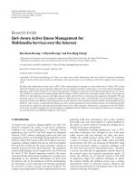
properties. The composite pulses for 3-bit symbols are shown
in Figure 1.
The proposed method has several advantages over con-
ventional methods. For example, it uses fewer orthogonal
pulses and receiver correlators than those used in PSM and
Table 1: Transmitted pulses for 2-bit and 3-bit symbols.
Schemes
T
f
Combined form of
transmitted pulses
w
0
(t) w
1
(t) w
2
(t)
2-bit
00 Off Off Off
None
01 Off Off On
w
2
(t)
10 Off On Off
w
1
(t)
11 Off On On
w
1
(t)+w
2
(t)
3-bit
000 Off Off Off
None
001 Off Off On
w
2
(t)
010 Off On Off
w
1
(t)
011 Off On On
w
1
(t)+w
2
(t)
100 On Off Off
w
0
(t)
101 On Off On
w
0
(t)+w
2
(t)
110 On On Off
w
0
(t)+w
1
(t)
111 On On On
w
0
(t)+w
1
(t)+w
2
(t)
×10
−8
21.510.50
Time (s)
111110101100011010001000
−2
−1.5
−1
−0.5
0
0.5
1
1.5
2
×10
−6
Amplitude (v)
Composite pulse waveforms
Figure 1: Composite MHPs for a 3-bit OOK-PSM modulation
scheme.
biorthogonal PSM schemes. This leads to lower complexity
for system design. Since zero is represented by absence of
pulse, the proposed scheme uses low average transmit power,
which is critical for energy-constrained UWB communica-
tion systems. Further, complexity of OOK is nearly half of
that of other conventional modulation schemes and is easier-
to-implement. This complexity reduction and simplicity are
applicable when OOK is combined with other modulation
schemes.
Since the proposed scheme uses orthogonal pulses, MAI
can be reduced considerably by assigning different subsets
of orthogonal pulses for different users. MPI is also reduced
by using cross-correlation properties of orthogonal pulses.
Moreover, it transmits more bits using fewer orthogonal
pulses, it generates fewer spectral spikes in the signal [12].
Therefore, the proposed scheme can coexist with overlapping
narrowband systems without causing significant interference
[18]. The overall scheme is downward compatible. That is
Sudhan Majhi et al. 3
a
i
∈{0, 1}
a
0
, a
1
, , a
N−1
Tr an sm it te d
symbol
S/P
w
0
(t)
w
1
(t)
w
i
(t)
.
.
.
w
N−1
(t)
s(t)
=
a
i
w
i
(t)
+
Tx Rx
w
0
(t)
w
1
(t)
w
i
(t)
.
.
.
w
N−1
(t)
Z
N−1
.
.
.
Z
0
>
<
>
<
>
<
.
.
.
>
<
a
0
a
1
a
i
a
N−1
P/S
a
0
, a
1
, , a
N−1
Received
symbol
Figure 2: Correlation transceiver structure for N-bit OOK-PSM modulation scheme in AWGN channel.
and hence the higher-level modulation schemes can be used
for lower level modulation systems without changing the
hardware design. For example, 3-bit scheme can be changed
into 2-bit scheme by just keeping off w
0
(t) or changed into
binary scheme by keeping off w
0
(t)andw
1
(t). This property
can be exploited further for adaptive modulation systems
based on channel conditions at any given instant.
For multiple-access systems, design of transmitted signal
depends on the modulation scheme and TH-codes to
avoid catastrophic collision among users. The OOK-PSM
modulation signal of the kth user for the ith symbol can be
defined as
s
(k)
i
(t) =
E
(k)
tx
N
s
−1
j=0
a
i
w
(k)
t − jT
f
− c
(k)
j
T
c
,(1)
where i
= 0, 1, , M−1, N
s
is the number of pulse repetition
interval for a symbol, E
(k)
tx
is the transmitted energy of kth
user, T
f
is the pulse repetition interval, index j represents
the number of pulse repetition intervals for a symbol, c
(k)
j
is
the TH sequence with chip duration T
c
,and
w
(k)
(t) =
w
(k)
0
(t)w
(k)
1
(t) ···w
(k)
N
−1
(t)
T
(2)
is the N-dimensional column vector of kth user, w
(k)
n
(t) is the
nth-order orthogonal pulse of kth user, and a
i
is the N-bit
binary row data vector for the ith symbol.
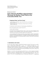
3. PERFORMANCE OF OOK-PSM IN AWGN CHANNEL
The system performance and receiver structure depend on
modulation schemes and channel models. In this section,
system performance is analyzed with the assumed correlator
receiver structure. Correlator-based transceiver structure for
N-bit OOK-PSM modulation scheme is shown in Figure 2.
ThecorrelatorreceivercontainsN correlators for N-bit
OOK-PSM scheme. Since the system supports N
u
users, the
received signal in additive white Gaussian noise (AWGN)
channeliswrittenas
r(t)
=
N
u
k=1
E
(k)
rx
s
(k)
t − τ
(k)
+ n(t), (3)
where τ
(k)
is the time delay for kth user, E
(k)
tx
is the received
energy of kth user, and n(t) is the AWGN, assumed to have a
two-sided power spectral density of N
0
/2. The received signal
passes through N correlators. In each correlator, the received
signal is multiplied by template signal and the correspond-
ing transmission bit is decided by exploiting correlation
properties of the orthogonal pulses. Hard decision decoding
is assumed at the correlator to detect a bit, followed by
a parallel-to-serial converter to detect a symbol. However,
the receiver performance can be improved by using high-
performance soft-decision decoding method.
The number of correlators in the receiver is the same
as the number of bits in a symbol. If N
s
is the number of
repetition interval for a symbol, the reference bit b is defined
in the time interval [0, T
b
], where T
b
= N
s
T
f
. The decision
statistic of user 1 is
y
=
T
b
0
r(t)w
(1)
t − jT
f
− c
(1)
j
T
c
dt
=
N
u
k=1
T
b
0
E
(k)
rx
s
(k)
t−τ
(k)
+n(t)
w
(1)
t− jT
f
−c
(1)
j
T
c
dt
=
Z
0
Z
1
··· Z
N−1
T
,
(4)
where w
(1)
(t) is the template signals defined in (2), neglecting
transceiver derivative characteristics and Z
l
is the test statistic
of lth correlator which undergoes a hard decision decoding,
where l
= 0, 1, , N − 1. The value of Z
l
can be expressed as
Z
l
= Z
l,s
+ Z
l,MAI
+ Z
l,n
,(5)
4 EURASIP Journal on Wireless Communications and Networking
×10
−9
10.50−0.5−1
Time (s)
1st order Hermite
2nd order Hermite
3rd order Hermite
−1
−0.8
−0.6
−0.4
−0.2
0
0.2
0.4
0.6
0.8
1
Amplitude
Autocorrelation of Hermite pulses of order 1, 2 and 3
Figure 3: Autocorrelation values of short duration MHPs of 1st-,
2nd-, and 3rd-order pulses.
where Z
l,s
is the desired signal, Z
l,MAI
is the MAI term, and
Z
l,n
is the AWGN term at the lth correlator. Each of these
terms are explained in the following paragraphs.
Assuming perfect synchronization, desired signal Z
l,s
can
be expressed as
Z
l,s
=
N
s
−1
j=0
jT
f
+c
(1)
j
T
c
+T
c
jT
f
+c
(1)
j
T
c
E
(1)
rx
s
(1)
(t)w
l
t − jT
f
− c
(1)
j
T
c
dt,
(6)
where w
l
(t) is the template signal of lth correlator. The useful
pulse of the desired user takes place within the chip duration
T
c
, so the time frame [jT
f
,(j +1)T
f
] changes into [jT
f
+
c
(1)
j
T
c
, jT
f
+ c
(1)
j
T
c
+ T
c
]. Assuming that an lth-order pulse is
present in the composite pulse, the signal energy of the user
1 at the lth correlator for N
s
time frame is obtained by
E
(1)
b
=
Z
l,s
2
= E
(1)
rx
N
2
s
T
c
0
h
2
l
(t)dt = E
(1)
rx
N
2
s
,(7)
where E
(k)
rx
is the received amplitude of the kth user.
Under standard Gaussian approximation, Z
l,n
and Z
l,MAI
are assumed to be zero-mean Gaussian random processes
as characterized by variances σ
2
n
and σ
2
MAI
,respectively.Due
to timing jitter (
) error from N
u
− 1 interfering users,
is uniformly distributed over [Δ, −Δ], where Δ = 0.1
nanosecond for modified Hermite pulses (MHPs) up to 4th
order [7, 19, 20]. The total MAI at lth correlator Z
l,MAI
can
be expressed as [21]
Z
l,MAI
=
N
u
k=2
N
s
−1
j=0
(j+1)T
f
jT
f
s
(k)
t − τ
(k)
−
w
l
t − jT
f
− c
(1)
j
T
c
dt.
(8)
As the timing jitter error from interfering user is very small
when compared to τ
(k)
∈ [0, N
s
T
f
], one can assume that
τ
(k)
+ ≈ τ is uniformly distributed over the interval
[0, N
s
T
f
]. Therefore, the total interference energy from other
users can be evaluated as
σ
2
l,MAI
=
N
s
T
f
N
u
k=2
T
f
0
E
(k)
rx
T
p
0
w
(k)
n
(t − τ)w
l
(t)dt
2
dτ,
(9)
where T
p
is the width of pulses, w
(k)
n
is the nth-order pulses
from the kth user. If all users use the same set of orthogonal
pulses, n takes any value from the set
{0, 1, , N − 1} and
if all users use different exclusive orthogonal subsets, n is not
equal to l,wherel is the order of pulse waveform of user 1 and
is used at the lth correlator. It can be assumed that E
(1)
rx
=
E
(2)
rx
= ··· = E
(N
u
)
rx
= E
rx
for perfect power control for all
users. Since correlation value depends on the width of the
pulses, (9) can be expressed as
σ
2
l,MAI
=
N
s
T
f
E
rx
N
u
k=2
T
p
0
T
p
0
w
(k)
n
(t − τ)w
l
(t)dt
2
dτ
=
N
s
T
f
E
rx
N
u
k=2
T
M
0
R
(k)
n,l
(τ)
2
dτ,
(10)
where R
(k)
n,l
(τ) is the correlation between nth and lth-order
pulses. The term R
(k)
n,l
(τ)becomesR
(k)
l,l
(τ)orR
(k)
l
(τ) if the kth
user uses lth-order pulses in the given time [0,N
s
T
f
]. Due
to correlation properties of orthogonal pulses, the term R
(k)
n,l
is always lesser than R
(k)
l,l
(τ) for the synchronized system. In
conventional systems, the above correlation term is always
between the same pulses and is referred to as autocorrelation
value and the sum of these autocorrelation values gives
significant amount of MAI; but for orthogonal pulse-based
modulation schemes, MAI is considerably less due to the low
cross-correlation values added with autocorrelation values.
The MAI can be reduced further by sharing mutually
exclusive orthogonal subsets among the different users. In
this case, MAI contains only cross-correlation values. The
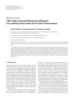
autocorrelation and cross-correlation values of MHPs are
shown in Figures 3 and 4,respectively.
However, Z
l,n
is the AWGN at the lth correlator output:
Z
l,n
=
N
s
−1
j=0
(j+1)T
f
jT
f
n(t)w
l
t − jT
f
− c
(1)
j
T
c
dt, (11)
and the corresponding variance, that is, noise power of
AWGN can be expressed as follows [13]:
σ
2
n
=
N
s
N
0
2
T
f
0
w
2
l
(x)dx =
N
s
N
0
2
. (12)
Theprobabilityofsymbolerrorratecanbewrittenasfrom
Appendix A:
P
r
=
1 −
N−1
l=0
1 − Q
SNR
. (13)
Sudhan Majhi et al. 5
×10
−9
10.50−0.5−1
Time (s)
1st & 2nd order Hermite
1st & 3rd order Hermite
2nd & 3rd order Hermite
−1
−0.8
−0.6
−0.4
−0.2
0
0.2
0.4
0.6
0.8
1
Amplitude
Crosscorrelation of Hermite pulses of order 1, 2 and 3
Figure 4: Crosscorrelation values of short duration MHPs of 1st-,
2nd-, and 3rd-order pulses.
4. PERFORMANCE IN MULTIPATH CHANNEL
The system performance of the orthogonal pulse-based
modulation scheme decreases in the presence of multi-
path channel. The RAKE fingers are used to collect the
strongest multiple components of a signal. Figure 5 shows
the RAKE receiver structure for multipath channel model.
The complexity of RAKE receiver scheme increases with the
number of strong multipath components. The performance
and robustness of a system in multipath environment is
often determined by the amount of multipath energy that
can be collected at the receiver. If there are N
u
users and
each experiences a different channel model, then the received
signal can be expressed as
r(t)
=
N
u
k=1
L
p
l=1
α
(k)
l
s
(k)
t − τ
(k)
l
+ n(t), (14)
where α
(k)
l
is the path gain and τ
(k)
l
is the time delay of lth
path for kth user, and n(t) is the AWGN. The reference signal
of user 1 at qth (
= 0, 1, , N −1) correlator can be expressed
as
φ
(1)
q
(t) =
N
s
−1
j=0
v
(1)
q
t − jT
f
− c
(1)
j
T
c
, (15)
where N
s
is the total number of time frame for a symbol and
v
(1)
q
(t) =
L
p
p=1
α
(1)
p
w
(1)
q
t − τ
(1)
p
. (16)
Since multiple pulses are transmitted in single-time
frame, the transmitted signal contain several pulses. How-
ever, template signal at each RAKE finger in the receiver
a
0
, a
1
, ··· , a
N−1
Tr an sm it te d
symbol
S/P
a
0
a
1
.
.
.
a
N−1
w
0
(t)
w
1
(t)
w
N−1
(t)
.
.
.
Tx
(a)
Rx
r(t)
a
0
, a
1
, ··· , a
N−1
Received
symbol
P/S
0th correlator
1st correlator
N
− 1th correlator
.
.
.
a
0
a
1
.
.
.
a
N−1
(b)
Channel estimator Weight estimator
r(t)
Path selection
w
q
(t − τ
1
)
w
q
(t − τ
2
)
.
.
.
w
q
(t − τ
Lp
)
dt
dt
.
.
.
dt
α
1
α
2
.
.
.
α
Lp
>
<
a
q
(c)
Figure 5: (a) A simple transmitter structure for N-bit OOK-PSM
scheme. (b) Receiver structure for combined N-bit OOK-PSM
scheme. (c) RAKE receiver structure for qth (q
= 0, 1, , N − 1)
correlator.
contains only one pulse. That is, the sum of several pulses
is correlated with single pulse waveform, which creates inter-
ferences in the presence of timing jitter and in asynchronous
systems. The pulses with short duration are not orthogonal
and they may overlap with one another. When a pulse
overlaps with itself, it is called interpulse interference (IPI) or
self-interference and when pulse interferes with other pulses,
it is called multipulse interference (MPI). The decision
statistics of user 1 in the qth correlator can be written as
Z
(1)
q
=
(j+1)T
f
jT
f
r(t)φ
(1)
q
(t)dt
= S
(1)
q
+IPI
(1)
q
+MPI
(1)
q
+MAI
(1)
q
+ N
(1)
q
,
(17)
where S
(1)
q
is the desired signal, IPI
(1)
q
is the IPI, MPI
(1)
q
is
the MPI, MAI
(1)
q
is the MAI due to presence of multiple
users, and N
(1)
q
is the AWGN term. The IPI, MPI, MAI, and
6 EURASIP Journal on Wireless Communications and Networking
AWGN terms behave like an interference noise mixed with
the original signal. The correct decision of Z
(1)
q
is possible
only if the desired signals, IPI, MPI, MAI, and AWGN are
known precisely. Therefore, these terms need to be analyzed.
4.1. Desired signal
For analysis, it is assumed that perfect synchronization exists
between transmitter and the reference receiver. Assuming
that τ
(1)
l
= 0 and the transmitted symbol uses qth-order
pulse, w
(1)
q
(t), the desired average signal S
(1)
q
, can be expressed
as [22, 23]
S
(1)
q
=
E
(1)
tr
N
s
−1
j=0
L
p
p=1
α
(1)
p
α
(1)
p
×
T
f
0
w
(1)
q
t − c
(1)
j
T
c
− τ
(1)
p
w
(1)
q
t − c
(1)
j
T
c
− τ
(1)
p
dt
=
E
(1)
tr
N
s
L
p
p=1
α
(1)
p
2
.
(18)
It is observed that the received energy in multipath channel
increases with the increase in the number of RAKE fingers.
This improves system performance at the cost of system
complexity. Therefore, a tradeoff between performance and
system complexity is required to design a reliable system for
multipath channel.
4.2. Interpulse interference (IPI)
IPI is related to interference with the same-order pulses and
depends on the number of multipath components in the
signal but is not concerned with the number of users in the
system. The average variance of IPI
(1)
q
can be written from
Appendix B as
σ
2
IPI
= E
(1)
tr
N
s
T
−1
f
L
p
p=1
L
p
l=1
L
p
p
=1
p
/
=p
L
p
l
=1
l
/
=l
α
(1)
p
α
(1)
l
α
(1)
p
α
(1)
l
X(Δ), (19)
where X(Δ)
= E{R
(1,1)
(τ
(1)
l
− τ
(1)
p
)R
(1,1)
(τ
(1)
l
− τ
(1)
p
)}.The
IPI degrades the system performance when systems are
not synchronized and improves for synchronized with
orthogonal pulses. Designing orthogonal pulses with short
duration is an important and challenging task for OOK-PSM
modulation scheme.
4.3. Multipulse interference (MPI)
MPI is related to interference with different-order pulses
and depends on the number of multipath components. It
does not depend on the number of users in the system. The
average variance of MPI
(1)
q
can be written from Appendix B
σ
2
MPI
=E
(1)
tr
N
s
T
−1
f
L
p
p=1
L
p
l=1
L
p
p
=1
p
/
=p
L
p
l
=1
l
/
=l
N
m=1
m
/
=q
N
m
=1
m
/
=q
α
(1)
p
α
(1)
l
α
(1)
p
α
(1)
l
Y(Δ),
(20)
MPI also degrades the system performance for higher cross-
correlation values of orthogonal pulses in both synchronized
and a synchronized systems. Since Y(
·) is the expectation
of product of R
(1,1)
qm
(·)andR
(1,1)
q
m
(·), R
(1,1)
qm
(·) is the cross-
correlation value of two different-order pulses q and m which
tends to zero. MPI tends to be zero for perfect orthogonal
pulses and synchronized systems irrespective of the number
of multipaths are present in the received signal.
4.4. Multiple-access interference
Under ideal conditions, the receiver is not affected by the
presence of multiple transmissions for perfectly orthogonal
TH-codes. In practice, however, systems do not achieve
ideal synchronization and codes lose orthogonality due
to different propagation delays from different paths. The
receiver might not be able to remove undesired signals
completely and as a consequence, system performance is
affected by MAI [2, 21, 24]. The average variance of MAI
(1)
q
can be written from Appendix B as
σ
2
MAI
=N
s
T
−1
f
N
u
k=2
N
u
k
=2
E
(k)
tr
E
(k
)
tr
L
p
p=1
L
p
l=1
L
p
p
=1
L
p
l
=1
α
(1)
p
α
(k)
l
α
(1)
p
α
(k)
l
V(Δ
),
(21)
where V(Δ
) = E{R
(1,k)
(Δ
1
)R
(1,k)
(Δ
2
)} and Δ
2
= (c
(1)
j
−
c
(k
)
j
)T
c
− (τ
(1)
p
− τ
(k
)
l
). In a single-user system, MAI is zero
and in a multiple-user system MAI is zero if TH-codes
are orthogonal and users are synchronized irrespective of
the pulse characteristic. However, designing synchronized
systems and using orthogonal TH-codes is a difficult task
for TH-UWB transceiver. Therefore, MAI can be reduced by
using orthogonal-based modulation schemes and assigning
different exclusive orthogonal subsets for different users.
4.5. Bit-error rates
Due to the different autocorrelation values for different
pulses, each correlator gives a different probability of error.
It can easily be proved that the noise/interference terms
are zero-mean Gaussian variables, and so the corresponding
probability of error of the lth correlator in the presence of
IPI, MPI, and MAI can be written as [20]
P
l
= Q
⎛
⎜
⎝
S
(1)
q
2
2
σ
2
IPI
+ σ
2
MPI
+ σ
2
MAI
+ σ
2
N
⎞
⎟
⎠
, (22)
Sudhan Majhi et al. 7
1614121086420
E
b
/N
0
(dB)
PSM
Bi-orthogonal
PPM-PSM
BPSK-PSM
OOK-PSM
Theory of OOK-PSM
10
−5
10
−4
10
−3
10
−2
10
−1
10
0
BER
Pb vs E
b
/N
0
for 2-bit scheme
Figure 6: Performance of PSM, BPSM, PPM-PSM, BPSK-PSM,
and OOK-PSM for 2-bit symbols transmission scheme for modified
Hermite pulses in AWGN.
where σ
2
N
is defined in Appendix B. Since each decision
is independent, the average probability of bit errors and
symbol errors can be obtained in similar way shown in
Appendix A.
5. SIMULATION RESULTS AND DISCUSSION
In this section, simulation results for 2-bit PSM and its
combined schemes are analyzed. The simulation studies are
conducted in AWGN and IEEE802.15.3a UWB multipath
channel under the assumption of perfect synchronization.
The present simulation studies assume a fixed-threshold
level. Since threshold value is insensitive to number of users,
a fixed-threshold value θ
th
= γ
E
tx
has been chosen rather
than selecting optimum threshold values adaptively, where
γ is normalized threshold value. For multipath channel, a
standard method based on [25] is used to obtain γ.The
present simulation studies use γ
= 0.5 for AWGN channel
and γ
= 0.75 for CM1 channel. All simulations studies
use MHPs and prolate spheroidal wave functions (PSWFs)
orthogonal pulses without using any coding or guard interval
[7, 11, 12].
5.1. AWGN component
The performance of 2-bit OOK-PSM scheme in AWGN
channel using MHPs and PSWFs is shown in Figures 6 and
7, respectively. It can be seen that all combined modulation
schemes out perform PSM scheme. Due to fewer pulses and
receiver correlators than those used in PSM, the proposed
scheme provides low complexity for system design. It does
not require a large number of orthogonal pulses and receiver
1614121086420
E
b
/N
0
(dB)
PSM
Bi-orthogonal
2PPM-PSM
BPSK-PSM
OOK-PSM
10
−5
10
−4
10
−3
10
−2
10
−1
10
0
BER
BER vs E
b
/N
0
for 2-bit scheme
Figure 7: Performance of PSM, BPSM, PPM-PSM, BPSK-PSM, and
OOK-PSM for 2-bit symbols transmission scheme for PSWF pulses
in AWGN.
correlators for higher-level modulation schemes. Since it
uses few orthogonal pulses for transmission, it creates
fewer spectral spikes resulting in better coexistence with
overlapping NB systems.
When compared with BPSM scheme, the proposed
scheme requires fewer pulses and receiver correlators for
similar data rates. For a 2-bit modulation scheme, OOK-
PSM shows nearly the same performance as that of BPSM.
Due to limited correlation properties of higher-order orthog-
onal pulses, the proposed scheme performs better than
BPSM-based system when the number of bits per symbol is
increased.
From Figures 6 and 7, it can be observed that BPSK-
PSM results in slightly better performance than that in OOK-
PSM scheme. Since the performance difference between
conventional BPSK and OOK is 3 dB in AWGN channel,
it is also expected that performance of BPSK-PSM should
give 3 dB over OOK-PSM scheme. As the number of bits
per symbol increases, the performance difference between
BPSK-PSM and OOK-PSM decreases. This is because of
the increased average number of pulses in the BPSK-
PSM modulation when compared with OOK-PSM. For
example, in 2-bit BPSK-PSM scheme, each symbol requires
two orthogonal pulses, whereas OOK-PSM requires one
pulse except for symbol 11 which requires two pulses. This
difference in number of average pulses is more visible when
the number of bits per symbol is increased. Though the
pulses are said to be orthogonal, they are not orthogonal in
the finite time interval, as shown in Figures 3 and 4 [7]. This
leads to degradation in the performance of BPSK-PSM when
the number of average pulses is more within the same time
interval.
8 EURASIP Journal on Wireless Communications and Networking
1614121086420
E
b
/N
0
(dB)
Number of users
= 10
Number of users
= 30
Number of users
= 60
10
−5
10
−4
10
−3
10
−2
10
−1
10
0
BER
BER vs E
b
/N
0
for 1-bit and 2-bit for different number of users
1-bit
scheme
2-bit
scheme
3-bit
scheme
Figure 8: Performance of 1-bit, 2-bit, and 3-bit symbols transmis-
sion of the OOK-PSM scheme for different numbers of users in
AWG N.
2520151050
E
b
/N
0
(dB)
PSM
Bi-orthogonal
2PPM-PSM
BPSK-PSM
OOK-PSM
10
−5
10
−4
10
−3
10
−2
10
−1
10
0
BER
BER vs E
b
/N
0
for 2-bit scheme in multipath −10 dB
Figure 9: Performance of various modulation schemes for 2-bit
symbols transmission in a multipath environments. The receiver
assumes a RAKE-combination by considering all paths within
−10 dB of the strongest path. The schemes uses orthogonal pulses
based on MHPs.
It can be seen that the proposed scheme results in
nearly the same performance as that of 2PPM-PSM scheme.
However, due to presence of nonorthogonal pulse position
in 2PPM-PSM scheme, ISI and MAI issues resurface in
2PPM-PSM modulation scheme which can severely affect
system performance in multipath environments. Maintain-
ing orthogonality of the constellation vector is important for
better system performance. So, it requires coded modulation
and memory in the receiver to achieve the orthogonality
of constellation vector [12, 26]. Since 2PPM-PSM scheme
uses pulse positions, amplitudes, and orthogonal pulses,
recovering of signals at the receiver is complicated in the
presence of multipath. In addition, the complexity of system
design for 2PPM-PSM is increased by the presence of
constellation matrix, map-decision vector, and distance-
comparator vector in the receiver [27].
In Figure 8, the performance in multiple user environ-
ment is presented in AWGN channel. It can be seen that
performance decreases with increase in the number of bits
per symbol. This is largely because of the increase in the
number of orthogonal pulses used for signal transmission.
Since pulses are not strictly orthogonal within the finite
interval, interference among these pulses leads to perfor-
mance degradation. However, across multiple users, the
performance degradation is minimal. On the other hand,
due to presence of a single pulse in 1-bit transmission, the
performance difference with respect to users is more visible;
but in 2-bit and 3-bit schemes, performance difference with
respect to number of users is less visible. This is because
these schemes use multiple orthogonal pulses which reduce
cross-correlation terms in MAI in synchronized systems. The
simulation results justify the lower MAI compared to single-
pulse systems as shown in (10).
5.2. Multipath channel model
Since orthogonal pulses are sensitive to multipath channel, it
is required to analyze the performance of PSM modulation
and its combined scheme in the presence of multipath.
Channel estimation is done by using selective RAKE receiver
and maximum ratio combining (MRC). The number of
significant paths is decided by taking all paths within 10 dB
of the strongest path. To collect all these multipaths, a
RAKE-combining method is employed at the receiver. It is
assumed that the transmitted pulse average interval is much
longer than the pulse duration. In channel estimation, only
distinguishable paths are selected.
Figures 9 and 10 show the performance of combined
PSM schemes by using MHPs and PSWFs, respectively,
where the number of RAKE fingers is 17. The PSWFs give
better performance than MHPs in the presence of multipath.
From the figures, it can be seen that the proposed OOK-PSM
shows better performance than the PSM scheme, but BPSK-
PSM gives better performance than all the other modulation
schemes. Since zero is represented by pulse off,OOKcom-
plexity is nearly half of that in any other modulation scheme.
Therefore, M-ary OOK-PSM compensates lesser system
performance with lower complexity design. Although other
modulation schemes give nearly the same performance, due
to simplicity of OOK scheme, its combined form with PSM
is an appropriate choice for system design with low cost.
6. CONCLUSION
This paper discusses a combined modulation scheme for N-
bit symbol transmission by using fewer orthogonal pulses
Sudhan Majhi et al. 9
2520151050
E
b
/N
0
(dB)
PSM
Bi-orthogonal
2PPM-PSM
BPSK-PSM
OOK-PSM
10
−5
10
−4
10
−3
10
−2
10
−1
10
0
BER
BER vs E
b
/N
0
for 2-bit scheme in multipath −10 dB
Figure 10: Performance of various modulation schemes for 2-bit
symbols transmission in a multipath environments. The receiver
assumes a RAKE-combination by considering all paths within
−10 dB of the strongest path. The schemes uses orthogonal pulses
based on PSWFs.
and receiver correlators than those used in conventional PSM
and biorthogonal PSM schemes. Using OOK modulation,
the proposed scheme reduces system complexity and needs
minimum average transmitted power, which is critical for
low-cost and energy-constrained UWB systems. The orthog-
onal pulses reduce MAI in the presence of multiple users, and
give better system performance in AWGN environment than
conventional single-pulse systems. This paper also shows the
performance of PSM and its combined schemes in multipath
channel model. The proposed scheme can be used for low-
complexity, energy-constrained, and multiple-access UWB
communication systems without degrading the data rate of
existing combined schemes.
APPENDICES
A. AWGN ENVIRONMENTS
Due to different autocorrelation values for different orders
of pulses, each correlator gives different probability of error.
By using (7), (10), and (12), probability of error of the lth
correlator in the presence of MAI can be written as
P
l
=Q
⎛
⎜
⎝
E
(1)
b
2
σ
2
n
+σ
2
l,Mai
⎞
⎟
⎠
=
Q
⎛
⎝
N
2
s
E
rx
2
σ
2
n
+σ
2
l,Mai
⎞
⎠
=
Q
SNR
,
(A.1)
where
SNR
=
E
b
2
N
0
+2R
b
E
b
N
u
k=2
T
M
0
R
(k)
n,l
(τ)
2
dτ
,(A.2)
and R
b
= 1/N
s
T
f
is the data rate and E
b
= N
s
E
rx
is
the received energy at the receiver. Since each decision is
independent, the average probability of bit error is
Pr
b
=
1
N
N−1
l=0
P
l
,(A.3)
where N is the total number of correlators for N-bit symbols
transmission. The correct decision of the lth correlator is
1
− P
l
. The received symbol is perfect if all correlators
make correct decisions. Since decisions are independent, the
probability of correct decision for a symbol can be defined as
P
c
=
N−1
l=0
1 − P
l
. (A.4)
The probability of symbol error rate can be calculated
by using (A.1). The probability of symbol error rate can be
expressed as
P
r
=
1 − P
c
=
1−
N−1
l=0
1−P
l
=
1−
N−1
l=0
1−Q
SNR
.
(A.5)
B. MULTIPATH ENVIRONMENTS
B.1. Interpulse interference
The term IPI
(1)
q
of user 1 in the qth correlator can be
expressed from (17)as
IPI
(1)
q
=
E
(1)
tr
N
s
−1
j=0
L
p
p=1
L
p
l=1
l
/
=p
α
(1)
p
α
(1)
l
×
T
f
0
w
(1)
q
t−c
(1)
j
T
c
−τ
(1)
l
w
(1)
q
t−c
(1)
j
T
c
−τ
(1)
p
dt
=
E
(1)
tr
N
s
L
p
p=1
L
p
l=1
l
/
= p
α
(1)
p
α
(1)
l
R
(1,1)
τ
(1)
l
− τ
(1)
p
,
(B.1)
where R
(k,k)
(τ
(1)
l
−τ
(1)
p
) =
T
f
0
w
(k)
q
(t)w
(k)
q
(t−τ
(1)
l
−τ
(1)
p
)dt and
q
∈{0, 1, , N −1}. The corresponding average variance of
10 EURASIP Journal on Wireless Communications and Networking
IPI
(1)
q
for the N
s
T
f
time frames is σ
2
IPI
and can be expressed as
σ
2
IPI
=
E
IPI
(1)
q
2
−
E
IPI
(1)
q
2
N
s
T
f
= E
(1)
tr
N
s
T
−1
f
E
⎧
⎪
⎪
⎪
⎨
⎪
⎪
⎪
⎩
⎛
⎜
⎜
⎜
⎝
L
p
p=1
L
p
l=1
l
/
=p
α
(1)
p
α
(1)
l
× R
(1,1)
τ
(1)
l
− τ
(1)
p
⎞
⎟
⎟
⎟
⎠
2
⎫
⎪
⎪
⎪
⎬
⎪
⎪
⎪
⎭
=
E
(1)
tr
N
s
T
−1
f
L
p
p=1
L
p
l=1
L
p
p
=1
p
/
=p
L
p
l
=1
l
/
=l
α
(1)
p
α
(1)
l
α
(1)
p
α
(1)
l
X(Δ),
(B.2)
where X(Δ)
= E{R
(1,1)
(τ
(1)
l
− τ
(1)
p
)R
(1,1)
(τ
(1)
l
− τ
(1)
p
)}.
B.2. Multipulse interference
The term MPI
(1)
q
ofuser1intheqth correlator can be written
from (17)as
MPI
(1)
q
=
E
(1)
tr
N
s
−1
j=0
L
p
p=1
L
p
l=1
l
/
=p
N
m=1
m
/
=q
α
(1)
p
α
(1)
l
×
T
f
0
w
(1)
q
t−c
(1)
j
T
c
−τ
(1)
l
w
(1)
q
t−c
(1)
j
T
c
−τ
(1)
p
dt
=
E
(1)
tr
N
s
L
p
p=1
L
p
l=1
l
/
= p
N
m=1
m
/
= q
α
(1)
p
α
(1)
l
R
(1,1)
qm
τ
(1)
l
− τ
(1)
p
.
(B.3)
The average variance of σ
2
MPI
can be expressed as similar way
of (B.2)
σ
2
MPI
=E
(1)
tr
N
s
T
−1
f
L
p
p=1
L
p
l=1
L
p
p
=1
p
/
=p
L
p
l
=1
l
/
=l
N
m=1
m
/
=q
N
m
=1
m
/
=q
α
(1)
p
α
(1)
l
α
(1)
p
α
(1)
l
Y(Δ),
(B.4)
where Y(Δ)
= E{R
(1,1)
qm
(τ
(1)
l
− τ
(1)
p
)R
(1,1)
q
m
(τ
(1)
l
− τ
(1)
p
)}.
B.3. Multiaccess interference
The term MAI
(1)
q
of OOK-PSM schemes for the N
u
users can
be written from (17)as
MAI
(1)
q
=
N
u
k=2
E
(k)
tr
N
s
−1
j=0
L
p
p=1
L
p
l=1
α
(k)
l
α
(1)
p
×
T
f
0
w
(k)
q
t−c
(k)
j
T
c
−τ
(k)
l
w
(1)
q
t−c
(1)
j
T
c
−τ
(1)
p
dt
= N
s
N
u
k=2
E
(k)
tr
L
p
p=1
L
p
l=1
α
(k)
l
α
(1)
p
R
(1,k)
Δ
,
(B.5)
where Δ
1
= (c
(1)
j
− c
(k)
j
)T
c
− (τ
(1)
p
− τ
(k)
l
).
The variance of σ
2
MAI
over the N
s
T
f
time frames can be
expressed as similar way of (B.2)
σ
2
MAI
= N
s
T
−1
f
N
u
k=2
N
u
k
=2
E
(k)
tr
E
(k
)
tr
×
L
p
p=1
L
p
l=1
L
p
p
=1
L
p
l
=1
α
(1)
p
α
(k)
l
α
(1)
p
α
(k
)
l
V
Δ
,
(B.6)
where V(Δ
) = E{R
(1,k)
(Δ
1
)R
(1,k
)
(Δ
2
)},andΔ
2
= (c
(1)
j
−
c
(k
)
j
)T
c
− (τ
(1)
p
− τ
(k
)
l
).
B.4. AWGN noise in multipath
N
(1)
q
is the AWGN generated by qth correlator and can be
expressed from (17)as
N
(1)
q
=
N
s
−1
j=0
L
p
p=1
α
(1)
p
T
f
0
n(t)w
(1)
q
t − c
(1)
j
T
c
− τ
(1)
p
dt. (B.7)
The corresponding noise is
σ
2
N
=
E
N
(1)
q
2
−
E
N
(1)
q
2
N
s
T
f
= N
s
L
p
p=1
α
(1)
p
2
E
T
f
0
n(t)n(t)dt
=
N
0
N
s
L
p
p=1
α
(1)
p
2
2
.
(B.8)
REFERENCES
[1] S. Majhi, A. S. Madhukumar, and A. B. Premkumar, “Reduc-
tion of UWB interference at NB systems based on a generalized
pulse waveform,” IEICE Electronics Express, vol. 3, no. 14, pp.
361–367, 2006.
[2] G. Durisi, J. Romme, and S. Benedetto, “A general method
for SER computation of M-PAM and M-PPM UWB systems
for indoor multiuser communications,” in Proceedings of IEEE
Global Telecommunications Conference (GLOBECOM ’03), vol.
2, pp. 734–738, San Francisco, Calif, USA, December 2003.
[3] L. Bin, E. Gunawan, and L. C. Look, “On the BER performance
of TH-PPM UWB using Parr’s monocycle in the AWGN
channel,” in Proceedings of IEEE Conference on Ultra Wideband
Systems and Technologies, pp. 403–407, Reston, Va, USA,
November 2003.
[4] J. Foerster, “UWB channel modeling sub-committee report
final,” IEEEP802.15 Working Group for Wireless Personal
Area Networks (WPANs), February 2003.
[5] M.Z.WinandR.A.Scholtz,“Ontheenergycaptureofultraw-
ide bandwidth signals in dense multipath environments,” IEEE
Communications Letters, vol. 2, no. 9, pp. 245–247, 1998.
[6] I. Guvenc and H. Arslan, “On the modulation options for
UWB systems,” in Proceedings of IEEE Military Commu-
nications Conference (MILCOM ’03), vol. 2, pp. 892–897,
Monterey, Calif, USA, October 2003.
[7] M.Ghavami,L.B.Michael,S.Haruyama,andR.Kohno,“A
novel UWB pulse shape modulation system,” Wireless Personal
Communications, vol. 23, no. 1, pp. 105–120, 2002.
Sudhan Majhi et al. 11
[8] G.T.F.deAbreu,C.J.Mitchell,andR.Kohno,“Onthedesign
of orthogonal pulse-shape modulation for UWB systems using
Hermite pulses,” Journal of Communications and Networks,
vol. 5, no. 4, pp. 328–343, 2003.
[9] X. Chu and R. D. Murch, “Multidimensional modulation
for ultra-wideband multiple-access impulse radio in wireless
multipath channels,” IEEE Transactions on Wireless Communi-
cations, vol. 4, no. 5, pp. 2373–2386, 2005.
[10] S. Gezici, Z. Sahinoglu, H. Kobayashi, and H. V. Poor, “Ultra-
wideband impulse radio systems with multiple pulse types,”
IEEE Journal on Selected Areas in Communications, vol. 24, no.
4, pp. 892–898, 2006.
[11] K. Usuda, H. Zhang, and M. Nakagawa, “M-ary pulse shape
modulation for PSWF-based UWB systems in multipath
fading environment,” in Proceedings of IEEE Global Telecom-
munications Conference (GLOBECOM ’04), vol. 6, pp. 3498–
3504, Dallas, Tex, USA, November-December 2004.
[12] C. J. Mitchell, G. T. F. de Abreu, and R. Kohno, “Combined
pulse shape and pulse position modulation for high data rate
transmissions in ultra-wideband communications,” Interna-
tional Journal of Wireless Information Networks, vol. 10, no. 4,
pp. 167–178, 2003.
[13] W. Hu and G. Zheng, “Orthogonal Hermite pulses used
for UWB M-ary communication,” in Proceedings of the
International Conference on Information Technology: Coding
and Computing (ITCC ’05), vol. 1, pp. 97–101, Las Vegas, Nev,
USA, April 2005.
[14] S. Majhi, A. S. Madhukumar, and A. B. Premkumar, “Perfor-
mance of orthogonal based modulation schemes for TH-UWB
communication systems,” IEICE Electronics Express, vol. 4, no.
8, pp. 238–244, 2007.
[15] F. Nekoogar, Ultra-Wideband Communication, Prentice Hall,
Upper Saddle River, NJ, USA, 2005.
[16] S. Majhi, A. S. Madhukumar, A. B. Premkumar, and F.
Chin, “M-ary signaling for ultra wideband communication
systems based on pulse position and orthogonal pulse shape
modulation,” in Proccedings of IEEE Wireless Communications
and Networking Conference (WCNC ’07), pp. 2795–2799,
Kowloon, Hong Kong, March 2007.
[17] K. Siwiak and D. McKeown, Ultra-Wideband Radio Technol-
ogy, John Wiley & Sons, New York, NY, USA, 2004.
[18] A. S. Madhukumar, Z. Ye, and S. Majhi, “Coexisting narrow-
band and ultra wideband systems: analysis of power spectral
density and in-band interference power,” WSEAS Transactions
on Communications, vol. 6, no. 2, pp. 318–324, 2007.
[19] M. Z. Win, “Spectral density of random time-hopping
spread-spectrum UWB signals with uniform timing jitter,”
in Proceedings of IEEE Military Communications Conference
(MILCOM ’99), vol. 2, pp. 1196–1200, Atlantic City, NJ, USA,
October-November 1999.
[20] I. Guvenc and H. Arslan, “Performance evaluation of UWB
systems in the presence of timing jitter,” in Proceedings of IEEE
Conference on Ultra Wideband Systems and Technologies,pp.
136–141, Reston, Va, USA, Novemebr 2003.
[21] B. Hu and N. C. Beaulieu, “Precise bit error rate of TH-PPM
UWB systems in the presence of multiple access interference,”
in Proceedings of IEEE Conference on Ultra Wideband Systems
and Technologies, pp. 106–110, Reston, Va, USA, November
2003.
[22] T. Jia and D. I. Kim, “Analysis of average signal-to-
interference-noise ratio for indoor UWB rake receiving sys-
tem,” in Proceedings of the 61st IEEE Vehicular Technology
Conference (VTC ’05), vol. 2, pp. 1396–1400, Stockholm,
Sweden, May-June 2005.
[23] L. Jiang, Y. Wang, and J. Guo, “The capacity of M-ary PPM
ultra-wideband communication over multipath channels,” in
Proceedings of IEEE International Symposium on Microwave,
Antenna, Propagation and EMC Technology for Wireless Com-
munication (MAPE ’05), vol. 2, pp. 1606–1609, Beijing, China,
August 2005.
[24] M. G. D. Benedetto and G. Giancola, Understanding Ultra
Wideband Radio Fundamentals, Prentice Hall, Upper Saddle
River, NJ, USA, 2004.
[25] K H. Kim, S. Choi, Y. Park, et al., “Enhanced noncoherent
OOK UWB PHY and MAC for positioning and ranging,” IEEE
P802.15 Working Group for Wireless Personal Area Networks
(WPANs), January 2005.
[26] T. Matsumoto, H. Ochiai, and R. Kohno, “Super-orthogonal
convolutional coding with orthogonal pulse waveform for
ultra wideband communications,” in Proceedings of the Inter-
national Workshop on Ultra Wideband Systems; Joint with
Conference on Ultra Wideband Systems and Technologies,pp.
202–206, Kyoto, Japan, May 2004.
[27] K. Eshima, Y. Hase, S. Oomori, F. Takahashi, and R. Kohno,
“M-ary UWB system using Walsh codes,” in Proceedings of
IEEE Conference on Ultra Wideband Systems and Technologies
(UWBST ’02), pp. 37–40, Baltimore, Md, USA, May 2002.