Báo cáo hóa học: " Research Article An Efficient Watermarking Technique for the Protection of Fingerprint Image" doc
Bạn đang xem bản rút gọn của tài liệu. Xem và tải ngay bản đầy đủ của tài liệu tại đây (3.15 MB, 20 trang )
Hindawi Publishing Corporation
EURASIP Journal on Information Security
Volume 2008, Article ID 918601, 20 pages
doi:10.1155/2008/918601
Research Article
An Efficient Watermarking Technique for the Protection of
Fingerprint Images
K. Zebbiche,
1
F. Khelifi,
2
and A. Bouridane
1
1
School of Electronics, Electrical Engineering, and Computer Science, Quee n’s University of Belfast, Belfast BT7 1NN,
Northern Ireland, UK
2
Department of Electronic Imaging and Media Communications (EIMC), School of Informatics, University of Bradford,
Richmond Road, Bradford, West Yorkshire, BD7 1DP, UK
CorrespondenceshouldbeaddressedtoK.Zebbiche,
Received 12 February 2008; Revised 7 July 2008; Accepted 11 September 2008
Recommended by D. Kirovski
This paper describes an efficient watermarking technique for use to protect fingerprint images. The rationale is to embed
the watermarks into the ridges area of the fingerprint images so that the technique is inherently robust, yields imperceptible
watermarks, and resists well against cropping and/or segmentation attacks. The proposed technique improves the performance
of optimum multibit watermark decoding, based on the maximum likelihood scheme and the statistical properties of the host
data. The technique has been applied successfully on the well-known transform domains: discrete cosine transform (DCT)
and discrete wavelet transform (DWT). The statistical properties of the coefficients from the two transforms are modeled by a
generalized Gaussian model, widely adopted in the literature. The results obtained are very attractive and clearly show significant
improvements when compared to the conventional technique, which operates on the whole image. Also, the results suggest that the
segmentation (cropping) attack does not affect the performance of the proposed technique, which also provides more robustness
against other common attacks.
Copyright © 2008 K. Zebbiche et al. This is an open access article distributed under the Creative Commons Attribution License,
which permits unrestricted use, distribution, and reproduction in any medium, provided the original work is properly cited.
1. INTRODUCTION
Biometric-based authentication systems that use physio-
logical characteristics (fingerprint, face, iris, etc.) and/or
behavioral traits (signature, voice, etc.) of persons are gaining
more and more interest in the last years since they are
based on information that is permanently associated with
a person. Among various commercially available biometric-
based systems, fingerprint-based techniques are the most
mature, extensively studied, and widely deployed. While
biometric-based techniques have inherent advantages over
other authentication techniques such as token-based or
knowledge-based techniques, ensuring the security and
integrity of data is a paramount issue. Recently, water-
marking techniques have been introduced and shown to
be promising for protecting fingerprint data and increasing
the security level of fingerprint-based systems [1–5]. For
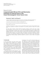
example, watermarking of fingerprint images can be used to
secure central databases from which fingerprint images are
transmitted on request to intelligence agencies in order to
use them for identification and classification purposes (see
Figure 1).
Depending on the embedding domain, existing algo-
rithms for image watermarking usually operate either in
the spatial domain [6, 7] or in a transform domain such
as the discrete cosine transform (DCT) [8, 9] and the
discrete wavelet transform (DWT) [10, 11]. However, most
research works have been proposed in the transform domain
because of its energy compaction property which suggests
that the distortions introduced by the watermarks into the
transform coefficients will spread over all the pixels in the
spatial domain so as the changes introduced in these pixels
values are visually less significant. Also, depending on the
embedding rule used, the watermarks are often embedded
using either an additive or a multiplicative rule. Additive rule
has been broadly used in the literature due to its simplicity
[8, 9, 12]. On the other hand, multiplicative rule is more
efficient because it is image dependent and exploits the
characteristics of the human visual system (HVS) in a better
way [13–16].
2 EURASIP Journal on Information Security
Fingerprint
image
Wate rmark
encoder
Channel
Wate rmark
decoder
Extracted
ID
Ve rification
Image
rejected
No
Ye s
Fingerprint-based
identification system
ID
Figure 1: Block diagram of a watermarking application for fingerprint images.
(a:1) (a:2) (a:3)
(b:1) (b:2) (b:3)
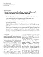
Figure 2: Test images with different ridges area size from DB1:
(a,b:1)originalimages(a:Image98
2, b: Image 20 1), (a, b: 2)
segmentation masks, (a, b: 3) watermarking masks.
Researchers in watermarking domain have focused their
works on two fundamental issues: watermark detection
and watermark decoding (extraction). In the latter, usually
referred to as multibit watermarking, a full decoding is
carried out to extract the hidden message, which can be an
ownership identifiers, transaction dates, a serial numbers,
and so forth. Such a watermarking can be found in finger-
printing, steganography, and the protection of intellectual
property rights. In multibit watermarking, errors may occur
when extracting the hidden message. Error probability can be
used as a measure of the watermarking system performance.
In the literature, optimum decoders have been proposed
and are based on a statistical modeling of the host data.
Hernandez et al. propose a structure of optimum decoder for
additive watermarks embedded within the DCT coefficients,
modeled by a generalized Gaussian distribution (GGD). The
problem of optimum decoding for multiplicative multibit
watermarking has been addressed in [17–19]. In [17], the
authors propose a new optimum decoder of watermarks
embedded in the DFT coefficients modeled using a Weibull
distribution, while Song in [18] proposes a general statistical
procedure based on the total efficient score vector for both
GGD and Weibull distribution. In [19],anewoptimum
decoder based on GGD has been proposed for extracting
watermarks embedded within DWT coefficients.
(a:1) (a:2) (a:3)
(b:1) (b:2) (b:3)
Figure 3: Test images with different ridges area size from DB2:
(a,b:1)originalimages(a:Image71
4, b: Image 75 7), (a, b: 2)
segmentation masks, (a, b: 3) watermarking masks.
(a:1) (a:2) (a:3)
(b:1) (b:2) (b:3)
Figure 4: Test images with ridges area size from DB3: (a, b:
1) original images (a: Image 47
3, b: Image 73 7), (a, b: 2)
segmentation masks, (a, b: 3) watermarking masks.
K. Zebbiche et al. 3
30025020015010050
Number of coefficients per information bit
10
−4
10
−3
10
−2
10
−1
10
0
BER
BER for image 98 2
(a)
25020015010050
Number of coefficients per information bit
10
−4
10
−3
10
−2
10
−1
10
0
BER
BER for image 20 1
(b)
55050045040035030025020015010050
Number of coefficients per information bit
10
−3
10
−2
10
−1
10
0
BER
BER for image 71 4
(c)
45040035030025020015010050
Number of coefficients per information bit
10
−4
10
−3
10
−2
10
−1
10
0
BER
BER for image 75 7
(d)
1000900800700600500400300200100
Number of coefficients per information bit
10
−2
10
−1
10
0
BER
BER for image 47 3
Proposed technique
Conventional technique
(e)
50045040035030025020015010050
Number of coefficients per information bit
10
−3
10
−2
10
−1
10
0
BER
BER for image 73 7
Proposed technique
Conventional technique
(f)
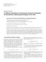
Figure 5:BERasafunctionofthenumberofcoefficients per bit for the test images. Watermark applied in the DCT domain.
In this work, the main contribution consists of embed-
ding the watermark within the foreground or the ridges area
by avoiding to embed it in the background area. This is
motivated by the following facts.
(i) Embedding watermarks into the ridges area increases
its robustness because an attacker is interested in
that area only (i.e., segmentation or cropping attack
is usually performed to extract the ridges area
from the background). Consequently, a part/portion
of the watermark which is embedded within the
background area can be removed, thus affecting
the robustness of the watermark. Furthermore, to
remove a watermark embedded in the ridges area,
an attacker needs to apply strong attacks (such as
additive noise and filtering) on that area, resulting in
severe degradations of the quality of the image, thus,
making it useless.
4 EURASIP Journal on Information Security
30025020015010050
Number of coefficients per information bit
10
−4
10
−3
10
−2
10
−1
10
0
BER
BER for image 98 2
(a)
30025020015010050
Number of coefficients per information bit
10
−3
10
−2
10
−1
10
0
BER
BER for image 20 1
(b)
1000900800700600500400300200100
Number of coefficients per information bit
10
−3
10
−2
10
−1
10
0
BER
BER for image 71 4
(c)
1000900800700600500400300200100
Number of coefficients per information bit
10
−3
10
−2
10
−1
10
0
BER
BER for image 75 7
(d)
1000900800700600500400300200100
Number of coefficients per information bit
10
−2
10
−1
10
0
BER
BER for image 47 3
Proposed technique
Conventional technique
(e)
1000900800700600500400300200100
Number of coefficients per information bit
10
−2
10
−1
10
0
BER
BER for image 73 7
Proposed technique
Conventional technique
(f)
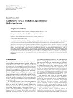
Figure 6: BER as a function of the number of coefficients per bit for the test images. Watermark applied in the DWT domain.
(ii) The human eye is less sensitive to noise and changes
in the texture regions; this makes sense to select the
ridges area for watermark embedding and ensures
imperceptibility of the embedded watermarks.
The proposed technique starts by first extracting the ridges
area using the segmentation technique proposed by Wu
et al. [20], which has been modified to generate adap-
tive thresholds instead of fixed ones. The output of the
segmentation results in a binary mask called segmentation
mask. This mask is then partitioned into nonoverlapping
blocks, where only the blocks belonging to the ridges
area are used to carry the watermark. This is represented
by another binary mask called watermarking mask.The
proposed technique has been introduced to increase the
performance of the optimum watermark decoder, whose
structure is theoretically based on a maximum-likelihood
K. Zebbiche et al. 5
600550500450400350300250200
Number of hidden information bits
10
−4
10
−3
10
−2
10
−1
10
0
BER
BER for image 98 2
(a)
200180160140120100
Number of hidden information bits
10
−3
10
−2
10
−1
10
0
BER
BER for image 20 1
(b)
500450400350300250200150100
Number of hidden information bits
10
−3
10
−2
10
−1
10
0
BER
BER for image 71 4
(c)
400350300250200150100
Number of hidden information bits
10
−3
10
−2
10
−1
BER
BER for image 75 7
(d)
600500400300200100
Number of hidden information bits
10
−2
10
−1
10
0
BER
BER for image 47 3
Proposed technique
Conventional technique
(e)
45035025015050
Number of hidden information bits
10
−3
10
−2
10
−1
10
0
BER
BER for image 73 7
Proposed technique
Conventional technique
(f)
Figure 7: BER as function of total amount of hidden information bits. Watermark applied in the DCT domain.
(ML) estimation scheme. For the sake of illustration, the
process of watermarking is applied in both the DCT and
the DWT domains, where the transform coefficients in each
domain are statistically modeled using a GGD that has been
shown, in the literature, to be the most accurate statistical
model. The results obtained in this work clearly demonstrate
the performance improvements achieved by the proposed
technique. Also, the segmentation process, which can be
thought of as an attack for fingerprint images, is shown
to have no influence on the overall performance of the
optimum decoder.
The paper is organized as follows. Section 2 describes
the technique used to extract the region of interest. A brief
description of watermark generation and the embedding
process for both the DCT and the DWT domains is given
in Section 3. Then, in Section 4, the multibit watermark
decoding (extraction) issue is addressed. The influence of
attacks on the overall performance of the optimum decoder
6 EURASIP Journal on Information Security
600550500450400350300250
Number of hidden information bits
10
−3
10
−2
10
−1
10
0
BER
BER for image 98 2
(a)
200180160140120100
Number of hidden information bits
10
−3
10
−2
10
−1
10
0
BER
BER for image 20 1
(b)
500450400350300250200150100
Number of hidden information bits
10
−2
10
−1
10
0
BER
BER for image 71 4
(c)
450400350300250200150100
Number of hidden information bits
10
−2
10
−1
10
0
BER
BER for image 75 7
(d)
600500400300200100
Number of hidden information bits
10
−2
10
−1
10
0
BER
BER for image 47 3
Proposed technique
Conventional technique
(e)
55045035025015050
Number of hidden information bits
10
−2
10
−1
10
0
BER
BER for image 73 7
Proposed technique
Conventional technique
(f)
Figure 8: BER as a function of total amount of hidden information bits. Watermark applied in the DWT domain.
is assessed through experimentation whose results and
analysis are reported in Section 5. Finally, conclusions are
drawn in Section 6.
2. RIDGES AREA DETECTION AND EXTRACTION
A captured fingerprint image usually consists of two areas:
the foreground and the background. The foreground or
ridges area is the component that originates from the
contact of a fingertip with the sensor. The noisy area at
the borders of the image is called the background area. An
extraction of the ridges area can be carried out by using a
segmentation technique whose objective is to decide whether
a part of the fingerprint image belongs to the foreground
(which is of our interest) or belongs to the background.
Several methods and techniques have been proposed in
the literature for segmenting fingerprint images [21, 22].
However, in our case, the technique must be robust to
common watermarking attacks in the sense that it also
detects the same ridges area even if a fingerprint image is
K. Zebbiche et al. 7
subjected to attacks such as compression, filtering, noise
addition. Unfortunately, most of these techniques are not
robust enough to resist image manipulations. In this work,
we propose to use Harris corner point features to segment
the fingerprint images. A Harris corner detector is based on
a local autocorrelation function of a signal to measure the
local changes of the signal with patches shifted by a small
amount in different directions [23]. It has been found in [20]
that the strength of a Harris point in the foreground area
is much higher than that in the background area. However,
the authors proposed to use different thresholds, which
are determined experimentally for each image. Also, they
noticed that some noisy regions are likely to have a higher
strength which cannot be eliminated even by using high
threshold value and proposed to use a heuristic algorithm
based on the corresponding Gabor response. In our case, we
found that an adaptive threshold can be obtained by using
Otsu thresholding method [24] which provides an excellent
threshold for fingerprint images from different databases.
When some morphological methods are applied to eliminate
the noisy regions, excellent segmented images are obtained.
The output of the segmentation process yields a seg-
mented image and/or a segmentation mask. Since Harris
point features method is a pointwise method, the segmen-
tation mask is a binary mask (i.e., 1 if the pixel is assigned to
the foreground area and 0 otherwise) of the same size as the
original image.
Once the ridges area is extracted, one has to ensure
that the watermark will be embedded within this extracted
area. We propose to divide the segmentation mask into
nonoverlapping blocks, where each block is classified as ridge
block or background block according to the number of
foreground pixels belonging to the block at hand (in this
paper, a block is considered to be a ridge block if and only
if all the block’s pixels are classified as a ridge pixel). Finally,
a binary watermarking mask is produced with a value of
1 if the block belongs to the ridges area and 0 otherwise.
Let I[n]
= I[n
1
, n
2
], 0 ≤ n
1
<N
1
,0 ≤ n
2
<N
2
be
a two-dimensional (2D) data representing the luminance
component of the image with size N
1
×N
2
pixels and SM[n]
be 2D binary matrix representing the segmentation mask
with N
1
×N
2
components. SM[n] is partitioned into n
b1
×n
b2
nonoverlapping blocks B
ij
,0≤ i<n
b1
,0 ≤ j<n
b2
,of
m
× m pixels, where n
b1
=N
1
/m and n
b2
=N
2
/m.Let
WM
ij
, where 0 ≤ i<n
b1
and 0 ≤ j<n
b2
be 2D binary
sequence representing the watermarking mask. Then, WM
ij
is obtained as follows:
WM
ij
=
+1, if B
ij
belongs to the ridges area;
0, otherwise.
(1)
To verify whether the segmentation technique extracts the
ridges area accurately, we have assessed this technique using
real fingerprint images from the FVC2004 databases (DB1,
DB2, and DB3) [25].Theimagespropertiesforallselected
databases are shown in Tab le 1 . For the sake of illustration,
only the results obtained on two fingerprint images (Figures
2, 3,and4) from each database are reported because similar
performances have been achieved while considering other
Table 1: Technologies used for the collection of FVC2004 databases.
Database Sensor type Image size Resolution (dpi)
DB1 Optical sensor 640 × 480 500
DB2 Optical sensor 328
× 364 500
DB3 Thermal sweeping sensor 300
× 480 500
images. The choice has been done on the basis of the
variability of the ridges area size.
Since the watermarks are inserted in the 8
× 8DCT
blocks, the size of a block is chosen to be a multiple
of 8. The experiments carried out have indicated that m
must be above 32 (m
≥ 32) to provide the same mask
even in the presence of attacks. Furthermore, extensive
experiments were carried out to determine the limitations
of each database in the presence of attacks such as wavelet
scalar quantization (WSQ) compression [26], additive white
Gaussian noise (AWGN), and mean filtering. These results
are necessary since the computed watermarking mask (i.e.,
the selected blocks) will be used to carry the watermark. The
first column of Tab le 2 reports the highest compression ratio
(in bits per pixel) below which the technique was able to
provide the same watermarking mask. The second column
of Ta bl e 2 shows the results obtained for an AWGN attack.
In the case of the mean filtering, the results are shown in the
third column of Ta bl e 2 . For each database, the mean peak
signal-to-noise ratio (PSNR) values are also shown for each
type of attack in order to assess the distortions introduced.
As can be seen from Ta b le 2 , all test images that form
the three databases are robust to mean filtering attack and
the technique can extract the same watermarking mask even
for a filtering attack with a window size of 7
× 7. However,
the test images from database DB2 are more sensitive to
WSQ compression and AWGN attacks than the images from
the other databases. Images from DB1 are very robust to
WSQ compression and images from DB3 are less sensitive
to AWGN.
3. WATERMARK GENERATION AND EMBEDDING
As mentioned previously, the DCT and DWT domains are
used to embed the watermark. The DCT can be applied
either to the entire image or blocks as in the JPEG standard
[27] as well as the DWT. The watermarking algorithm
considered in this work relies on the embedding of a spread
spectrum watermark, which spreads the spectrum of the
hidden signal over many frequencies making it difficult to
detect [28]. The embedding stage starts by decomposing the
fingerprint image into blocks as described in the previous
section (i.e., spatial blocks of m
× m pixels) and only the
ridges area blocks are selected to carry the watermark. Thus,
using a watermarking mask WM, if WM
i
= 1, then block B
i
is selected; otherwise, it remains unchanged.
Assuming that the watermark carries a hidden message M
with information that can be used, for instance, to identify
the intended recipient of the protected image; this message
8 EURASIP Journal on Information Security
(a:1) (a:2)
(b:1) (b:2)
Figure 9: Test images from DB1 (a: Image 98 2, b: Image 20 1): (a:1, b:1) difference image between original image and watermarked image,
(a:2, b:2) difference image without the ridges area. Watermark applied in the DCT domain with PSNR > 40 using the conventional technique.
(a:1) (a:2)
(b:1) (b:2)
Figure 10: Test images from DB2 (a: Image 71 4, b: Image 75 7): (a:1, b:1) difference image between original image and watermarked
image, (a:2, b:2) difference image without the ridges area. Watermark applied in the DCT domain with PSNR > 40 using the conventional
technique.
K. Zebbiche et al. 9
Table 2: Watermarking mask extraction in the presence of attacks. The highest attack strength survived by the mask detection is given.
Database
WSQ AWGN Mean filtering
Bit rate (bpp) PSNR SNR (dB) PSNR Kernel size (k
× k) PSNR
DB1 0.50 32.72 25 25.70 7 ×7 23.87
DB2 0.50 25.67 22 26.20 7
× 7 20.23
DB3 1 21.51 25 31.71 7
× 7 12.71
(a:1) (a:2)
(b:1) (b:2)
Figure 11: Test images from DB3 (a: image 47 3, b: image
73
7): (a:1, b:1) difference image between original image and
watermarked image, (a:2, b:2) difference image without the ridges
area. Watermark applied in the DCT domain with PSNR > 40 using
the conventional technique.
is mapped by an encoder into a binary sequence b =
{
b
1
b
2
b
N
b
} of N
b
bits (by denoting +1 for bit 1 and −1
for bit 0).
Let W[N] be a pseudorandom sequence uniformly
distributed in [
−1, +1], generated using a pseudorandom
sequence generator (PRSG) initialized by a secret key K
2
.
This pseudorandom sequence is the spreading sequence of
the system. Every bit from the sequence b is then multiplied
by a set from the sequence W[N]inordertogeneratean
amplitude-modulated watermark, consisting of the spread of
the bits b.
3.1. DCT domain
After selecting the blocks to be watermarked, a DCT
transform is applied on blocks of 8
× 8 pixels, as in the
JPEG algorithm [29]. Specifically, the application of the DCT
on 8
× 8 blocks leads to 64 coefficients which are zigzag
scanned (i.e., arranged in decreasing order) to obtain one
dimensional vector X[N] representing the entire set of the
DCT coefficients to be watermarked (the DC component for
each block is not used). In order to increase the security level,
we propose to introduce some uncertainty about the selected
coefficients altered by permuting the coefficients in X[N]
using a key K
1
.
The information bits b are hidden as follows.
(i) The sequence X[N] is partitioned into N
b
nonover-
lapping sets
{S
i
}
N
b
i=1
. In the following we denote by
x
i
[k] the coefficients belonging to the set S
i
,where
x
i
[k] ∩x
j
[k] = ∅ for i
/
= j and
N
b
i=1
x
i
[k] = X[N].
(ii) The watermark sequence W[N] is divided into N
b
nonoverlapping chunks {w
i
[k]}
N
b
i=1
,wherew
i
[k] ∩
w
j
[k] = ∅ for i
/
= j and
N
b
i=1
w
i
[k] = W[N], so that
each chunk w
i
[k] is associated to one block x
i
[k]and
both are used to carry one information bit b
i
.
(iii) Each element of a chunk w
i
[k] is multiplied by +1
or
−1 according to its associated information bit b
i
.
The result of this multiplication is an amplitude-
modulated watermark w
i
[k]b
i
.
(iv) The watermark is embedded using a multiplicative
rule as follows:
y
i
[k] =
1+λw
i
[k]b
i
x
i
[k], (2)
where x
i
[k]andy
i
[k] represent the set of the original
coefficients and the associated watermarked coeffi-
cients belonging to the set S
i
,respectively.λ is a gain
factor used to control the strength of the watermark
by amplifying or attenuating the watermark effect on
each DCT coefficient, so that the watermark energy is
maximized while the alterations suffered by the image
are kept invisible.
The hidden watermark can be retrieved if one knows (a)
the entire procedure through which the watermark has been
generated, (b) the secret key K
2
used to initialize the PRSG,
and (c) the second key K
1
which is used to permute the
coefficients. Thus, an attacker will not be able to extract the
watermark without knowledge of the secrete keys K
1
and
K
2
, even if the entire watermark generation and embedding
process are known.
10 EURASIP Journal on Information Security
3.2. DWT domain
Each block selected to carry the watermark is transformed
using the DWT at a level l, which produces (i) a low-
resolution subband (LL), (ii) high-resolution horizontal
subbands (HL
l
, HL
l−1
, , HL
1
), (iii) high-resolution verti-
cal subbands (LH
l
, LH
l−1
, , LH
1
), and (iv) high-resolution
diagonal subbands (HH
l
, HH
l−1
, , HH
1
). A watermark
should be embedded in the high-resolution subbands, where
the human eye is less sensitive to noise and distortions
[30, 31]. In this work, all coefficients of the high-resolution
subbands are used to carry the watermark sequence and
the set of coefficients to watermarked X[N]isdefinedas
{
l
i
=1
HL
i
}∪{
l
i
=1
LH
i
}∪{
l
i
=1
HH
i
}. The watermark is then
embedded by following the same steps described above for
the DCT domain.
4. OPTIMUM WATERMARKING DECODER
In the watermark decoding process, the decoder obtains
an estimate
b of the hidden message b embedded in the
watermarked coefficients Y[N]. By assuming that all possible
messages
{b
j
}
2
N
b
j=1
are equiprobable, a maximum-likelihood
(ML) criterion can be used to minimize the error probability
and hence derive a structure for an optimum decoder. An
optimum ML decoder would decide
b ∈{b
j
}
2
N
b
j=1
, such that
b = arg
j=1, ,2
N
b
max f
Y
Y[N] | W[N],b
j
,(3)
where f
Y
(Y|W, b
j
) is the PDF of the set Y[N] conditioned
to the events W[N]andb
j
. By assuming that (i) the coef-
ficients Y[N] are statistically independent, this assumption
is justified for the DCT coefficients given the uncorrelated
properties of the DCT for common images and also justified
for the DWT coefficients, and (ii) the hidden sequence b and
the values in W[N] are independent of each other, (3)canbe
written as
b = arg
j=1, ,2
N
b
max
N
b
i=1
f
y
i
y
i
[k] | w
i
[k],b
j
i
,(4)
where y
i
[k] indicates the coefficients of the set S
i
carrying the
bit b
i
,andw
i
[k] is a set from W[N] associated to the same
bit b
i
. The decision criterion for the bit b
i
can be expressed as
b
i
= arg
b
i
∈{−1,+1}
max
S
i
f
y
i
y
i
[k] | w
i
[k],b
i
=
sign
ln
S
i
f
y
i
(y
i
[k] | w
i
[k],+1)
S
i
f
y
i
(y
i
[k] | w
i
[k],−1)
.
(5)
According to the multiplicative rule used to embed the
watermark, the PDF f
y
(y)ofamarkedcoefficient y
i
[k]
subject to a watermark value w
i
[k]andb
i
can be expressed
as
f
y
i
y
i
[k] | w
i
[k],b
i
=
1
1+λw
i
[k]b
i
f
x
y
i
[k]
1+λw
i
[k]b
i
,(6)
where f
x
(x) indicates the PDF of the original, nonwater-
marked coefficients. Substituting (6)in(5), the estimate bit
b
i
is given by [19]
b
i
= sign
S
i
ln
1 − λw
i
[k]
1+λw
i
[k]
+
S
i
ln
f
x
(y
i
[k]/(1 + λw
i
[k]))
f
x
(y
i
[k]/(1 −λw
i
[k]))
.
(7)
The host coefficients of the DCT and the DWT can be
modeled by the Laplacian model [32, 33]. However, they are
widely modeled using a zero-mean GGD whose PDF is given
by
f
x
(x
i
; α, β) =
β
2αΓ(1/β)
exp
−
|
x
i
|
α
β
,(8)
where Γ(
·) is a Gamma function, Γ(z) =
∞
0
e
−t
t
z−1
dt, z>
0. The parameter α is referred to as the scale parameter
representing the width of the PDF peak (standard deviation)
and β is called the shape parameter which is inversely
proportional to the decreasing rate of the peak. Note that
β
= 1andβ = 2 yield Laplacian and Gaussian distributions,
respectively. The parameters α and β can be estimated as
described in [34]. Practically, β can be estimated by solving
the following equations of [34]
β
= F
−1
m
1
√
m
2
,(9)
where m
1
= (1/L)
L
i=1
|x
i
| and m
2
= (1/L)
L
i=1
x
2
i
are the
estimates of the mean absolute value and the variance of the
sample dataset, respectively. L is the length of the dataset x.
The function F is defined as
F(t)
=
Γ(2/t)
Γ(1/t)Γ(3/t)
. (10)
In practical situations, the solution of (9)canbefound
quickly by using an interpolation and a look-up table. Once
the value of β is estimated, α is computed using the following
expression:
α
=
β
L
L
i=1
|x
i
|
β
1/β
. (11)
Substituting (8)in(7), one obtains
b
i
= sign
S
i
ln
1 − λw
i
[k]
1+λw
i
[k]
+
1
α
β
i
i
S
i
y
i
[k]
1 − λw
i
[k]
β
i
−
y
i
[k]
1+λw
i
[k]
β
i
.
(12)
5. EXPERIMENTAL RESULTS
To gauge the effectiveness of our proposed technique, exper-
iments were performed with test images from the databases
K. Zebbiche et al. 11
30025020015010050
Number of coefficients per information bit
10
−4
10
−3
10
−2
10
−1
10
0
BER
BER for image 98 2
(a)
25020015010050
Number of coefficients per information bit
10
−4
10
−3
10
−2
10
−1
10
0
BER
BER for image 20 1
(b)
55050045040035030025020015010050
Number of coefficients per information bit
10
−3
10
−2
10
−1
10
0
BER
BER for image 71 4
(c)
45040035030025020015010050
Number of coefficients per information bit
10
−4
10
−3
10
−2
10
−1
10
0
BER
BER for image 75 7
(d)
1000900800700600500400300200100
Number of coefficients per information bit
10
−2
10
−1
10
0
BER
BER for image 47 3
Proposed technique
Conventional technique
(e)
50045040035030025020015010050
Number of coefficients per information bit
10
−3
10
−2
10
−1
10
0
BER
BER for image 73 7
Proposed technique
Conventional technique
(f)
Figure 12: BER as a function of the number of coefficients per bit for the segmented images. Watermark applied in the DCT domain.
FVC2004 (DB1, DB2, and DB3). In the DWT domain, the
images were transformed using Daubechies9/7 wavelets [35]
at the 3rd decomposition level and all coefficients of the
high-resolution subbands (HL
l
, LH
l
,andHH
l
subbands of
the levels l
= 1,2, 3) were used to carry the watermark.
Daubechies9/7 wavelets were used because they have been
adopted by the FBI as part of the WSQ compression
standard for fingerprint images [36]. In all experiments, a
blind watermark decoding is used so that the parameters
α
i
and β
i
of each set S
i
are directly estimated from the
DCT and the DWT coefficients of the watermarked images
since the strength λ is chosen to be sufficiently small to
not alter the visual quality of the original images. For the
sake of fair comparison, the performance of the proposed
technique is compared against the conventional technique
using the same decoder. By conventional watermarking, it is
meant a technique which operates on the whole transform
coefficients as described in [10, 19]. The performance is
assessed by the bit error rate (BER), that is, the average
number bit errors. For the sake of illustration, only results
12 EURASIP Journal on Information Security
30025020015010050
Number of coefficients per information bit
10
−4
10
−3
10
−2
10
−1
10
0
BER
BER for image 98 2
(a)
30025020015010050
Number of coefficients per information bit
10
−3
10
−2
10
−1
10
0
BER
BER for image 20 1
(b)
1000900800700600500400300200100
Number of coefficients per information bit
10
−3
10
−2
10
−1
10
0
BER
BER for image 71 4
(c)
1000900800700600500400300200100
Number of coefficients per information bit
10
−3
10
−2
10
−1
10
0
BER
BER for image 75 7
(d)
1000900800700600500400300200100
Number of coefficients per information bit
10
−2
10
−1
10
0
BER
BER for image 47 3
Proposed technique
Conventional technique
(e)
1000900800700600500400300200100
Number of coefficients per information bit
10
−2
10
−1
10
0
BER
BER for image 73 7
Proposed technique
Conventional technique
(f)
Figure 13: BER as a function of the number of coefficients per bit for the segmented images. Watermark applied in the DWT domain.
related the test images shown in Figures 2, 3,and4 are plotted
because the results from other images are very similar.
As mentioned earlier, embedding the watermark in the
ridges area (highly textured area) allows the use of a higher
strength λ than that used by the conventional technique at
the same imperceptibility level measured by PSNR. This is
illustrated by Ta bl e 3 .
It is worth noting that, in the proposed method, the
number of bits that an image can carry is image dependent;
more precisely it depends heavily on the size of the ridges
area: the larger the ridges area is, the more bits can be hidden,
and vice versa. Tab le 4 shows an example of the number of
bits that test images can carry with the number of coefficients
per set S
i
= 500. As can be seen, images with large ridges area
(image 98
2, image 71 4, and image 47 3) allow more bits
to be hidden than images with relatively smaller ridges area
(image 20
1, image 75 7, and image 73 7).
In the first analysis, the BER as a function of the number
of coefficients in the set S
i
is investigated and assessed. This
will help to (a) estimate the number of coefficients necessary
K. Zebbiche et al. 13
600550500450400350300250200
Number of hidden information bits
10
−4
10
−3
10
−2
10
−1
10
0
BER
BER for image 98 2
(a)
200180160140120100
Number of hidden information bits
10
−3
10
−2
10
−1
10
0
BER
BER for image 20 1
(b)
500450400350300250200150100
Number of hidden information bits
10
−3
10
−2
10
−1
10
0
BER
BER for image 71 4
(c)
400350300250200150100
Number of hidden information bits
10
−3
10
−2
10
−1
10
0
BER
BER for image 75 7
(d)
600500400300200100
Number of hidden information bits
10
−2
10
−1
10
0
BER
BER for image 47 3
Proposed technique
Conventional technique
(e)
45035025015050
Number of hidden information bits
10
−3
10
−2
10
−1
10
0
BER
BER for image 73 7
Proposed technique
Conventional technique
(f)
Figure 14: BER as a function of total amount of hidden information bits. Watermark applied in the DCT domain.
for the extraction of the hidden message with low BER and
(b) determine the number of bits that an image can hold. The
results shown by Figures 5 and 6 were obtained by averaging
out 100 watermark sequences randomly generated. The value
of λ was set to obtain a PSNR value
≈ 40 for all test images.
As can be seen from Figures 5 and 6, the proposed
technique outperforms the conventional one, even without
applying any attack. Another point that should be raised
is the influence of the size of sets S
i
on the performance
of the decoder: the larger the set, the better the results.
This is justified by the fact that a larger set provides more
redundancy in the sense that each bit is carried by a higher
number of coefficients. Furthermore, from the view point
of implementation, a large set can be accurately modeled
and the distribution of its coefficients is well approximated.
However, in the case of the conventional technique operating
on images from DB1 (i.e., image 98
2 and image 20 1,
where the background is almost white), the BER is high
and almost unchanged against an increase of the size of
S
i
. One can explain this by the fact that, in general, since
14 EURASIP Journal on Information Security
600550500450400350300250200
Number of hidden information bits
10
−3
10
−2
10
−1
10
0
BER
BER for image 98 2
(a)
200180160140120100
Number of hidden information bits
10
−3
10
−2
10
−1
10
0
BER
BER for image 20 1
(b)
500450400350300250200150100
Number of hidden information bits
10
−2
10
−1
10
0
BER
BER for image 71 4
(c)
450400350300250200150100
Number of hidden information bits
10
−2
10
−1
10
0
BER
BER for image 75 7
(d)
600500400300200100
Number of hidden information bits
10
−2
10
−1
10
0
BER
BER for image 47 3
Proposed technique
Conventional technique
(e)
55045035025015050
Number of hidden information bits
10
−2
10
−1
10
0
BER
BER for image 73 7
Proposed technique
Conventional technique
(f)
Figure 15: BER as a function of total amount of hidden information bits. Watermark applied in the DWT domain.
a white background and smooth areas produce large number
of null coefficients in both the DCT and DWT domains
and according to the multiplicative rule used, these null
coefficients cannot carry significant portion of watermark,
thereby making these coefficients not reliable for decoding.
We have also investigated the variations of BER against
the total number of hidden information bits. The results
are plotted in Figures 7 and 8 for the DCT and the DWT
domains, respectively. As can be seen, for images form DB2
and DB3, the BER is lower for the proposed technique than
that for the conventional one in the case of small number
of bits. However, as the number of bits becomes higher, the
conventional technique outperforms the proposed one. This
is justified by the fact that the proposed technique provides
coefficients with higher amplitudes, allowing the embedding
of watermarks with higher amplitudes. Therefore, for small
number of bits, the proposed technique can provide enough
coefficients for each bit. On the other hand, the conventional
technique has more coefficients than the proposed one.
Consequently, for large number of bits, the set S
i
is much
K. Zebbiche et al. 15
0.50.7511.251.5
(bpp)
10
−3
10
−2
10
−1
10
0
BER
BER for image 98 2
(a)
0.50.7511.251.5
(bpp)
10
−2
10
−1
10
0
BER
BER for image 98 2
(b)
0.50.7511.251.5
(bpp)
10
−2
10
−1
10
0
BER
BER for image 71 4
(c)
0.50.7511.251.5
(bpp)
10
−1
10
0
BER
BER for image 71 4
(d)
11.251.51.752
(bpp)
10
−1
10
0
BER
BER for image 47 3
Proposed technique
Conventional technique
(e)
11.251.51.752
(bpp)
10
−1
10
0
BER
BER for image 47 3
Proposed technique
Conventional technique
(f)
Figure 16: Robustness against WSQ compression with decreasing bit per pixel. Left side: the DCT domain. Right side: the DWT domain.
larger than that of the proposed technique, thus allowing for
the decoding of the watermark with lower BERs. For images
DB1, the proposed technique outperforms the conventional
one for both the DCT and DWT domains.
As mentioned previously, a common attack that one can
apply to fingerprint images is the segmentation because this
technique preserves most of the ridges area and removes the
background (i.e., removes the watermark embedded within
the background while keeping the ridges area unaltered).
First, we have investigated the dispersion of the watermarks
in the spatial domain in the case of the conventional
technique before showing the portions/parts of the image
removed by the segmentation process (i.e., the portion of the
watermark removed by the segmentation). Figures 9, 10,and
11(a:1, b:1) show the difference images between the original
images and the corresponding watermarked images while
Figures 9, 10,and11(a:2, b:2) represent this difference image
without the watermarked ridges area, which corresponds to
the removed watermark. Here, we only display the results
related to the DCT domain as the results obtained from
16 EURASIP Journal on Information Security
40353025
SNR (dB)
10
−4
10
−3
10
−2
10
−1
10
0
BERBER
BER for image 98 2
(a)
40353025
SNR (dB)
10
−3
10
−2
10
−1
10
0
BER
BER for image 98 2
(b)
40353025
SNR (dB)
10
−3
10
−2
10
−1
BER
BER for image 71 4
(c)
40353025
SNR (dB)
10
−2
10
−1
10
0
BER
BER for image 71 4
(d)
40353025
SNR (dB)
10
−2
10
−1
10
0
BER
BER for image 47 3
Proposed technique
Conventional technique
(e)
40353025
SNR (dB)
10
−2
10
−1
10
0
BER
BER for image 47 3
Proposed technique
Conventional technique
(f)
Figure 17: Robustness against white Gaussian Noise with increasing SNR. Left side: the DCT domain. Right side: the DWT domain.
embedding in the DWT domain are very similar. As can be
seen, a relatively large part of the watermark is embedded
within the background area, especially images with small
ridges area (i.e., image 75
7 and image 73 7), which can
be easily removed by segmenting the image. In addition,
it can be said that images from database DB1 make the
exception so that most of the watermark is embedded
within the ridges area and, thus, the segmentation process
will not affect significantly the decoding performance and,
as explained above, this is due to the fact that a white
background produces null coefficients thereby ruling it out
for any effective watermark embedding.
The next analysis consists of extending the previous
experiments but on the segmented images. The results of
the first experiment are plotted in Figures 12 and 13 for the
DCT and DWT domains, respectively, while the results of the
second experiment are plotted in Figures 14 and 15 for the
DCT and the DWT domains, respectively. In the case of our
K. Zebbiche et al. 17
7 ×75 ×53 × 3
Filter size
10
−1
10
0
BER
BER for image 98 2
(a)
7 ×75 ×53 × 3
Filter size
10
−1
10
0
BER
BER for image 98 2
(b)
7 ×75 × 53 ×3
Filter size
10
−1
10
0
BER
BER for image 71 4
(c)
7 ×75 × 53 ×3
Filter size
10
−1
10
0
BER
BER for image 71 4
(d)
7 ×75 × 53 ×3
Filter size
10
−1
10
0
BER
BER for image 47 3
Proposed technique
Conventional technique
(e)
7 ×75 × 53 ×3
Filter size
10
−1
10
0
BER
BER for image 47 3
Proposed technique
Conventional technique
(f)
Figure 18: Robustness against Mean filtering with increasing filter size. Left side: the DCT domain. Right side: the DWT domain.
proposed technique, it can be seen from the figures that the
BER is similar to that of the first experiment, thereby, con-
firming that the segmentation process has no influence on
the performance of the decoding process and the watermark
remains unaltered. For the conventional technique, the BER
increases significantly and the segmentation process causes
a considerable loss of the watermark information for images
from databases DB2 and DB3. However, as expected, the BER
is unchanged in the case of images from DB1.
Extensive experiments have also been conducted to gauge
the performance of the proposed technique with respect to
robustness in comparison with the conventional technique.
Three sets of experiments have been carried out to measure
the robustness of the watermark against the common attacks,
namely,WSQcompression,meanfiltering,andAWGN.In
all these experiments, the value of the strength λ is chosen in
such a way to obtain PSNR value
≈ 40 and the number of
coefficients per bit is set to 500. Each attack has been applied
18 EURASIP Journal on Information Security
Table 3: Strength of the watermark λ with PSNR ≈ 40 for both the proposed technique and the conventional technique.
Database Image Technique DCT domain DWT domain
DB1
Image 98
2
Proposed 0.52 0.40
conventional 0.47 0.32
Image 20
1
Proposed 0.55 0.50
conventional 0.45 0.35
DB2
Image 71
4
Proposed 0.31 0.21
conventional 0.28 0.18
Image 75
7
Proposed 0.34 0.23
conventional 0.31 0.21
DB3
Image 47
3
Proposed 0.17 0.13
conventional 0.15 0.11
Image 73
7
Proposed 0.21 0.15
conventional 0.17 0.13
Table 4: Number of bits per image. Watermark embedded using the
proposed technique.
Database Image DCT domain DWT domain
DB1
Image 98
2 120 131
Image 20
1 98 106
DB2
Image 71
4 100 108
Image 75
780 88
DB3
Image 47
3 126 137
Image 73
738 48
several times by varying the attack strength and reporting
the average value of BER over 100 different pseudorandom
watermarks. Note that results related to one image from each
database are plotted since results of other images are similar.
Robustness against WSQ compression is assessed by iter-
atively applying the WSQ compression on the watermarked
images using the WSQ viewer [37] varying the bit-rate value
measured by bits per pixel (bpp). The results for the embed-
ded watermark in the DCT and DWT domains are illustrated
by Figure 16. Due to the segmentation technique used to
extract the ridges area (see Section 2), the compression ratio
is varied between 1.5 bpp and 0.5 bpp for images from DB1
and DB2, and between 1 bpp and 2 bpp for images from
DB3. It is worth mentioning that for all images and the two
domains, the WSQ compression does not affect significantly
the ridges; the visual alterations are more severe in the
background especially around the ridges area. This is due
to the fact that the human eye is less sensitive to changes in
textured areas. As can be seen from Figure 16, the proposed
technique outperforms the conventional technique for all
compression ratios.
Figure 17 shows the results for BER of watermarked
fingerprint images corrupted by AWGN in the DCT and the
DWT domains. The Gaussian noise is added with different
value of signal-to-noise ratio (SNR). For all images and both
domains, our proposed technique provides attractive results
and significantly outperforms the conventional technique.
The results for degradations due to a linear mean filtering are
presented in Figure 18. The watermarked fingerprint images
are blurred using mean filter with different sizes. It is worth
noting that mean filtering causes a significant degradation
to the visual quality of the images even for window size of
3
×3. In addition, this process affects severely the embedded
watermark and the decoder produces high error rates. For
both transform domains, the proposed technique performs
significantly better than the conventional one for images
from DB1 (improvement of 0.25 for filter window size 3
×3)
while the differences are very marginal for databases DB2 and
DB3 (around 0.01 in terms of BER).
6. CONCLUSIONS
This paper proposes an efficient technique for use in finger-
print images watermarking. The rationale of the technique
consists of embedding the watermark into the ridges area
of the fingerprint images which constitutes the region of
interest. The key features of the proposed technique are to
(i) preserve the watermark from segmentation which can
be considered as a special case of the cropping attack, (ii)
increase the robustness of the watermark against known
attacks such as filtering, noise, and compression, and (iii)
allow to embed imperceptible watermarks by embedding
in highly textured areas. The technique starts by first
extracting the ridges area from fingerprint images using the
segmentation technique proposed by Wu et al. [20], which
has been modified to generate adaptive thresholds instead
of fixed ones, thereby making it more practical. This leads
to a binary mask referred to as the segmentation mask.In
order to ensure that the full watermark is embedded into the
ridges area, the segmentation mask is partitioned into blocks,
represented by another binary mark called watermarking
mask.
The proposed technique has been applied to the opti-
mum multibit, multiplicative watermark decoding. The
watermark is embedded in the well-known transform
domains, namely, the DCT and the DWT. The optimum
decoder is based on the ML scheme and the coefficients
of the two domains are modeled by a generalized Gaussian
distribution. It is worth mentioning that the number of bits
K. Zebbiche et al. 19
that an image can carry is image dependent (i.e., it depends
on the ridges area meaning that a larger area allows more
bits to be embedded and vice versa). The results obtained
clearly show the improvements introduced by the proposed
technique even in the absence of attacks. Furthermore,
as the segmentation technique removes the part of the
watermark embedded within the background area, it affects
the performance of the conventional optimum decoder.
However, this attack has no effect on the proposed technique.
Moreover, the proposed technique provides more robustness
in the presence of attacks such as WSQ compression, mean
filtering, and additive white noise.
Finally, it should be mentioned that the proposed
technique can be easily applied to other biometric images
such as face, hand, and iris, since this type of images has only
one defined region of interest. Also, it can be used to some
natural images whose region of interest can be defined and
extracted.
REFERENCES
[1] A. K. Jain and U. Uludag, “Hiding biometric data,” IEEE
Transactions on Pattern Analysis and Machine Intelligence, vol.
25, no. 11, pp. 1494–1498, 2003.
[2] N. K. Ratha, J. H. Connell, and R. M. Bolle, “Secure
data hiding in wavelet compressed fingerprint images,” in
Proceedings of the ACM Workshops on Multimedia Conference,
pp. 127–130, Los Angeles, Calif, USA, October-November
2000.
[3] B. Gunsel, U. Uludag, and A. M. Tekalp, “Robust watermark-
ing of fingerprint images,” Pattern Recognition, vol. 35, no. 12,
pp. 2739–2747, 2002.
[4] K. Zebbiche, L. Ghouti, F. Khelifi, and A. Bouridane, “Protect-
ing fingerprint data using watermarking,” in Proceedings of the
1st NASA/ESA Conference on Adaptive Hardware and Systems
(AHS ’06), pp. 451–456, Istanbul, Turkey, June 2006.
[5] K. Zebbiche, F. Khelifi, and A. Bouridane, “Optimum detec-
tion of multiplicative-multibit watermarking for fingerprint
images,” in Proceedings of the 2nd International Conference on
Advances in Biometrics (ICB ’07), vol. 4642 of Lecture Notes in
Computer Science, pp. 732–741, Seoul, Korea, August 2007.
[6] M. Yoshida, T. Fujita, and T. Fujiwara, “A new optimum
detection scheme for additive watermarks embedded in spatial
domain,” in Proceedings of International Conference on Intel-
ligent Information Hiding and Multimedia Signal Processing
(IIH-MSP ’06), pp. 101–104, Pasadena, Calif, USA, December
2006.
[7] I. G. Karybali and K. Berberidis, “Efficient spatial image
watermarking via new perceptual masking and blind detection
schemes,” IEEE Transactions on Information Forensics and
Securit y, vol. 1, no. 2, pp. 256–274, 2006.
[8] J. R. Hernandez, M. Amado, and F. Perez-Gonzalez, “DCT-
domain watermarking techniques for still images: detectorper-
formance analysis and a new structure,” IEEE Transactions on
Image Processing, vol. 9, no. 1, pp. 55–68, 2000.
[9] A. Briassouli and M. G. Strintzis, “Locally optimum nonlin-
earities for DCT watermark detection,” IEEE Transactions on
Image Processing, vol. 13, no. 12, pp. 1604–1617, 2004.
[10] T. M. Ng and H. K. Garg, “Wavelet domain watermarking
using maximum-likelihood detection,” in Security, Steganog-
raphy, and Watermarking of Multimedia Contents VI, vol. 5306
of Proceedings of SPIE, pp. 816–826, San Jose, Calif, USA,
January 2004.
[11] F. Khelifi, A. Bouridane, F. Kurugollu, and A. I. Thompson,
“An improved wavelet-based image watermarking technique,”
in Proceedings of IEEE International Conference on Advanced
Video and Signal Base d Surveillance (AVSS ’05), pp. 588–592,
Como, Italy, September 2005.
[12] Q. Cheng and T. S. Huang, “An additive approach to
transform-domain information hiding and optimum detec-
tion structure,” IEEE Transactions on Multimedia, vol. 3, no.
3, pp. 273–284, 2001.
[13] M. Barni, F. Bartolini, A. De Rosa, and A. Piva, “A new decoder
for the optimum recovery of nonadditive watermarks,” IEEE
Transactions on Image Processing, vol. 10, no. 5, pp. 755–766,
2001.
[14] Q. Cheng and T. S. Huang, “Robust optimum detection of
transform domain multiplicative watermarks,” IEEE Transac-
tions on Signal Processing, vol. 51, no. 4, pp. 906–924, 2003.
[15] F. Khelifi, A. Bouridane, and F. Kurugollu, “On the optimum
multiplicative watermark detection in the transform domain,”
in Proceedings of IEEE International Conference on Image
Processing (ICIP ’06), pp. 1373–1376, Atlanta, Ga, USA,
October 2006.
[16] X. Huang and B. Zhang, “Statistically robust detection of mul-
tiplicative spread-spectrum watermarks,” IEEE Transactions on
Information Fore nsics and Security, vol. 2, no. 1, pp. 1–13, 2007.
[17] M. Barni, F. Bartolini, A. De Rosa, and A. Piva, “Optimum
decoding and detection of multiplicative watermarks,” IEEE
Transactions on Signal Processing, vol. 51, no. 4, pp. 1118–1123,
2003.
[18] K S. Song, “Blind efficient scores detection and decoding of
multibit watermarks,” in Mathematics of Data/Image Coding,
Compression, and Encryption VIII, with Applications, vol. 5915
of Proceedings of SPIE, pp. 1–10, San Diego, Calif, USA, August
2005.
[19] K. Zebbiche, F. Khelifi, and A. Bouridane, “Multibit decoding
of multiplicative watermarking for fingerprint images,” in
Proceedings of the 4th IET International Conference on Visual
Information Engineering (VIE ’07), pp. 1095–1103, London,
UK, July 2007.
[20] C. Wu, S. Tulyakov, and V. Govindaraju, “Robust point-based
feature fingerprint segmentation algorithm,” in Proceedings of
the 2nd International Conference on Biometrics (ICB ’07), vol.
4642 of Lecture Notes in Computer Science, pp. 1095–1103,
Seoul, Korea, August 2007.
[21] X. Chen, J. Tian, J. Cheng, and X. Yang, “Segmentation of
fingerprint images using linear classifier,” EURASIP Journal on
Applied Signal Processing, vol. 2004, no. 4, pp. 480–494, 2004.
[22] F. Alonso-Fernandez, J. Fierrez-Aguilar, and J. Ortega-Garcia,
“An enhanced gabor filter-based segmentation algorithm for
fingerprint recognition systems,” in Proceedings of the 4th
International Symposium on Image and Signal Processing and
Analysis (ISPA ’05), vol. 15, pp. 239–244, Zagreb, Croatia,
Septembre 2005.
[23] C. Harris and M. Stephens, “A combined corner and edge
detector,” in Proceedings of the 4th Alvey Vision Conference, vol.
15, pp. 147–151, Manchester, UK, September 1988.
[24] N. Otsu, “A threshold selection method from gray-level his-
tograms,” IEEE Transactions on Systems, Man and Cybernetics,
vol. 9, no. 1, pp. 62–66, 1979.
[25] Fingerprint verification competition, .
msu.edu/fvc04db/index.html.
20 EURASIP Journal on Information Security
[26] U.S. Federal Bureau of Invetigation, “WSQ gray-scale finger-
print image comprssion specification,” February 1993.
[27] M. Nelson, The Data Compression Book, MT Press, New York,
NY, USA, 1992.
[28] J. G. Proakis, Digital Communications, McGraw Hill, New
York, NY, USA, 2000.
[29] G. K. Wallace, “The JPEG still picture compression standard,”
IEEE Transactions on Consumer Electronics, vol. 38, no. 1, pp.
18–34, 1992.
[30] X G.Xia,C.G.Boncelet,andG.R.Arce,“Wavelettransform
based watermark for digital images,” Optics Express, vol. 3, no.
12, pp. 497–511, 1998.
[31] G. C. Langelaar, I. Styawan, and R. L. Lagendijk, “Watermark-
ing digital image and video data: a state-of-the-art overview,”
IEEE Signal Processing Magazine, vol. 17, no. 5, pp. 20–46,
2000.
[32] D. Simitopoulos, S. A. Tsaftaris, N. V. Boulgouris, A. Brias-
souli, and M. G. Strintzis, “Fast watermarking of MPEG-1/2
streams using compressed-domain perceptual embedding and
a generalized correlator detector,” EURASIP Journal on Applied
Signal Processing, vol. 2004, no. 8, pp. 1088–1106, 2004.
[33] T. M. Ng and H. K. Garg, “Maximum-likelihood detection
in DWT domain image watermarking using Laplacian model-
ing,” IEEE Signal Processing Letters, vol. 12, no. 4, pp. 285–288,
2005.
[34] M. N. Do and M. Vetterli, “Wavelet-based texture retrieval
using generalized Gaussian density and Kullback-Leibler dis-
tance,” IEEE Transactions on Image Processing, vol. 11, no. 2,
pp. 146–158, 2002.
[35] A. Cohen, I. Daubechies, and J C. Feauveau, “Biorthogonal
bases of compactly supported wavelets,” Communications on
Pure and Applied Mathematics, vol. 45, no. 5, pp. 485–560,
1992.
[36]T.Hopper,C.Brislawn,andJ.Bradley,“Wsqgrey-scale
fingerprint image compression specification, version 2.0,”
Tech. Rep., Criminal Justice Information Services, Federal
Bureau of Investigation, Washington, DC, USA, February
1993.
[37] WSQ viewer (version 2.7), />php?page
=wsqview.