Báo cáo hóa học: " Evolution of Wurtzite Structured GaAs Shells Around InAs Nanowire Cores" pdf
Bạn đang xem bản rút gọn của tài liệu. Xem và tải ngay bản đầy đủ của tài liệu tại đây (294.79 KB, 4 trang )
NANO EXPRESS
Evolution of Wurtzite Structured GaAs Shells Around InAs
Nanowire Cores
M. Paladugu Æ J. Zou Æ Y. N. Guo Æ
X. Zhang Æ H. J. Joyce Æ Q. Gao Æ
H. H. Tan Æ C. Jagadish Æ Y. Kim
Received: 20 January 2009 / Accepted: 22 April 2009 / Published online: 6 May 2009
Ó to the authors 2009
Abstract GaAs was radially deposited on InAs nano-
wires by metal–organic chemical vapor deposition and
resultant nanowire heterostructures were characterized by
detailed electron microscopy investigations. The GaAs
shells have been grown in wurtzite structure, epitaxially on
the wurtzite structured InAs nanowire cores. The funda-
mental reason of structural evolution in terms of material
nucleation and interfacial structure is given.
Keywords Nanowire heterostructures Á GaAs/InAs Á
Crystal structure
Introduction
Semiconductor nanowires and their associated hetero-
structures are ideal candidates to achieve one-dimensional
quantum confinement in materials, and thereby they are
ideal candidates to explore the physical properties of
materials in one-dimension [1, 2]. Promising physical
properties and wide variety of applications were demon-
strated using these semiconductor nanostructures [1, 2].
Many nanowire based devices have been demonstrated,
including nanowire diodes [3], photodiodes [4], single-
electron transistors [5], and field-effect transistors [6, 7].
Various mechanisms have been used to synthesize these
semiconductor nanowires, such as vapor–liquid–solid
(VLS), vapor–solid, oxide-assisted and solution–liquid–
solid [8]. Nanowires growth via the VLS mechanism [9]
offers the opportunity to produce axial [10, 11], radial [12,
13], and branched [14] nanowire heterostructures with
control over the nanowire size, shape, and location [15]. As
a consequence, VLS mechanism has been the most widely
used mechanism for nanowires growth. Radial nanowire
heterostructures which consist of core, shell, and multi-
shell morphologies, offer the flexibility to tailor the band-
gap structure of radial nanowire heterostructures [16]. Such
flexibility can be used to tune the desired electrical and
optical properties.
Many semiconductors of III–V and II–VI compounds
can adopt the polytypism of zinc-blende/wurtzite crystal
structures based on their growth conditions and difference
in the internal energies of two crystal structures for a
specific material [17, 18]. These crystal structures differ by
the stacking sequence of their dense atomic planes. Zinc-
blende structure has …ABCABC… stacking sequence
along h111i directions, whereas wurtzite structure has
…ABABAB… stacking sequence along h0001i directions.
This polytypism gives rise to different band structures
depending upon its crystal structure, which, in turn, allows
the realization of polytype superlattice structures [19,
20].
Polytypism is often observed when these semiconductors
grown in the form of nanowires, especially using Au
nanoparticle catalysts. For example, InAs nanowires grown
M. Paladugu Á J. Zou Á Y. N. Guo Á X. Zhang
School of Engineering, The University of Queensland, Brisbane,
QLD 4072, Australia
J. Zou (&)
Centre for Microscopy and Microanalysis, The University of
Queensland, Brisbane, QLD 4072, Australia
e-mail:
H. J. Joyce Á Q. Gao Á H. H. Tan Á C. Jagadish
Department of Electronic Materials Engineering, Research
School of Physics and Engineering, The Australian National
University, Canberra, ACT 0200, Australia
Y. Kim
Department of Physics, Dong-A University, Hadan-2-dong,
Sahagu, Busan 604-714, Korea
123
Nanoscale Res Lett (2009) 4:846–849
DOI 10.1007/s11671-009-9326-6
via metal–organic chemical vapor deposition (MOCVD)
method generally show wurtzite structure, whereas, GaAs
nanowires retain its bulk zinc-blende crystal structure [11,
14]. GaAs is a wide bandgap semiconductor material, and
InAs has a narrow bandgap. Since the nanowires can act as
ideal one-dimensional materials, novel physical properties
can be achieved when InAs nanowires sheathed with GaAs.
The resultant GaAs/InAs core/shell nanowire structures can
give interesting optical and electronic properties of interest
to device applications. Since both the semiconductor
materials show different crystal structures when they grow
axially, it will be scientifically important and technologi-
cally necessary to explore how they behave when they
grow laterally.
In this study, we grow InAs/GaAs core–shell structures
using MOCVD method. They are characterized by detailed
transmission electron microscopy (TEM), in terms of their
compositional and structural characteristics.
Experimental
InAs/GaAs core/shell nanowire heterostructures were
grown in a horizontal flow MOCVD reactor at 100 mbar
with a growth temperature of 450 °C. Firstly, InAs nano-
wires were grown for 30 min on a GaAs ð
"
1
"
1
"
1Þ substrate
using Au catalysts with a nominal size of *30 nm by
flowing trimethylindium (TMI) and AsH
3
. GaAs is then
deposited on these nanowires for 30 min by switching off
the TMI flow and switching on the trimethylgallium
(TMG) flow. Flow rates of TMI, TMG, and AsH
3
are
1.2 9 10
-5
, 1.2 9 10
-5
, and 5.4 9 10
-4
mol/min,
respectively. The fabricated nanowire heterostructures
were characterized by scanning electron microscopy (SEM,
JEOL 890) and TEM [Tecnai F20]. TEM specimens were
prepared by ultrasonicating the nanowires in ethanol for
10 min followed by dispersal onto holey carbon films.
Results and Discussion
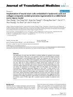
Figure 1 shows a typical SEM image of GaAs/InAs
nanowire heterostructures, in which almost all nanowires
grew perpendicular to the substrate surface, i.e., along the
½
"
1
"
1
"
1 direction. The nanowires are tapered, suggesting that
lateral growth has taken place, particularly in the bottom
region [21]. The inset of Fig. 1 is a TEM image of the top
portion of a typical GaAs/InAs nanowire and shows the
detailed morphology of the GaAs/InAs nanowire with a Au
catalyst at the tip. Since GaAs was deposited for 30 min, it
is anticipated that GaAs lateral growth has taken place
around the InAs nanowires. To understand the lateral
growth behavior of GaAs around InAs nanowires, TEM
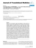
investigations were conducted. Figure 2a shows a TEM
image of GaAs/InAs radial nanowire heterostructure with a
high-magnification image in Fig. 2b. The Moire
´
fringes in
the middle region and stain contrast in the outer region
suggest the core/shell structure. To determine the chemical
compositional characteristics, energy dispersive spectros-
copy (EDS) analysis was performed. Figure 2c shows the
qualitative analysis of EDS line scan across the nanowire,
clearly showing the InAs/GaAs core/shell nanowire het-
erostructure. This EDS analysis shows more quantity of Ga
than In in the core region. We anticipate that such differ-
ence in the quantity is due to higher volume of GaAs shell
than the InAs core. In order to determine the structural
characteristics of these nanowire heterostructures, electron
diffraction is performed. Figure 2d shows a selective area
electron diffraction pattern taken from one of these nano-
wires. Two sets of wurtzite diffraction patterns (along
½
"
2110 zone axis) with their diffraction spots accompanied
by additional double diffraction spots can be seen. This
result suggests that both the GaAs and InAs have the
wurtzite structure. The lattice mismatch between two sets
of diffraction spots can be measured to be *6.5 ± 0.5% in
both the axial and lateral directions, suggesting that the
misfit strain between the two materials is almost relaxed in
both axial and lateral directions and there is no lattice
distortion. To further determine the structural characteris-
tics at atomic level, high-resolution TEM (HRTEM) was
Fig. 1 SEM image of GaAs/InAs nanowire heterostructures, where
the substrate normal is tilted 10° away from the incident electron
beam direction. Inset shows a TEM image of the top portion of a
typical GaAs/InAs nanowire
Nanoscale Res Lett (2009) 4:846–849 847
123
conducted. Figure 2e shows a high-resolution image of the
InAs–GaAs core–shell structure. InAs core region can be
identified by the presence of the strain contrast, and both
the InAs core and the GaAs shell have the wurtzite
structure.
As mentioned earlier, InAs nanowires grown along
h111i
B
directions using MOCVD adopt the wurtzite
structure. However, when GaAs nanowires grow axially
they preserve its bulk crystal structure, the zinc-blende
structure. In fact, when InAs and GaAs were grown alter-
nately along the h111i directions to form axial nanowire
heterostructures, they were observed to have alternating
between wurtzite and zinc-blende crystal structures,
respectively [11]. However, the results shown in this study
and references [12, 13] show that when InAs is sheathed
around GaAs nanowires, the sheathed InAs adopt the zinc-
blende structure; while when GaAs is sheathed over the
InAs nanowires, the sheathed GaAs adopt the wurtzite
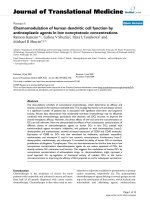
structure. In order to understand this structural difference
between the axial and radial heterostructures, we verify the
lattice registry between zinc-blende and wurtzite crystal
structures by placing both the structures axially and
laterally. Figure 3a shows h1
"
10i projected zinc-blende
structure of GaAs placed above the h
"
2110i projected
wurtzite structure of InAs. Figure 3b shows both the
atomic structures when placed laterally to each other. As
can be seen from Fig. 3a, when these structures are placed
one another along the h111i direction, they can have a
lattice registry between them. In fact, both wurtzite and
zinc-blende structures are stack of {111} or {0001} planes
with a difference in the stacking sequence. Since the
atomic arrangements in both {111} and {0001} planes are
identical, they can coexist when the nanowires grow in
h111i or {0001} directions with a lattice registry between
the two structures. Such a possibility is believed to be the
reason for the coexistence of both wurtzite and zinc-blende
structures even in two-dimensions when they grow in h111i
direction [22].
In the case of lateral direction (Fig. 3b) on the other
hand, both crystal structures cannot have a lattice reg-
istry except for each sixth layer, as shown by the arrows.
In fact, lack of this lattice registry would cause high
energy heterointerfaces, and it is observed that such
energetic conditions would transform the wurtzite
Fig. 2 a Low magnification
TEM images of a GaAs/InAs
nanowire heterostructure. b A
high-magnification TEM image
of the GaAs/InAs nanowire, and
its corresponding EDS line-scan
spectrum across the nanowire is
shown in (c). d An electron
diffraction pattern taken on the
GaAs/InAs core/shell structure.
e High resolution TEM image
showing GaAs/InAs interface
region
848 Nanoscale Res Lett (2009) 4:846–849
123
structure into zinc-blende structure when the wurtzite
nanowires are sheathed with two-dimensional zinc-blende
layers [23]. Similarly, in our current study, the normally
zinc-blende GaAs structure transforms into a wurtzite
structure when brought into contact with the InAs NW
side walls, by nucleating epitaxially on the nanowire
sidewalls.
Conclusions
We have grown InAs/GaAs core/shell structures using
MOCVD method, and the transmission electron micros-
copy investigations show that both the core and shell
contain wurtzite structure. In contrast, when InAs/GaAs
heterostructures grow in h111i or h0001i axial directions,
both the materials can have different crystal structures.
This structural difference between both the axial and lateral
direction is explained in terms of crystallography and
interfacial structure.
Acknowledgments The Australian Research Council is acknowl-
edged for the financial support of this project. M. Paladugu
acknowledges the support of an International Postgraduate Research
Scholarship. The Australian National Fabrication Facility established
under the Australian Government’s National Collaborative Research
Infrastructure Strategy is gratefully acknowledged for access to the
facilities used in this study.
References
1. H.J. Fan, P. Werner, M. Zacharias, Small 2, 700 (2006). doi:
10.1002/smll.200500495
2. A.J. Mieszawska, R. Jalilian, G.U. Sumanasekera, F.P. Zambo-
rini, Small 3, 722 (2007). doi:10.1002/smll.200600727
3. O. Hayden, G.F. Zheng, P. Agarwal, C.M. Lieber, Small 3, 2048
(2007). doi:10.1002/smll.200700600
4. C.J. Novotny, E.T. Yu, P.K.L. Yu, Nano Lett. 8, 775 (2008). doi:
10.1021/nl072372c
5. H.A. Nilsson, T. Duty, S. Abay, C. Wilson, J.B. Wagner, C.
Thelander, P. Delsing, L. Samuelson, Nano Lett. 8, 872 (2008).
doi:10.1021/nl0731062
6. O. Hayden, M.T. Bjork, H. Schmid, H. Riel, U. Drechsler, S.F.
Karg, E. Lortscher, W. Riess, Small 3, 230 (2007). doi:10.1002/
smll.200600325
7. S.A. Dayeh, D.P.R. Aplin, X.T. Zhou, P.K.L. Yu, E.T. Yu, D.L.
Wang, Small 3, 326 (2007). doi:10.1002/smll.200600379
8. N. Wang, Y. Cai, R.Q. Zhang, Mater. Sci. Eng. R Rep. 60, 1 (2008)
9. R.S. Wagner, W.C. Ellis, Appl. Phys. Lett. 4, 89 (1964). doi:
10.1063/1.1753975
10. M. Paladugu, J. Zou, Y.N. Guo, G.J. Auchterlonie, Y. Kim, H.J.
Joyce, Q. Gao, H.H. Tan, C. Jagadish, Small 3, 1873 (2007). doi:
10.1002/smll.200700222
11. M. Paladugu, J. Zou, Y.N. Guo, X. Zhang, Y. Kim, H.J. Joyce, Q.
Gao, H.H. Tan, C. Jagadish, Appl. Phys. Lett. 93, 101911 (2008).
doi:10.1063/1.2978959
12. M. Paladugu, J. Zou, Y.N. Guo, X. Zhang, H.J. Joyce, Q. Gao,
H.H. Tan, C. Jagadish, Y. Kim, Appl. Phys. Lett. 93, 201908
(2008). doi:10.1063/1.3033551
13. M. Paladugu, J. Zou, Y.N. Guo, X. Zhang, H.J. Joyce, Q. Gao,
H.H. Tan, C. Jagadish, Y. Kim, Angew. Chem. Int. Ed. Engl. 48,
780 (2009). doi:10.1002/anie.200804630
14. M. Paladugu, J. Zou, G.J. Auchterlonie, Y.N. Guo, Y. Kim, H.J.
Joyce, Q. Gao, H.H. Tan, C. Jagadish, Appl. Phys. Lett. 91,
133115 (2007). doi:10.1063/1.2790486
15. M.T. Borgstrom, G. Immink, B. Ketelaars, R. Algra, E. Bakkers,
Nat. Nanotechnol. 2, 541 (2007). doi:10.1038/nnano.2007.263
16. F. Qian, Y. Li, S. Gradecak, D.L. Wang, C.J. Barrelet, C.M.
Lieber, Nano Lett. 4, 1975 (2004). doi:10.1021/nl0487774
17. T. Ito, Jpn. J. Appl. Phys. Part 2 – Lett. 37, L1217 (1998)
18. M.I. McMahon, R.J. Nelmes, Phys. Rev. Lett. 95, 215505 (2005).
doi:10.1103/PhysRevLett.95.215505
19. M. Murayama, T. Nakayama, Phys. Rev. B 49, 4710 (1994). doi:
10.1103/PhysRevB.49.4710
20. Z.G. Chen, J. Zou, G. Liu, X.D. Yao, F. Li, X.L. Yuan, T.
Sekiguchi, G.Q. Lu, H.M. Cheng, Adv. Funct. Mater. 18, 3063
(2008). doi:10.1002/adfm.200800447
21. J. Zou, M. Paladugu, H. Wang, G.J. Auchterlonie, Y.N. Guo, Y.
Kim, Q. Gao, H.J. Joyce, H.H. Tan, C. Jagadish, Small
3, 389
(2007). doi:10.1002/smll.200600503
22. V.V. Chaldyshev, B. Nielsen, E.E. Mendez, Y.G. Musikhin, N.A.
Bert, Z. Ma, T. Holden, Appl. Phys. Lett. 86, 131916 (2005). doi:
10.1063/1.1875759
23. G. Patriarche, F. Glas, M. Tchernycheva, C. Sartel, L. Largeau,
J.C. Harmand, Nano Lett. 8, 1638 (2008). doi:10.1021/nl080319y
Fig. 3 a A schematic diagram
showing h1
"
10i projected zinc-
blende structure placed above
the h
"
2110i projected wurtzite
structure, and b shows both the
structures but placed in the
lateral direction
Nanoscale Res Lett (2009) 4:846–849 849
123