Báo cáo hóa học: " Research Article Beamforming under Quantization Errors in Wireless Binaural Hearing Aids" potx
Bạn đang xem bản rút gọn của tài liệu. Xem và tải ngay bản đầy đủ của tài liệu tại đây (1.71 MB, 8 trang )
Hindawi Publishing Corporation
EURASIP Journal on Audio, Speech, and Music Processing
Volume 2008, Article ID 824797, 8 pages
doi:10.1155/2008/824797
Research Article
Beamforming under Quantization Errors in
Wireless Binaural H earing Aids
Sriram Srinivasan, Ashish Pandharipande, and Kees Janse
Philips Research, High Tech Campus 36, 5656AE Eindhoven, The Netherlands
Correspondence should be addressed to Sriram Srinivasan,
Received 28 January 2008; Revised 5 May 2008; Accepted 30 June 2008
Recommended by John Hansen
Improving the intelligibility of speech in different environments is one of the main objectives of hearing aid signal processing
algorithms. Hearing aids typically employ beamforming techniques using multiple microphones for this task. In this paper, we
discuss a binaural beamforming scheme that uses signals from the hearing aids worn on both the left and right ears. Specifically,
we analyze the effect of a low bit rate wireless communication link between the left and right hearing aids on the performance
of the beamformer. The scheme is comprised of a generalized sidelobe canceller (GSC) that has two inputs: observations from
one ear, and quantized observations from the other ear, and whose output is an estimate of the desired signal. We analyze the
performance of this scheme in the presence of a localized interferer as a function of the communication bit rate using the resultant
mean-squared error as the signal distortion measure.
Copyright © 2008 Sriram Srinivasan et al. This is an open access article distributed under the Creative Commons Attribution
License, which permits unrestricted use, distribution, and reproduction in any medium, provided the original work is properly
cited.
1. INTRODUCTION
Modern digital hearing aids perform a variety of signal
processing tasks aimed at improving the quality and intel-
ligibility of the received sound signals. These tasks include
frequency-dependent amplification, feedback cancellation,
background noise reduction, and environmental sound
classification. Among these, improving speech intelligibility
in the presence of interfering sound sources remains one
of the most sought-after features among hearing aid users
[1]. Hearing aids attempt to achieve this goal through
beamforming using two or more microphones, and exploit
the spatial diversity resulting from the different spatial
positions of the desired and interfering sound sources [2].
The distance between the microphones on a single
hearing aid is typically less than 1 cm due to the small size
of such devices for aesthetic reasons. This small spacing
limits the gain that can be obtained from microphone array
speech enhancement algorithms. Binaural beamforming,
which uses signals from both the left and right hearing aids,
offers greater potential due to the larger inter-microphone
distances corresponding to the distance between the two ears
(16–20 cm). In addition, such a scheme also provides the
possibility to exploit the natural attenuation provided by the
head. Depending on the location of the interfering source,
the signal-to-interference ratio (SIR) can be significantly
higher at one ear compared to the other, and a binaural
system can exploit this aspect.
A high-speed wireless link between the hearing aids worn
on the left and right ears has been recently introduced [3].
This allows binaural beamforming without the necessity of
having a wired connection between the hearing aids, which is
impractical again due to aesthetic reasons. The two hearing
aids form a body area network, and can provide significant
performance gains by collaborating with one another. The
performance of binaural noise reduction systems has been
previously studied in, for example, [4–8]. However these
bsystems implicitly assume the availability of the error-free
left and right microphone signals for processing. In practice,
the amount of information that can be shared between the
left and right hearing aids is limited by constraints on power
consumption imposed by the limited capacity of hearing
aid batteries. It is known [9] that quantization of a signal
with an additional bit causes the power dissipation in an
ADC to be increased by 3 dB. Hence to conserve battery
in a hearing aid, it is critical to compress with as few bits
as possible before wireless transmission occurs. One in five
users was reported to be dissatisfied with hearing aid battery
life [10], and it is thus an important consideration in hearing
2 EURASIP Journal on Audio, Speech, and Music Processing
aid design. In this paper, we study analytically the trade-off
in the performance of a GSC beamformer with respect to
quantization bits.
Different configurations are possible for a binaural
beamforming system, for instance, both hearing aids could
transmit their received microphone signals to a central device
where the beamforming is performed, and the result could
then be transmitted back to the hearing aids. Alternatively,
the hearing aids could exchange their signals and beamform-
ing may be performed on each hearing aid. In this paper, to
analyze the effect of quantization errors on beamforming,
without loss of generality we assume that each hearing aid
has one microphone and that the right hearing aid quantizes
and transmits its signal to the left hearing aid, where the two
signals are combined using a beamformer. This paper is an
extension of our earlier work [11], incorporates the effect
of head shadow and presents a more detailed experimental
analysis.
If the power spectral density (PSD) of the desired source
is known a priori, the two-microphone Wiener filter provides
the optimal (in the mean squared error sense) estimate of
the desired source. The effect of quantization errors in such
aframeworkhasbeeninvestigatedin[12]. However, in
practice the PSD is unknown. In this paper, we consider
a particular beamformer, the generalized sidelobe canceller
(GSC) [13], which does not require prior knowledge of the
source PSD.
The GSC requires knowledge of the location of the
desired source, which is available since the desired source
is commonly assumed to be located at 0
◦
(in front of
the microphone array) in hearing aid applications [2]. The
motivation behind this assumption is that in most real-life
situations, for instance, a conversation, the user is facing the
desired sound source. In a free field, the two-microphone
GSC can cancel out an interfering sound source without
distorting the desired signal, which is a desirable feature in
hearing aids. Thus, the GSC is well suited for hearing aid
applications, and we study the impact of quantization errors
on the GSC in this paper.
The performance of the GSC may be affected by other
sources of error such as microphone mismatch, errors in
the assumed model (the desired source may not be located
exactly at 0
◦
), reverberation, and so forth. Variations of the
GSC that are robust to such imperfections are discussed in
[14–16].Inthispaper,weexcludesucherrorsfromour
analysis to isolate the effect of the errors introduced by
quantization on the performance of the GSC.
The remainder of this paper is organized as follows. We
introduce the signal model and the head shadow model we
use in Section 2. The binaural GSC and its behavior in the
presence of quantization errors are discussed in Section 3.
The performance of the GSC at different bit rates is analyzed
in Section 4. Finally, concluding remarks and suggestions for
future work are presented in Section 5.
2. SIGNAL MODEL
Consider a desired source s(n) in the presence of an interferer
i(n), where n represents the time index. A block of N samples
of the desired and interfering signals can be transformed into
the frequency domain using the discrete Fourier transform
(DFT) as
S(k)
=
N−1
n=0
s(n)e
−j2πnk/N
,
I(k)
=
N−1
n=0
i(n)e
−j2πnk/N
,0≤ k<N,
(1)
where k is the frequency index. Let E
{S(k)S
†
(k)}=Φ
s
(k),
and E
{I(k)I
†
(k)}=Φ
i
(k), where † indicates complex
conjugation. We assume that the left and right microphones
each have one microphone. The signal observed at the
microphone in the left hearing aid can be written as
X
L
(k) = H
L
(k)S(k)+G
L
(k)I(k)+U
L
(k), (2)
where H
L
(k)andG
L
(k) are the transfer functions between
the microphone on the left hearing aid and the desired and
interfering sources, respectively, and U
L
(k) corresponds to
uncorrelated (e.g., sensor) noise with E
{U
L
(k)U
†
L
(k)}=
Φ
u
∀k. The transfer functions H
L
(k)andG
L
(k) include the
effect of head shadow. For each k,wemodelS(k), I(k), and
U
L
(k) as memoryless zero mean complex Gaussian sources,
with variances Φ
s
(k), Φ
i
(k), and Φ
u
, respectively. Their real
and imaginary parts are assumed to be independent with
variances Φ
s
(k)/2, Φ
i
(k)/2, and Φ
u
/2, respectively.
The signal observed at the right ear can be written as
X
R
(k) = H
R
(k)S(k)+G
R
(k)I(k)+U
R
(k), (3)
where the relevant terms are defined analogously to the left
ear. We assume that E
{U
R
(k)U
†
R
(k)}=Φ
u
∀k, and that S(k),
I(k), U
L
(k), and U
R
(k) are pairwise independent.
We use the spherical head shadow model described in
[17] to obtain the head related transfer functions (HRTFs)
H
L
(k), H
R
(k), G
L
(k), and G
R
(k). Define the origin to be the
center of the sphere. Let a be the radius of the sphere, r be the
distance between the origin and the sound source, and define
ρ
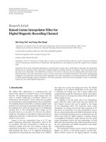
= r/a.Letθ denote the angle between a ray from the origin
to the sound source and a ray from the origin to the point of
observation (left or right ear) on the surface of the sphere as
shown in Figure 1. The HRTF corresponding to the angle of
incidence θ is then given by [17]
H(ρ, k,θ)
=−
ρc
ka
exp
−
j
2πk
N
a
c
Ψ(ρ, k, θ), (4)
with
Ψ(ρ, k, θ)
=
∞
m=0
(2m +1)P
m
(cos θ)
h
m
((2πk/N)ρa/c)
h
m
((2πk/N)a/c)
,(5)
where P
m
is the Legendre polynomial of degree m, h
m
is the
spherical Hankel function of order m,andh
m
is the derivative
of h
m
with respect to its argument.
Let θ
s
denote the angle between the vertical y-axis and a
ray from the origin to the desired source. Let θ
i
be defined
similarly for the interfering source. The microphones on the
Sriram Srinivasan et al. 3
5π
9
θ
s
θ
r
a
Source
Left Right
Figure 1: The head shadow model. The left and right hearing aids
each have one microphone and are located at
±5π/9 on the surface
of a sphere of radius a.
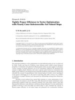
Fixed
beamformer
Blocking
matrix
W(k)
X
L
(k)
X
R
(k)
Y
b
(k)
Y
r
(k)
Z(k)
−
Figure 2: Frequency-domain implementation of the GSC.
left and right hearing aids are assumed to be located at 5π/9
and
−5π/9, respectively, on the surface of the sphere. For
example, if in Figure 1, θ
s
=−π/3, then the location of the
source relative to the left ear is
−θ
s
+5π/9 = 8π/9. We have
H
L
(k) = H(ρ,k, −θ
s
+5π/9),
H
R
(k) = H(ρ,k, −θ
s
−5π/9).
(6)
Similarly, the transfer functions corresponding to the inter-
ferer are given by
G
L
(k) = H(ρ,k, −θ
i
+5π/9),
G
R
(k) = H(ρ,k, −θ
i
−5π/9).
(7)
We consider the case where the quantities θ
i
, Φ
s
(k),
Φ
i
(k), and Φ
u
are all unknown. As is typical in hearing
aid applications [2], we assume the desired source to be
located in front of the user, that is, θ
s
= 0
◦
. Thus, due
to symmetry, the HRTFs between the desired source and
the left and right microphones are equal (this is valid in
anechoic environments, and only approximately satisfied in
reverberant rooms). Let H
L
(k) = H
R
(k) = H
s
(k). The GSC
structure [13] depicted in Figure 2 can then be applied in
this situation. The fixed beamformer simply averages its two
inputs as the desired source component is identical in the
two signals. The blocking matrix subtracts the input signals
resulting in a reference signal that is devoid of the desired
signal, and forms the input to the adaptive interference
canceller.
We assume that the hearing aid at the right ear quantizes
and transmits its signal to the hearing aid at the left ear where
the two are combined. Let
X
R
(k) represent the reconstructed
signal obtained after encoding and decoding X
R
(k)atarate
R
k
bits per sample resulting in a distortion D
k
,whereD
k
=
E{|X
R
(k)−
X
R
(k)|
2
}.Theforward channel with respect to the
squared error criterion can be written as [18, pages 100-101],
X
R
(k) = α
k
(X
R
(k)+V(k)), (8)
where α
k
= (Φ
x
(k) − D
k
)/Φ
x
(k), Φ
x
(k) = E{X
R
(k)X
†
R
(k)},
and V(k) is zero mean complex Gaussian with variance
D
k
/α
k
. Recall that we model S(k), I(k), U
L
(k), and U
R
(k)as
memoryless zero mean complex Gaussian random sources
for each k, with independent real and imaginary parts. The
rate-distortion relation for the complex Gaussian source
follows from the rate-distortion function for a real Gaussian
source [18, Chapter 4],
R
k
(D
k
) = log
2
Φ
x
(k)
D
k
,(9)
so that the distortion D
k
is obtained as D
k
= Φ
x
(k)2
−R
k
.The
signals X
L
(k)and
X
R
(k) form the two inputs to the GSC.
If the PSDs Φ
s
(k), Φ
i
(k), and Φ
u
are known, more
efficient quantization schemes may be designed, for example,
one could first estimate the desired signal (using a Wiener
filter) from the noisy observation X
R
at the right ear, and then
quantize the estimate as in [12]. However, as the PSDs are
unknown in our model, we quantize the noisy observation
itself.
3. THE BINAURAL GSC
We first look at the case when there is no quantization
and the left hearing aid receives an error-free description
of X
R
(k). This corresponds to an upper bound in our
performance analysis. We then consider the case when X
R
(k)
is quantized at a rate R
k
bits per sample.
3.1. No quantization
The GSC has three basic building blocks. The first is a
fixed beamformer that is steered towards the direction of
the desired source. The second is a blocking matrix that
produces a so-called noise reference signal that is devoid of
the desired source signal. Finally, the third is an adaptive
interference canceller that uses the reference signal generated
by the blocking matrix to cancel out the interference present
in the beamformer output.
The output of the fixed delay-and-sum beamformer is
given by
Y
b
(k) = F(k)X(k), (10)
where F(k)
= (1/2)[1 1], X(k) = [X
L
(k) X
R
(k)]
T
.Wecan
rewrite Y
b
(k)as
Y
b
(k) = H
s
(k)S(k)+
1
2
I(k)(G
L
(k)+G
R
(k))
+
1
2
(U
L
(k)+U
R
(k)).
(11)
4 EURASIP Journal on Audio, Speech, and Music Processing
The blocking matrix is given by B(k) = [1 − 1], so that the
input to the adaptive interference canceller W(k) is obtained
as
Y
r
(k) = B(k)X(k)
= I(k)(G
L
(k) − G
R
(k)) + U
L
(k) − U
R
(k).
(12)
The adaptive filter W(k) is updated such that the expected
energy of the residual given by η
k
= E{|Y
b
(k) −
W(k)Y
r
(k)|
2
} is minimized, for example, using the nor-
malized least mean square algorithm [19,Chapter9].Since
Y
r
(k) does not contain the desired signal, minimizing η
k
corresponds to minimizing the energy of the interferer in the
residual. Note that none of the above steps require knowledge
of the PSD of the desired or interfering sources.
For our analysis, we require the optimal steady state
(Wiener) solution for W(k), which is given by
W
opt
(k) =
E{Y
b
(k)Y
†
r
(k)}
E{Y
r
(k)Y
†
r
(k)}
, (13)
where
E
{Y
b
(k)Y
†
r
(k)}=
1
2
Φ
i
(k)(G
L
(k)+G
R
(k))(G
L
(k) − G
R
(k))
†
E{Y
r
(k)Y
†
r
(k)}=Φ
i
(k)|G
L
(k) − G
R
(k)|
2
+2Φ
u
.
(14)
TheGSCoutputcanbewrittenas
Z(k)
= Y
b
(k) − W
opt
(k)Y
r
(k), (15)
and the resulting estimation error is
ξ
k
= E{(H
s
(k)S(k) −Z(k))(H
s
(k)S(k) −Z(k))
†
}
=
E{Y
b
(k)Y
†
b
(k)}−E{Y
b
(k)Y
†
r
(k)}W
†
opt
(k)
−|H
s
(k)|
2
Φ
s
(k),
(16)
where
E
{Y
b
(k)Y
†
b
(k)}=|H
s
(k)|
2
Φ
s
(k)
+
1
4
Φ
i
(k)|G
L
(k)+G
R
(k)|
2
+
1
2
Φ
u
.
(17)
3.2. Quantization at a rate R
Thebeamformeroutputinthiscaseisgivenas
Y
b
(k) =
1
2
(X
L
(k)+
X
R
(k))
=
1
2
(1 + α
k
)H
s
(k)S(k)+
1
2
I(k)(G
L
(k)+α
k
G
R
(k))
+
1
2
(U
L
(k)+α
k
U
R
(k)) +
1
2
α
k
V(k).
(18)
Comparing (18)with(11), since 0
≤ α
k
≤ 1, it can be seen
that while the fixed beamformer preserves the desired source
in the unquantized case, there is attenuation of the desired
source in the quantized case. The blocking matrix produces
Y
r
(k) = (1 −α
k
)H
s
(k)S(k)+I(k)(G
L
(k) − α
k
G
R
(k))
+ U
L
(k) − α
k
U
R
(k) − α
k
V(k).
(19)
It is evident from (19) that due to the quantization, the
reference signal
Y
r
(k) is not completely free of the desired
signal S(k), which will result in some cancellation of the
desired source in the interference cancellation stage. The
adaptive interference canceller is given by
W
opt
(k) =
E{
Y
b
(k)
Y
†
r
(k)}
E{
Y
r
(k)
Y
†
r
(k)}
, (20)
where
E
{
Y
b
(k)
Y
†
r
(k)}=
1
2
(1
−α
2
k
)|H
s
(k)|
2
Φ
s
(k)
+
1
2
Φ
i
(k)(G
L
(k)+α
k
G
R
(k))
×(G
L
(k) − α
k
G
R
(k))
†
+
1
2
(1
−α
2
k
)Φ
u
−
1
2
α
2
k
Φ
v
(k),
E
{
Y
r
(k)
Y
†
r
(k)}=(1 − α
k
)
2
|H
s
(k)|
2
Φ
s
(k)
+ Φ
i
(k)|G
L
(k) − α
k
G
R
(k)|
2
+(1+α
2
k
)Φ
u
+ α
2
k
Φ
v
(k),
(21)
where Φ
v
(k) = E{V(k)V
†
(k)}. The GSC output in this case
is
Z(k) =
Y
b
(k) −
W
opt
(k)
Y
r
(k). (22)
The corresponding estimation error is
ξ
k
(R
k
) = E{(H
s
(k)S(k) −
Z(k))(H
s
(k)S(k) −
Z(k))
†
}
=
P
z
(k) − α
k
|H
s
(k)|
2
Φ
s
(k)
+(1
−α
k
)|H
s
(k)|
2
Φ
s
(k)(
W
opt
(k)+
W
†
opt
(k)),
(23)
where
P
z
(k) = E{
Z(k)
Z
†
(k)}
=
E{
Y
b
(k)
Y
†
b
(k)}−E{
Y
b
(k)
Y
†
r
(k)}
W
†
opt
(k),
E
{
Y
b
(k)
Y
†
b
(k)}=
1
4
(1 + α
k
)
2
|H
s
(k)|
2
Φ
s
(k)
+
1
4
Φ
i
(k)|G
L
(k)+α
k
G
R
(k)|
2
+
1
4
(1 + α
2
k
)Φ
u
+
1
4
α
2
k
Φ
v
(k).
(24)
4. GSC PERFORMANCE AT DIFFERENT BIT RATES
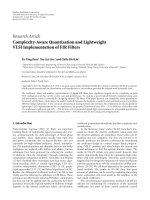
Using (23)-(24), the behavior of the GSC can be studied
at different bit rates, and for different locations of the
interferer. The solid curves in Figure 3 plot the output signal-
to-interference-plus-noise ratio (SINR) obtained from the
binaural GSC at different bit rates for an interferer located
at 40
◦
. The output SINR per frequency bin is obtained as
SINR
out
(k) = 10 log
10
|H
s
(k)|
2
Φ
s
(k)
ξ
k
(R
k
)
. (25)
Sriram Srinivasan et al. 5
0
10
20
30
40
SINR
out
(dB)
2468
Frequency (kHz)
1
3
5
7
9
∞
Figure 3: SINR after processing for input SIR 0 dB, input SNR
30 dB, and interferer located at 40
◦
. Solid curves correspond to
binaural GSC at the specied bit rates (bits per sample), and the
dotted curve corresponds to the monaural case.
For comparisons, we also plot the output SINR obtained
using a monaural two-microphone GSC (dotted line). This
would be the result obtained if there was only a single hearing
aid on the left ear with the two microphones separated by
8 mm in an end-fire configuration. In the monaural case,
we consider a rate R
=∞as both microphone signals are
available at the same hearing aid. To obtain Figure 3, the
relevant parameter settings were Φ
s
(k) = Φ
i
(k) = 1 ∀k,
a
= 0.0875 m, d = 0.008 m, r = 1.5m, and c = 343 m/s.
The mean input SIR and signal-to-noise ratio (SNR) were
set to 0 dB and 30 dB, respectively, where
SIR
=
1
N
N
k=1
10 log
10
|H
s
(k)|
2
Φ
s
(k)
|G
L
(k)|
2
Φ
i
(k)
,
SNR
=
1
N
N
k=1
10 log
10
|H
s
(k)|
2
Φ
s
(k)
Φ
u
.
(26)
It can be seen from Figure 3 that at a rate of 5 bits
per sample, the binaural system outperforms the monaural
system. Note that by bits per sample we mean bits allocated
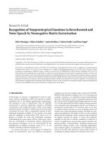
to each sample per frequency bin. Figure 4 shows the
performance of the binaural GSC without considering the
effect of head shadow, that is, assuming that the microphones
are mounted in free space. In this case, the transfer functions
H
s
(k), G
L
(k), and G
R
(k) correspond to the appropriate
relative delays. The sharp nulls in Figure 4 correspond
to those frequencies where it is impossible to distinguish
between the locations of the desired and interfering sources
due to spatial aliasing, and thus the GSC does not provide
any SINR improvement. It is interesting to note that the
differences introduced by head shadow helps in this respect,
as indicated by the better performance at these frequencies in
Figure 3.
0
10
20
30
40
SINR
out
(dB)
2468
Frequency (kHz)
1
3
5
7
9
∞
Figure 4: SINR after processing for input SIR 0 dB, input SNR
30 dB, and interferer located at 40
◦
, ignoring the effect of head
shadow (microphone array mounted in free space). Solid curves
correspond to binaural GSC at the specied bit rates (bits per
sample), and the dotted curve corresponds to the monaural case.
0
10
20
30
40
SINR
out
(dB)
2468
Frequency (kHz)
1
3
5
7
9
∞
Figure 5: SINR after processing for input SIR 0 dB, input SNR
30 dB, and interferer located at 120
◦
. Solid curves correspond to
binaural GSC at the specied bit rates (bits per sample), and the
dotted curve corresponds to the monaural case.
The performance of the monaural system varies signif-
icantly based on the interferer location. When the desired
source and interferer are located close together as in the
case of Figure 3, the small end fire microphone array cannot
perform well due to the broad main lobe of the beamformer.
When the interferer is located in the rear half plane, the
monaural system offers good performance, especially at high
frequencies. Figure 5 plots the output SINR under the same
conditions as in Figure 3 except that the interferer is now
located at 120
◦
, and thus there is a larger separation between
the desired (located at 0
◦
) and interfering sources. The
monaural system (dotted line) performs better than when
6 EURASIP Journal on Audio, Speech, and Music Processing
−10
0
10
20
30
G
SINR
0
10
20
30
SIR
0
10
20
30
SNR
Figure 6: Improvement in SINR after processing at 4 bits per
sample for interferer located at 40
◦
, and for different values of SIR
and SNR.
−10
0
10
20
30
G
SINR
0
10
20
30
SIR
0
10
20
30
SNR
Figure 7: Improvement in SINR after processing at 8 bits per
sample for interferer located at 40
◦
, and for different values of SIR
and SNR.
the interferer was located at 40
◦
. In this case, the binaural
system needs to operate at a significantly higher bit rate to
outperform the monaural system, and the benefits are mainly
in the low-frequency range up to 4 kHz.
For an interferer located at 40
◦
, Figure 6 depicts the
improvement in SINR averaged over all frequencies after
processing by the GSC, for different values of the SIR and
SNR. The improvement was calculated as
G
SINR
=
1
N
N
k=1
10 log
10
|H
s
(k)|
2
Φ
s
(k)
ξ
k
(R
k
)
−
1
N
N
k=1
10 log
10
|H
s
(k)|
2
Φ
s
(k)
|G
L
(k)|
2
Φ
i
(k)+Φ
u
.
(27)
The largest improvements are obtained at low SIRs and high
SNRs, where the adaptive interference canceller is able to
perform well as the level of the interferer is high compared to
the uncorrelated noise in the reference signal Y
r
(k). At high
SIR and low SNR values, the improvement reduces to the
3 dB gain resulting from the reduction of the uncorrelated
noise due to the doubling of microphones. For low SNR
0
10
20
30
G
SINR
(dB)
16 32 48 64 80 96 112 128
Rate (kbps)
Figure 8: Improvement in SINR after processing averaged across all
frequencies at different bit rates (kbps) for uniform rate allocation
(solid) and greedy rate allocation (dotted).
values, the improvement due to the interference canceller
is limited across the entire range of SIR values. However,
as the SNR increases, the interference canceller provides a
significant improvement in performance as can be seen in
the right rear part of Figures 6 and 7.AthighSNRand
SIR values, a low bit rate (e.g., 4 bits per sample) results in
degradation of performance as the loss due to quantization
more than offsets the gain due to beamforming. At low bit
rates, the reference signal
Y
r
(k), which forms the input to
the adaptive interference canceller, is no longer devoid of
the desired signal. This is one of the reasons for the poor
performance of the binaural GSC at low bit rates as the
adaptive filter cancels some of the desired signal. In fact, as
observed in [20], in the absence of uncorrelated noise, the
SIR at the output of the adaptive interference canceller is the
negative (on a log scale) of the SIR in
Y
r
(k). At high input
SIRs and SNRs, even a small amount of desired signal leakage
results in a high SIR in
Y
r
(k), which in turn results in a low
SIR at the output as seen in Figure 6. One approach to avoid
cancellation of the desired signal is to adapt the filter only
when the desired signal is not active [21]. The detections may
be performed, for example, using the method of [22].
So far, we have looked at the effect of quantization at a
bit-rate R independently with respect to each frequency bin.
In practice, the available R bits need to be optimally allocated
to each frequency band k. The rate allocation problem can be
formulated as
{R
∗
1
, R
∗
2
, , R
∗
N
}= argmin
{R
1
,R
2
, ,R
N
}
N
k=1
ξ
k
(R
k
)
subject to
N
k=1
R
k
= R.
(28)
A uniform rate allocation across the different frequency
bins cannot exploit the dependence of the output SINR on
frequency as seen in Figures 3 and 5, and thus a nonuniform
Sriram Srinivasan et al. 7
−40
−20
0
20
40
Φ
s
(k)(dB)
02468
Frequency (kHz)
Figure 9: The PSD Φ
s
(k), of a segment of the signal used to obtain
the results in Figure 8.
scheme is necessary. The distortion function
ξ
k
(R
k
)doesnot
lend itself to a closed-form solution for the rate allocation,
and suboptimal approaches such as a greedy allocation
algorithm need to be employed. In a greedy rate allocation
scheme, at each iteration, one bit is allocated to the band
k where the additional bit results in the largest decrease in
distortion. The iterations terminate when all the available
bits are exhausted. Figure 8 shows the output SINR (averaged
across all frequencies) at different bit rates for both uniform
and greedy rate allocation. Here, the desired and interfering
signals were assumed to be speech. The signals, sampled at
16 kHz, were processed in blocks of N
= 512 samples, and
the results were averaged over all blocks. Figure 9 shows the
PSD of a segment of the signal. It can be seen from Figure 8
that the greedy allocation (dotted) scheme results in better
performance compared to the uniform rate allocation (solid)
scheme. However, we note that the greedy algorithm requires
knowledge of the PSDs Φ
s
(k)andΦ
i
(k), and the location of
the interferer.
5. CONCLUSIONS
A wireless data link between the left and right hearing
aids enables binaural beamforming. Such a binaural system
with one microphone on each hearing aid offers improved
noise reduction compared to a two-microphone monaural
hearing aid system. The performance gain arises from the
larger microphone spacing and the ability to exploit the head
shadow effect. The binaural benefit (improvement compared
to the monaural solution) is largest when an interfering
source is located close to the desired source, for instance,
in the front half plane. For interferers located in the rear
half plane, the binaural benefit is restricted to the low-
frequency region where the monaural system has poor spatial
resolution. Unlike the monaural solution, the binaural GSC
is able to provide a uniform performance improvement
regardless of whether the interferer is in the front or rear half
plane.
Wireless transmission is power intensive and battery
life is an important factor in hearing aids. Exchange of
microphone signals at low bit rates is thus of interest to
conserve battery. In this paper, the performance of the
binaural system has been studied as a function of the
communication bit rate. The generalized sidelobe canceller
(GSC) has been considered in this paper as it requires neither
knowledge of the source PSDs nor of the location of the
interfering sources. Both the monaural and binaural systems
perform best when the level of uncorrelated noise is low, that
is, at high SNRs, when the adaptive interference canceller is
able to fully exploit the availability of the second signal. At an
SNR of 30 dB and an SIR of 0 dB, the binaural system offers
significant gains (15 dB SINR improvement for interferer at
40
◦
) even at a low bit rate of 4 bits per sample. At higher input
SIRs, a higher bit-rate is required to achieve a similar gain.
In practice, the total number of available bits needs
to be optimally allocated to different frequency bands. An
optimal allocation would be nonuniform across the different
bands. Such an allocation however requires knowledge of the
source PSD and the location of the interferer. Alternatively, a
suboptimal but practically realizable uniform rate allocation
may be employed. It has been seen that such a uniform rate
allocation results in a performance degradation of around
5 dB in terms of SINR compared to a nonuniform allocation
obtained using a greedy optimization approach.
The main goal of this paper has been to investigate the
effect of quantization errors on the binaural GSC. Several
extensions to the basic theme can be followed. Topics for
future work include studying the effect of reverberation
and ambient diffuse noise on the performance of the
beamformer. Binaural localization cues such as interaural
time and level differences have been shown to contribute
towards speech intelligibility. Future work could analyze the
effect of quantization errors on these binaural cues.
REFERENCES
[1] S. Kochkin, “MarkeTrak V: ‘Why my hearing aids are in the
drawer’: the consumers’ perspective,” The Hearing Journal, vol.
53, no. 2, pp. 34–42, 2000.
[2] V. Hamacher, J. Chalupper, J. Eggers, et al., “Signal processing
in high-end hearing aids: state of the art, challenges, and future
trends,” EURASIP Journal on Applied Signal Processing, vol.
2005, no. 18, pp. 2915–2929, 2005.
[3] Oticon, “True binaural sound processing in new Oti-
con Epoq signals paradigm shift in hearing care,” Press
release, April 2007, />da/Information/
PressReleases/downloads/epoq
april2007.pdf.
[4] M. Dorbecker and S. Ernst, “Combination of two-channel
spectral subtraction and adaptive Wiener post-filtering for
noise reduction and dereverberation,” in Proceedings of Euro-
pean Signal Processing Conference (EUSIPCO ’96), pp. 995–
998, Trieste, Italy, September 1996.
[5]J.G.Desloge,W.M.Rabinowitz,andP.M.Zurek,
“Microphone-array hearing aids with binaural output—I:
fixed-processing systems,” IEEE Transactions on Speech and
Audio Processing, vol. 5, no. 6, pp. 529–542, 1997.
[6] D.P.Welker,J.E.Greenberg,J.G.Desloge,andP.M.Zurek,
“Microphone-array hearing aids with binaural output—II:
8 EURASIP Journal on Audio, Speech, and Music Processing
a two-microphone adaptive system,” IEEE Transactions on
Speech and Audio Processing, vol. 5, no. 6, pp. 543–551, 1997.
[7] V. Hamacher, “Comparison of advanced monaural and
binaural noise reduction algorithms for hearing aids,” in
Proceedings of IEEE International Conference on Acoustic,
Speech, and Signal Processing (ICASSP ’02), vol. 4, pp. 4008–
4011, Orlando, Fla, USA, May 2002.
[8] T. J. Klasen, S. Doclo, T. van den Bogaert, M. Moonen,
and J. Wouters, “Binaural multi-channel wiener filtering for
hearing aids: preserving interaural time and level differences,”
in Proceedings of IEEE International Conference on Acoustics,
Speech and Sig nal Processing (ICASSP ’06), vol. 5, pp. 145–148,
Toulouse, France, May 2006.
[9] R. H. Walden, “Analog-to-digital converter survey and analy-
sis,” IEEE Journal on Selected Areas in Communications, vol. 17,
no. 4, pp. 539–550, 1999.
[10] S. Kochkin, “MarkeTrak VII: customer satisfaction with
hearing instruments in the digital age,” The Hearing Journal,
vol. 58, no. 9, pp. 30–43, 2005.
[11] S. Srinivasan, A. Pandharipande, and K. Janse, “Effect of
quantization on beamforming in binaural hearing aids,” in
Proceedings of the 3rd International Conference on Body Area
Networks, Tempe, Ariz, USA, March 2008.
[12] O. Roy and M. Vetterli, “Collaborating hearing aids,” in
Proceedings of MSRI Workshop on Mathematics of Relaying
and Cooperation in Communication Networks, Berkeley, Calif,
USA, April 2006.
[13] L. Griffiths and C. Jim, “An alternative approach to linearly
constrained adaptive beamforming,” IEEE Transactions on
Antennas and Propagation, vol. 30, no. 1, pp. 27–34, 1982.
[14] O. Hoshuyama, A. Sugiyama, and A. Hirano, “A robust
adaptive beamformer for microphone arrays with a blocking
matrix using constrained adaptive filters,” IEEE Transactions
on Signal Processing, vol. 47, no. 10, pp. 2677–2684, 1999.
[15] W. Herbordt and W. Kellermann, “Frequency-domain inte-
gration of acoustic echo cancellation and a generalized
sidelobe canceller with improved robustness,” European Trans-
actions on Telecommunications , vol. 13, no. 2, pp. 123–132,
2002.
[16] B J. Yoon, I. Tashev, and A. Acero, “Robust adaptive beam-
forming algorithm using instantaneous direction of arrival
with enhanced noise suppression capability,” in Proceedings
of IEEE International Conference on Acoustics, Speech and
Signal Processing (ICASSP ’07), vol. 1, pp. 133–136, Honolulu,
Hawaii, USA, April 2007.
[17] R. O. Duda and W. L. Martens, “Range dependence of the
response of a spherical head model,” The Journal of the
Acoustical Society of America, vol. 104, no. 5, pp. 3048–3058,
1998.
[18] T. Berger, Rate Distortion Theory: A Mathematical Basis for
Data Compression, Information and System Sciences Series,
Prentice-Hall, Englewood Cliffs, NJ, USA, 1971.
[19] S. Haykin, Adaptive Filter Theory, Prentice-Hall, Englewood
Cliffs, NJ, USA, 3rd edition, 1995.
[20]B.Widrow,J.R.GloverJr.,J.M.McCool,etal.,“Adaptive
noise cancelling: principles and applications,” Proceedings of
the IEEE, vol. 63, no. 12, pp. 1692–1716, 1975.
[21] D. van Compernolle, “Switching adaptive filters for enhanc-
ing noisy and reverberant speech from microphone array
recordings,” in Proceedings of IEEE International Conference on
Acoustics, Speech and Signal Processing (ICASSP ’90), vol. 2, pp.
833–836, Albuquerque, NM, USA, April 1990.
[22] S. Srinivasan and K. Janse, “Spatial audio activity detection for
hearing aids,” in Proceedings of IEEE International Conference
on Acoustic, Speech, and Signal Processing (ICASSP ’08) ,pp.
4021–4024, Las Vegas, Nev, USA, March-April 2008.