Báo cáo hóa học: " Research Article An Adaptive Fair-Distributed Scheduling Algorithm to Guarantee QoS for Both VBR and CBR Video " docx
Bạn đang xem bản rút gọn của tài liệu. Xem và tải ngay bản đầy đủ của tài liệu tại đây (1.22 MB, 12 trang )
Hindawi Publishing Corporation
EURASIP Journal on Advances in Signal Processing
Volume 2008, Article ID 264790, 12 pages
doi:10.1155/2008/264790
Research Article
An Adaptive Fair-Distributed Scheduling Algorithm
to Guarantee QoS for Both VBR and CBR Video Traffics
on IEEE 802.11e WLANs
Saeid Montazeri,
1
Mahmood Fathy,
2
and Reza Berangi
2
1
Computer Group, Islamic Azad University, KhomeiniShahr Branch, Khomeinishar 84175/119, Iran
2
Department of Computer Enginee ring, Iran University of Science and Technology, Tehran 16846-13114, Iran
Correspondence should be addressed to Saeid Montazeri,
Received 2 October 2007; Revised 15 February 2008; Accepted 16 April 2008
Recommended by Jianfei Cai
Most of the centralized QoS mechanisms for WLAN MAC layer are only able to guarantee QoS parameters for CBR video traffic
effectively. On the other hand, the existing distributed QoS mechanisms are only able to differentiate between various traffic
streams without being able to guarantee QoS. This paper addresses these deficiencies by proposing a new distributed QoS scheme
that guarantees QoS parameters such as delay and throughput for both CBR and VBR video traffics. The proposed scheme is also
fair for all streams and it can adapt to the various conditions of the network. To achieve this, three fields are added to the RTS/CTS
frames whose combination with the previously existing duration field of RTS/CTS frames guarantees the periodic fair adaptive
access of a station to the channel. The performance of the proposed method has been evaluated with NS-2. The results showed
that it outperforms IEEE 802.11e HCCA.
Copyright © 2008 Saeid Montazeri et al. This is an open access article distributed under the Creative Commons Attribution
License, which permits unrestricted use, distribution, and reproduction in any medium, provided the original work is properly
cited.
1. INTRODUCTION
The wireless LAN (WLAN) systems have received increasing
popularity in recent years because they are cost effective,
comfortable, and have high capacity. On the other hand,
using video applications has been very popular in recent
years. Therefore, effective using of video streams over the
WLANs is an obligation these days. To achieve this goal, QoS
parameters should be supported over WLANs.
Supporting QoS requirements in WLANs can be done
in two ways: prioritized QoS and guaranteed QoS. A
prioritized-QoS WLAN can only prioritize between different
traffic streams while a guaranteed-QoS WlAN can guarantee
QoS parameters such as delay, jitter, and throughput for
traffic streams. Implementing QoS, either prioritized or
guaranteed, is a challenge in WLAN because there are a
large number of streams with different QoS requirements
in a WLAN. Also some QoS requirements have variable
characteristics during the time like a VBR video traffic.
These characteristics lead to an adaptive QoS supporting
approach in WLANs. In addition to the large number of
streams and QoS requirements which vary during the time,
wireless channel capacity is limited and must be shared
among streams fairly. Thus, an adaptive fair algorithm which
can guarantee QoS parameters is necessary in WLANs.
IEEE task group “e” worked on the support of QoS
in a new standard, called IEEE 802.11e [1]. It introduces
a new access method called hybrid coordination function
(HCF), which combines functions from the DCF and
PCF mechanisms in IEEE 802.11. HCF has two access
mechanisms: enhanced distributed channel access (EDCA)
and controlled channel access mechanism (HCCA). These
two methods support QoS, which will be described further.
In the HCCA, there is a scheduler for scheduling different
traffic streams (TSs) on different stations. The HCCA can
guarantee QoS parameters but it needs a centralized device
that is called point coordinator (PC). On the other hand,
the EDCA which does not use any PC could not guarantee
QoS parameters. It can only operate for high-priority traffics
sufficiently so it is not a fair method. In addition, both HCCA
and EDCA have to tolerate high overhead to adapt to the
network conditions.
ManyworkshavebeendonetoimproveQoSintheIEEE
802.11e MAC layer. These works can be divided into two
2 EURASIP Journal on Advances in Signal Processing
categories: the works that improve QoS distributively and the
works which improve QoS by using PC.
In [2], the authors proposed a new adaptive fair-
distributed method. This method enhances the EDCA of
IEEE 802.11e by increasing the contention window when
the channel is busy. It also uses an adaptive fast backoff
mechanism when the channel is idle. They computed an
adaptive backoff threshold for each priority level by taking
into account the channel load. In [3], the authors proposed
a fully distributed MAC adaptation method. They achieve
this by updating the MAC layer parameters like contention
window based on the network condition. Adaptive EDCA
is a new method based on the IEEE 802.11e EDCA that
is proposed in [4]. The main idea in this method is to
decrease CW [i] after a successful transmission and increase
it after a collision slower than it is done in the EDCA.
Also it takes into account both the network condition and
application requirements. An improved EDCA is achieved
in [5] by using the new backoff algorithm called age-
dependent backoff (ADB). ADB changes the persistence
factor by using the age of packets in the transmission
queue and their lifetime. In [6], the authors proposed a
mechanism called A-DRAFT that supports both absolute
and relative throughputs in adaptive distributed manner.
This mechanism also provides fair throughput support with
low variation. In [7],anewmechanismcalleddifferentiated
service EDCA (DSEDCA) was proposed to provide both
strict priority and proportional fair service for IEEE 802.11
WLANs. In this mechanism, resource is allocated to flows
of higher priority, then the remaining bandwidth is shared
proportionally among the other service class according to
their assigned weights. In [8], authors proposed a surplus
TXOP diverter (STXD) scheduling algorithm which allows
each flow to exploit its granted TXOP time to reduce the
delay when burst packets arrival.
In [9], authors proposed a new scheduling algorithm in
link layer to support multimedia services with guaranteed
QoS in WLAN. Their scheduling algorithm is based on
the HCF. It reduces average packet loss ratio by setting
constant bit-rate (CBR) RT to the highest priority followed
by VBR RT, and after all NRT level. It also uses idle time,
while satisfying required rate allocation, transmission delay
bound, and system throughput. In [10], a fair QoS agent
(FQA) is proposed to provide per-class QoS enhancement
and per-station fair channel access simultaneously. Authors
put the FQA algorithm above the MAC layer which enables
algorithm to be implemented without any change in the
MAC layer. Their algorithm satisfies the fairness in WLAN
MAClayer.In[11], a novel QoS capable station (QSTA)
uplink scheduler along with a QoS capable AP (QAP) HCF
scheduler can provide the QoS requirement of delay bound
for multimedia applications. In [12], the authors proposed a
new scheduling algorithm for IEEE 802.11e which they called
FHCF. It outperforms IEEE 802.11e HCF especially for VBR
traffic. It uses queue length estimation to tune time allocation
to stations. A new scheduling algorithm has been proposed
in [13] which enables the IEEE 802.11e scheduler to work
with different SIs for different TSs in the stations. In [14], the
authors proposed a dynamic bandwidth allocation algorithm
along with the measurement-based call admission control
algorithm which can provide delay guarantee for real-time
flow. It uses a classic feedback control system. There is an
enhancement for IEEE 802.11e HCF in [15] that improves
the admission control unit of HCF. By this method, each
priority has a certain and limited amount of resources.
Although all distributed methods in [2–8]canimprove
EDCA in IEEE 802.11e, they can not guarantee QoS param-
eters in WLANs. However, methods in [9–15] can guarantee
QoS in WLANs, they need point coordinator and cause high
overhead to guarantee QoS parameters for VBR video traffic.
This paper proposes an adaptive fair-distributed scheduling
algorithm (AFDSA) [16] for both VBR and CBR video
traffic streams in WLANs. AFDSA is a distributed method
that operates better than centralized methods in all fields
especially for VBR video traffics with low overhead.
The rest of the paper is organized as follows. The IEEE
802.11e is introduced in Section 2. The properties of AFDSA
algorithm are described in
Section 3. Section 4 describes the
simulation results. The conclusion follows in Section 5.
2. IEEE 802.11e MAC
Hybrid coordination function (HCF) of IEEE 802.11e MAC
has both contention-based access method and polling-based
access method. EDCA introduces the concept of access
categories (ACs), which can be considered as instances of
the DCF access mechanism. It provides support for the
prioritized delivery at each station.
2.1. Enhanced distributed channel access (EDCA)
Like DCF, EDCA uses CSMA/CA protocol to access the
wireless media. It only operates during CP. In EDCA method,
each AC within the stations contends for transmission
opportunity (TXOP) independently. TXOP is defined as the
interval of time when a particular station has the right to
initiate the transmission onto the wireless channel. Each
AC starts the backoff after detecting the channel to be idle
for a time interval equal to the arbitration interframe space
(AIFS). Each AC has its AIFS which depends on the assigned
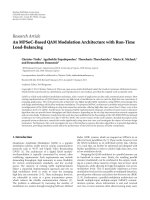
priority. Figure 1 demonstrates the eight different queues for
eight ACs.
Each AC has its own queue, CW
min
[AC], CW
max
[AC],
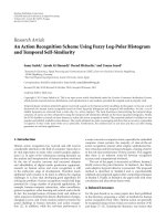
and PF[AC]. Figure 2 shows the different ways to provide
service differentiation.
For each AC, backoff is generated in the range of [1,
CW[AC]+1]. The initial value for the CW is CW
min
[AC].
CW is increased whenever the node involves in a collision
by (1)uptoCW
max
[AC]:
newCW[AC]
=
oldCW[AC] + 1
∗PF[AC]
−1, (1)
where PF is the persistence factor, which equals 2 by default.
It determines the degree of increase for the CW when
Saeid Montazeri et al. 3
802.11e: up to eight independent backoff instances
Legacy:
one priority
Transmission
attempt
Transmission
attempt
Backoff
DIFS
(15)
(2)
Backoff
AIFS
(CW)
(PF)
Backoff
AIFS
(CW)
(PF)
Backoff
AIFS
(CW)
(PF)
Backoff
AIFS
(CW)
(PF)
Backoff
AIFS
(CW)
(PF)
Backoff
AIFS
(CW)
(PF)
Backoff
AIFS
(CW)
(PF)
Backoff
AIFS
(CW)
(PF)
Backoff
AIFS
(CW)
(PF)
NewOld
TC7 TC6 TC6 TC5 TC4 TC3 TC0 TC1 TC2
Higher priority Lower priority
Scheduler (resolves virtual collisions by granting TXOP to highest priority
Figure 1: Old DCF and EDCA.
Vo ic e r a n do m b a ck o ff range
Vo ic e r a n do m b a ck o ff range
Best effort random backoff range
CW
min
[6]
CW
min
[7]
CW
min
[0]
DIFS
Busy medium
Differ access
Contention window
Backoff window
Slot time
Next frame (t)
Select a slot and decrement backof as
long as the medium is idle
Figure 2: Different AIFS for different priorities.
a collision happens. EDCA can only differentiate between
different priorities.
2.2. HCF controlled channel access (HCCA)
In IEEE 802.11e standard, the polling-based scheme of
802.11 is extended in the form of HCCA, in which there
is a hybrid coordinator (HC) usually colocated with a QoS
AP (QAP). HC can access channel after waiting for a time
which is shorter than each AIFS and DIFS. Thus, HC can
get the channel in both CFP and CP. During CP, TXOP
foreachstationcanbereceivedintwoways:byusing
EDCA rules or by receiving a poll from HC (polled
TXOP).
During CFP, TXOP is determined only by HC with poll
frame. CFP is ended by a CF
end frame which is transmitted
by HC.
2.3. 802.11e HCF scheduling scheme
The HCF has a simple scheduler in IEEE 802.11e. If a QoS-
enhanced station (QSTA) needs a strict QoS support, it
should send a QoS requirement packet to the QAP while
the QAP can allocate the corresponding channel time for
different QSTAs according to their requirements. Figure 3
shows the new beacon interval of 802.11e, CFP, and CP.
The QAP can operate in both CFP and CP. During the CP,
the QAP can start several contention-free bursts at any time
to control the channel which are called controlled access
periods (CAPs).
If a station requires a contention-free access to the
channel by getting TXOP, it should send a QoS request frame
to the QAP containing several parameters. These parameters
are mean data rate of the application, the maximum service
4 EURASIP Journal on Advances in Signal Processing
CFP CP
B CAP CAP CAP
Figure 3: CFP, CP, and CAPs in the 802.11e.
interval (MSI) and MAC service data unit (MSDU) size.
Then the QAP calculates the TXOP in two steps. In the first
step, it determines the minimum value of all MSIs required
by different traffic streams. Then, it chooses the highest
submultiples’ value of the 802.11e beacon interval duration
(duration between two beacons) as the selected SI which is
less than the minimum of all requested MSIs. This selected
SI is the time between two successive TXOPs for all streams.
Since it is less than or equal to all MSIs, it is guaranteed that
every station with different streams can reach desired MSI
for their streams. In the second step, the QAP calculates the
TXOP for each TSs in different QSTAs. Calculated TXOP
should correspond to the duration required for transmitting
all packets that is generated during one SI by the specific TS.
Figure 4 shows the CPs, CFPs, selected SI, and EDCA time.
Equations (2)and(3) determine the TXOP, where ρ is the
mean data rate of the application, and L is the MAC service
data unit (MSDU) size:
N
i
=
SI ×ρ
i
L
i
. (2)
Here, N
i
is the number of packets that is generated during
an SI for the ith priority. R is the physical transmission
rate, M is the size of maximum MSDU (2304 bytes), and O
determines the overhead in time units:
TXOP
i
= max
N
i
×L
i
R
i
+ O,
M
R
i
+ O
. (3)
It can be easily deduced that the TXOP
i
is the time required
to send N
i
packets for a specific application.
3. THE PROPOSED ADAPTIVE FAIR-DISTRIBUTED
SCHEDULING ALGORITHM (AFDSA)
3.1. Concept
All centralized channel access methods in WLANs, which
are able to guarantee QoS parameters, have one PC that
knows the QoS requirements of all TSs. These requirements,
which are sent by each station to the PC before starting a
transmission, enable the PC to schedule all TSs. The PC can
manage QSTAs and guarantee QoS because of its awareness
about the requirements of all traffic streams and its ability to
get the channel in desirable time. As a matter of fact, PC polls
the stations in a proper way by using its knowledge about
the network condition. On the other hand, the distributed
methods do not have such a PC or equivalent device to gather
information and guarantee QoS by managing QSTAs.
The most important characteristic of our approach is
to distribute the necessary information (which is different
from the one in IEEE 802.11e) among QSTAs to make
aware all stations about the network situation. The proposed
AFDSA employs the RTS/CTS feature in IEEE 802.11 with
some changes. By using this feature, we can reduce the
overhead which is required for distributing QoS parameters.
The RTS/CTS handshaking mechanism is used to solve the
hidden terminal (hidden node) problem in IEEE 802.11
WLANs. A hidden node problem happens when two stations
that communicate with a common station are not able to
hear each other so their packets collide. Figure 5 demon-
strates RTS/CTS packets in which the frame control field is
related to the control functions, Duration field contains a
value that shows the duration of a transmission, RA is the
receiver address, TA is the transmitter address, and FCS is
the frame check sequence of the packets.
A RTS/CTS protocol initiates with sending an RTS
frame to the receiver (Figure 6). A transmission only starts
when a CTS frame is replied to by the receiver. All the
stations, which receive one of these frames, understand that
a transmission will start and continue for duration equal
to the duration field in the RTS/CTS frames. They set their
network allocation vector (NAV) to the proper value to
prevent themselves from disturbing transmission.
This local hand shaking between transmitter and the
receiver provides an excellent opportunity to distribute
necessary information to guarantee QoS parameters. To
achieve this, the proposed AFDSA uses a modified RTS/CTS
protocol with additional fields in the original IEEE 802.11
RTS/CTS frames. The new fields, that is, CurrentSI, FutureSI,
and remainderSI, as shown in Figure 7,areaddedtoboth
RTS/CTS.
What are the CurrentSI, FutureSI, and remainderSI?
Before defining these fields, we should define service interval.
Service interval is the time between two successive TXOPs
that belong to the specific traffic stream. AFDSA uses this
concept for the service interval (SI). When a WLAN works
with a specific SI, a station can reach the channel for TXOP
seconds and it is repeated each SI seconds. In AFDSA,
CurrentSI is the service interval that the WLAN is working
with at the time of transmission; FutureSI is the service
interval that WLAN will work with after ending present SI;
and remainderSI indicates the time that is remaining until
the end of this service interval (after receiving the RTS/CTS
packets). Also TA (transmitter address) is added to the CTS
frames for the future development. The protocol needs two
timers; a duration timer and a service interval (SI) timer.
The protocol sends the RTS/CTS frames only before the
first few packets in each transmission to reduce the trans-
mission overhead. The exact number of required RTS/CTS
packets will be calculated in the next section. The QoS
parameters can be only guaranteed for a trafficstream(TS)
when the TS can have access to the channel for a special
duration with a specific SI. Duration for ith TS in the jth
QSTA can be obtained from
D
j
i
= N
j
i
∗
M
i
R
+2SIFS+ACK
time
+RTSNumber∗
RTS
time
+CTS
time
+ 2SIFS
−
RTS
time
,
(4)
Saeid Montazeri et al. 5
SI SI SI
802.11e beacon interval
BB
B
CA CA
CF CP
Beacon TXOPi TXOP allocated to QSTAs
TXOP
1
TXOP
2
···
EDCA
TXOP
1
TXOP
2
···
EDCA
TXOP
1
TXOP
2
···
EDCA
Figure 4: Structure of the 802.11e beacon interval.
Frame
control
Duration RA TA FCS
Frame
control
Duration RA FCS
RTS frame CTS frame
Figure 5: RTS/CTS frame structure.
DIFS
Source
RTS DATA
SIFS SIFS SIFS
CTS ACK
Destination
DIFS
NAV (RTS)
NAV (CTS)
Others
Time
Figure 6: RTS, CTS, data, and ACK frames sequence.
Frame
control
F
C
S
Duration RA TA CurrentSI
FutureSI RemainderSI
Figure 7: New RTS/CTS frame structure.
where, D
j
i
is the time required to transmit N
j
i
packets with
the length M
i
, the physical rate R, plus the time required to
transmit RTSNumber of RTS and CTS frames. Here, N
j
i
is
the number of packets in the queue of ith TS in the jth QSTA
at the time of calculating D
j
i
.
The question that is to be answered here is how to
guarantee D
j
i
repeats every SI seconds for the ith TS in the
jth QSTA, without disturbing other QSTAs with different TSs
requirements. Suppose that ith TS in the jth QSTA is the first
one that starts the transmission in the WLAN with using
EDCA method. It calculates D
j
i
andputsitintheduration
field of RTS. Then it sets the CurrentSI and FutureSI with
maximum service interval for ith TS. The jth QSTA transmits
RTS frame and waits for receiving CTS. Destination receives
the RTS and calculates the duration field for CTS by using
Duration
CTS
= Duration
RTS
−
SIFS + CTS
time
. (5)
Then, it transmits the CTS frame to the jth QSTA.
All the QSTAs that receive the RTS or CTS understand a
new transmission will be started with the specific length
(duration field in the RTS/CTS frames) and will be repeated
with a specific period (CurrentSI field in the RTS/CTS
frames). Therefore, they reserve this time for station j by
setting and starting their duration timers with the duration
field of RTS/CTS. They also set and start SI timers with the
CurrentSI field of RTS/CTS as well as saving FutureSI field of
RTS/CTS for the next SI timer restart. Finally, when source
receives the CTS frame, it transmits data frame.
The duration field of RTS is updated by the value of the
duration timer in the source station. After this, all stations
have reserved the allocated turn for the jth station and they
keep silent during this time. It is done by using an array.
Each station has an array and saves the sequence of turns
in it. If a station saves 0 in the ith place in array, it means
that, in the SI, the ith turn is reserved for another station,
yet if it saves 1 in the ith place in array, it means that in
the SI the ith turn is reserved for itself. The exact duration
is announced in the duration field of RTS/CTS by the jth
station and other stations do not need to save the value of
duration field. Therefore, duration field can be varied and
updated each time. It is perfect for VBR video traffics and
can adapt itself to the network condition.
After finishing D
j
i
, all QSTAs start to compete for
accessing the channel based on EDCA method. Suppose that
kth QSTA gets the channel for its lth TS. It fills the duration
field by using (5), and sets the CurrentSI with the value of
CurrentSI of jth QSTA. However, it sets the FutureSI field
with maximum service interval that lth TS required when
6 EURASIP Journal on Advances in Signal Processing
it is equal or less than previous FutureSI (related to ith TS
in the jth QSTA). So, all the QSTAs that receive the new
RTS/CTS understand that they must initialize their SI timer
with FutureSI field of new RTS/CTS at the end of current SI.
Therefore after a number of SIs, the network works with the
sufficient SI. This SI is the minimum of maximum service
intervals for all TSs.
After finishing the first SI, all stations check whether they
have the first turn. They do this by using their arrays. The
station which finds that it has the first turn, that is, jth station,
starts to calculate the D
j
i
and transmit the RTS. All the other
stations keep quiet and wait until they receive an RTS or CTS
frame. If a station receives an RTS/CTS, it starts its duration
timer. When a duration timer goes zero, it is the time to go to
the next turn and search the array. Also requesting stations
must only compete in the free time at the tail of current SI
(as shown in Figure 8).
Now we can describe why AFDSA is sufficient for trans-
mitting video traffics. Other distributed method, EDCA, can
only prioritize between various kinds of streams. As depicted
in Tab le 4,CBRvideotraffic has the lowest priority and after
that comes the VBR video traffic. In a WLAN with different
kinds of streams and using EDCA, the video streams can
not adequately access the channel in competition with other
types of traffics. On the other hand, HCCA method needs
specific characteristics of a stream-like data rate and packet
size to allocate channel to it. However, data rate and packet
size vary during the time for VBR video traffics. As a result,
PC in HCCA method can not allocate the accurate time
to the VBR traffics since it is obliged to select one of the
following two choices. The first one is to allocate the channel
to the VBR streams based on the mean data rate. It leads to
some dropping packets, wasted channel, and increased jitter
and delay because of the great changes in the amount of data.
The other choice is to allocate the channel based on the peak
data rate to prevent the packet loss. It causes to waste the
channel much more than what it may happen in the first
method.
AFDSA can adapt the allocated time of each station for
transmitting packets by using number of packets that are
available in the queue at the beginning of the D
j
i
.Thisleadsto
improve the channel efficiently by letting the others to use the
channel. This prevents packet dropping and channel wasting
simultaneously.
The mentioned channel access process in AFDSA elimi-
nates the need for a point coordinator, though each wireless
station can act as an AP when it is connected to the wired
network. This enhances the survivability of WLANs in case
of an AP failure.
3.2. Special situations
This section reviews the performance of proposed protocol
in special situation that might happen during a period in
which a WLAN works.
3.2.1. Missing the RTS/CTS
It is very important for all the stations to be synchronized
so that their SI timers start and finish on time. If a station
Table 1: Data transmission sequence for a specific TS in AFDGP.
RTS
1
SIFS CTS
1
SIFS
Data
1
SIFS Ack
1
SIFS
RTS
2
SIFS CTS
2
SIFS
Data
2
SIFS Ack
2
SIFS
RTS
3
SIFS CTS
3
SIFS
Data
3
SIFS Ack
3
SIFS
.
.
.
.
.
.
.
.
.
.
.
.
RTS
RTSNumber
SIFS CTS
RTSNumber
SIFS
Data
RTSNumber
SIFS Ack
RTSNumber
SIFS
Data
RTSNumber+1
SIFS Ack
RTSNumber+1
SIFS
Data
RTSNumber+2
SIFS Ack
RTSNumber+2
SIFS
Data
RTSNumber+3
SIFS Ack
RTSNumber+3
SIFS
New station
entering time
SI
Free time
D
1
D
2
··· D
n
D
1
D
2
D
3
Learning period
Learning start time
Figure 8: Free time and learning period.
misses the RTS or CTS, it must wait until it receives the next
RTS or CTS. By receiving the next RTS or CTS, it can use the
duration and remainderSI fields to synchronize itself with the
others because these fields are always up to date. The process
of sending and receiving RTS/CTS repeats RTSNumber times
to assure that all the active stations in the communication
rangehavereceivedatleastoneRTSorCTS.Afterwhichonly
data frames will be transmitted. The RTSNumber depends
on the BER of the channel and increases with increasing
the BER. In our simulation, RTS number is set to 2. Table 1
shows data transmission sequences and shows the impact of
RTSNumber on the data transmission.
3.2.2. Entering a new station to the working WLAN
A new station needs remainderSI, FutureSI, and CurrentSI
to synchronize with a working WLAN. So it must wait until
it receives at least one RTS or CTS and it must wait at least
one SI to learn about network condition. This SI which
is referred to as the learning period is shown in Figure 8.
Any new entering station is prevented to send data during
its learning period. Not having permission to send data in
learning period is a rule in AFDSA. It can only access the
channel based on the EDCA rule in the free time after the
learning period and after it receives at least one RTS or CTS
packet too.
Saeid Montazeri et al. 7
3.2.3. Removing a duration between other durations
If a station stops using its allocated turn related to a specific
TS (e.g., ith TS), it must send special RTS to the receiver
RTSNumber times. Receiver replies to this special RTS by
a special CTS frame. These special RTS/CTS frames mean
that duration will not continue any more. So other stations
that receive these frames understand that they must remove
this special duration and its turn. The RTS duration field is
calculated by
Duration
= RTSNumber∗
RTS
time
+CTS
time
+ 2SIFS
RTS
time
.
(6)
This process will be repeated RTSNumber times to assure
that all the listening stations in the WLAN receive at least
oneRTSorCTSframe.InasmuchastheRTSNumber
depends on the BER, it is possible to set its value based on
the probability of missing RTS or CTS by one station. It is
possible for this value to be less than a special limit. A WLAN
with m station which has an active flow and RTSNumber
gives this probability through (7)to(9)
P
f
RTS/CTS
= 1 −(1 − BER)
RTS
Length
≈ RTS
length
∗BER, (7)
P
f
Station
=
P
f
RTS/CTS
RTSNumber
,(8)
P
f
= 1 −
1 −P
f
Station
n−1
≈ (n −1)∗P
f
Station
,(9)
where P
f
RTS/CTS
is the corruption probability of an RTS or
CTS frame, P
f
Station
is the probability that a station does
not receive any of the sent RTSs or CTSs, and P
f
is the
probability of not receiving even one RTS/CTS by a station
among m
−1 listening stations. By using Table 4 for RTS
length
and assuming that BER is equal to 10
−5
[1], P
f
RTS/CTS
will be
0.00224. The power factor in (8) is RTSNumber rather than
2
∗RTSNumber because in severe situations the listening
station may only receive either RTS or CTS because of
being in the signal range of either RTS transmitter or
CTS transmitter. For a WLAN with 200 active flows and
RTSNumber
= 3, the P
f
is equal to 2.2∗10
−6
.
3.3. AFDSA scalability
Since the AFDSA is a distributed algorithm, it has a good
scalability. It can accept new stations until the channel
saturates, or there is no bandwidth to assign. Since new
stations only compete for TXOPs in free time, as depicted in
Figure 8, no new station can reach channel if there is not any
free time available. So if the number of stations is increased,
network is accessible only for the number that can send their
packets with adequate quality of service. It means by using
AFDSA, a station can either send their packets with proper
QoS or cannot have access to the channel for sending its
packets. Perhaps it seems to be an unfair algorithm. However,
the authors think assigning the network channel to a limited
number of stations by good QoS parameters is better than
sharing the channel among a large number of dissatisfied
QoS stations.
Table 2: Scenario 1 nodes and trafficflows.
Node Application
Arrival
period
(ms)
Packet
size
(bytes)
Sending
rate
(kbps)
1→6 Audio
4.7 160 64
7
→12 VBR video
≈26 ≈660 ≈200
13
→18 MPEG4 video
2 800 3200
Table 3: Traffic specification.
Tr affic type Priority CW
Min
CW
Max
Max delay (ms)
Voice 6 7 15 50
VBR video 5 15 31 100
CBR video 4 15 31 100
Table 4: The PHY and MAC layer parameters.
SIFS 16 μs CCA Time 4 μs
DIFS 34 μs MAC header 38 Bytes
ACK size 14 bytes PLCP header length 4 bits
PHY rate 36 Mp/s Preamble length 20 bits
Minimum bandwidth 6 Mp/s RTS length 28 bytes
Slot time 9 μs CTS length 28 bytes
3.4. AFDSA overhead
AFDSA sends RTSNumber RTS/CTS in addition to the
packets that must be sent. AFDSA overhead can be calculated
by
O
To t a l
=
RTSNumber∗
1Sec
SI
∗NumberofTotalFlows
∗
CTS
Time
+ SIFS + RTS
Time
+ SIFS
,
(10)
where RTS
Time
is the time required to transmit RTS packet,
CTS
Time
is the time required to transmit CTS packet,
RTSNumber is defined in Section 4.1, SIFS is the time
between two successive transmissions as depicted in Ta ble 1 .
Since AFDSA sends RTS/CTS packets only at the beginning
of each transmission, one second is divided by SI to find the
number of SI repeats in one second. Also the total number of
flows, NumberofTotalFlows, is calculated by
NumberofTotalFlows
=
n
i=1
f
i
, (11)
where f
i
is the number of flows in the ith station. Since in
our simulation RTS
Time
= CTS
Time
= 12 μs, SIFS = 16 μs,
RTSNumber
= 2, and NumberofTotalFlows is 18, the O
To t a l
found from (11) is equal to 40320 μs. This is the time that
AFDSA consumes for transmission of RTS/CTS packets in
one second (4 percent). As it is clear form (10)and(11),
neither the number of stations nor the size of packets affects
the overhead. Only the NumberofTotalFlows, selected SI and
RTSNumber, can affect the overhead. It must be mentioned
that the NumberofTotalFlows in a WLAN can be increased
until the channel saturates. After that, increase in the number
8 EURASIP Journal on Advances in Signal Processing
Table 5: Jitter for different types of trafficindifferent methods.
HCCA FHCF AFDSA EDCA
Audio 14.2 (ms) 14.5 (ms) 14.1 (ms) 0.9 (ms)
VBR video 460.57 (ms) 14.7 (ms) 19.4 (ms) 3.2 (ms)
CBR video 20 (ms) 15.1 (ms) 13.7 (ms) 22.5 (ms)
of stations cannot influence the NumberofTotalFlows since
the new stations can not access the channel. If these new
stations are able to access the channel in a saturated manner,
it is impossible to guarantee QoS parameters for any flow.
4. SIMULATION RESULTS
AFDSA is implemented using NS-2 simulator and compared
with the three previously reported works for the distributed
[2–8] and centralized [9–15] channel access mechanisms.
Both distributed (EDCA) and centralized methods (HCCA)
of 802.11e [1] are selected since they are widely used in the
literature for comparison. The fair HCF (FHCF) proposed
in [12] is also selected as the third scheme to compare with
our method. Two kinds of simulation scenarios have been
used. The first one contains 18 sources and one destination.
The second contains 6 sources and one destination. In both
scenarios, the destination is QAP that contains a PC to satisfy
the requirements for HCCA and FHCF, yet it is an ordinary
QSTA for our proposed method.
4.1. Scenario 1
In scenario 1, 6 QSTAs send a high-priority on/off audio
traffic (64 kbps) each, another 6 QSTAs send a VBR video
traffic (200 kbps of average sending rate) with medium
priority each, and 6 QSTAs send a CBR MPEG4 video traffic
(3.2 Mbps) with low priority each. Voice traffic is used to
indicate that AFDSA in the presence of the high-priority
traffic is still able to give desirable QoS parameters for both
CBR and VBR traffics. Ta bl e 2 summarizes the different
traffics used for this simulation. We model the audio flow
by on/off source with parameters corresponding to a typical
phone conversation [17]. UDP is used as transport protocol.
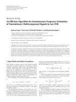
Figures 9 to 12 demonstrate the latency distribution
of the simulated methods. It shows that AFDSA has a
maximum latency for each traffic stream under its tolerable
latency (Table 3 ). In contrast, VBR traffic latency in HCCA
is uncontrollable and in EDCA exceeds the limit. Maximum
VBR latency for the proposed method is 80 milliseconds
but for FHCF is 50 milliseconds. This might seem to be an
advantage for FHCF but it must be considered that FHCF
is a centralized method that needs PC where AFDSA is a
distributed algorithm that does not need any PC. Also the
AFDSA latency is still lower than the tolerable latency for
VBR video. These differences relate to the starting situations.
FHCF starts with the SI
= 50 ms and continues by this yet
AFDSA starts with the SI
= 100 ms and then changes it
to 50 ms. So, the grater SI belongs to the starting TS, that
is, a VBR video stream which its maximum latency is 100.
VBR, CBR video and audio flows latency
0
20
40
60
80
100
120
Cummulative % of pkts
0 20 40 60 80 100 120 140 160
Latency (ms)
Audio
VBR Video
CBR Video
Figure 9: Latency distribution for FHCF.
VBR, CBR video and audio flows latency
0
20
40
60
80
100
120
Cummulative % of pkts
0 200 400 600 800 1000 1200 1400
Latency (ms)
Audio
VBR Video
CBR Video
Figure 10: Latency distribution for standard HCF.
Therefore, AFDSA sets the currentSI to 100 then it changes it
to 50.
The same figure also shows that the latency distribution
curve of the VBR flow has a stair shape. This shape relates
to the packets interarrival time. Analysis of the VBR video
trace file shows that the interarrival time of packets is 34
milliseconds (see Ta ble 2 ) but some packets are received
Saeid Montazeri et al. 9
VBR, CBR video and audio flows latency
0
20
40
60
80
100
120
Cummulative % of pkts
0 20 40 60 80 100 120 140 160 180
Latency (ms)
Audio
VBR Video
CBR Video
Figure 11: Latency distribution for AFDSA.
VBR, CBR video and audio flows latency
0
20
40
60
80
100
120
Cummulative % of pkts
0 20 40 60 80 100 120 140 160 180 200
Latency (ms)
Audio
VBR Video
CBR Video
Figure 12: Latency distribution for EDCA.
simultaneously so the mean arrival time is 26 milliseconds.
With 34 milliseconds interarrival time, the arrival times
repeat with a period near 400ms. Therefore, packets can
only get some specific latency between 0 and 50 milliseconds
which causes a stair-shape latency distribution curve.
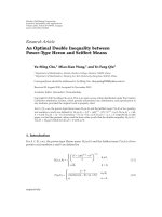
Figures 13 to 16 show the latency during the time. As
depicted in these figures, the latency of AFDSA and FHCF
methods are better than others. HCCA has problem in
VBR video traffic and EDCA has problem with CBR video.
Also the jitter of different flows in different methods is
summarized in Ta b le 5. Although EDCA has very low jitter, it
suffers from very high-dropped packet number as illustrated
in Ta ble 6 .
Ta ble 3 demonstrates the characteristics of the selected
traffics. The different VBR flows have been obtained with
VBR, CBR video and audio flows latency
0
50
100
150
200
Latency (ms)
02 4 6 8101214161820
Time (s)
Audio (mean lat
= 20.013 ms,
latency std. dev
= 14.5ms)
VBR video (mean lat
= 22.289 ms,
latency std. dev
= 14.729 ms)
CBR video (mean lat
= 23.483 ms,
latency std. dev= 15.137 ms)
Figure 13: FHCF latency.
Table 6: Dropped-packet number for different methods.
HCCA FHCF AFDSA EDCA
Audio 0 0 0 0
VBR Video 0 0 0 0
CBR Video 108 91 101 6794
VIC video-conferencing tool using the H.261 coding and
QCIF format for typical “head and shoulder” video
sequence. The PHY and MAC layer parameters used in the
simulation are also summarized in Tabl e 4.
There are two methods to increase the channel load:
increasing the node number and increasing the packet size.
The latter is selected for increasing the channel load in this
simulation. It is a time-consuming method because CBR
video packets need more time to be transmitted. The packet
size of CBR MPEG4 video has been increased from 600 to
1000 bytes to achieve 96% channel load.
Figure 17 shows fairness for VBR and CBR video traffic
streams when the load increases up to 96%. In order to
compare the fairness of the different schemes for the same
kind of traffic, Jain’s fairness index has been employed [18]:
J
=
n
i
=1
d
i
2
n
n
i
=1
d
2
i
, (12)
where d
i
is the mean delay of the flow i and n is the number
of flows. Figure 17 indicates that FHCF and AFDSA are fairer
than HCCA.
4.2. Scenario 2
In scenario 2 (see Ta ble 5 ), there are 7 nodes, six of which
are sources and another is destination. Each QSTA has three
10 EURASIP Journal on Advances in Signal Processing
VBR, CBR video and audio flows latency
0
200
400
600
800
1000
1200
1400
1600
Latency (ms)
02 4 6 8101214161820
Time (s)
Audio (mean lat
= 19.222 ms,
dev
= 14.253 ms)
VBR video (mean lat
= 598.7ms,
dev
= 460.575 ms)
CBR video (mean lat
= 66.071 ms,
dev= 20.057 ms)
Figure 14: HCCA latency.
VBR, CBR video and audio flows latency
0
50
100
150
200
Latency (ms)
02 4 6 8101214161820
Time (s)
Audio (mean lat
= 24.763 ms,
latency std. dev
= 14.169 ms)
VBR video (mean lat
= 39.044 ms,
latency std. dev
= 19.411 ms)
CBR video (mean lat
= 28.452 ms,
latency std. dev= 13.758 ms)
Figure 15: AFDSA latency.
different traffic flows (audio, VBR H.261 video, and CBR
MPEG4 video flows) simultaneously through three different
MAC layer priority classes. We increase the channel load by
increasing the packet size of CBR MPEG4 traffic from 600
bytes (2.4 Mbps) to 1000 bytes (4 Mbps) using a 100 bytes
increment and keeping the same interarrival period of 2
milliseconds.
VBR, CBR video and audio flows latency
0
50
100
150
200
Latency (ms)
0 2 4 6 8 10 12 14 16 18 20
Time (s)
Audio (mean lat
= 0.881 ms,
latency std. dev
= 0.923 ms)
VBR video (mean lat
= 3.848 ms,
latency std. dev
= 3.247 ms)
CBR video (mean lat
= 94.4ms,
latency std. dev= 22.536 ms)
Figure 16: EDCA latency.
Mean fairness of the VBR flows versus channel load
0.6
0.7
0.8
0.9
1
Jain’s fairness index
68 71 82.589.595
Channel load (%)
AFDSA
FHCF
HCCA
(a)
Mean fairness of the CBR video flows versus channel load
0.93
0.94
0.95
0.96
0.97
0.98
0.99
1
Jain’s fairness index
68 71 82.589.595
Channel load (%)
AFDSA
FHCF
HCCA
(b)
Figure 17: Mean fairness for VBR and CBR flows.
Saeid Montazeri et al. 11
Mean delay of the audio flows versus channel load
0
8
16
24
32
Delay (ms)
68 71 82.589.595
Channel load (%)
AFDSA
FHCF
HCF
EDCA
(a)
Mean delay of the VBR flows versus channel load
0
100
200
300
Delay (ms)
68 71 82.589.595
Channel load (%)
AFDSA
FHCF
HCF
EDCA
(b)
Mean delay of the CBR flows versus channel load
0
20
40
60
80
100
120
140
Delay (ms)
68 71 82.589.595
Channel load (%)
AFDSA
FHCF
HCF
EDCA
(c)
Figure 18: Mean latency for different flows versus channel load.
Figures 18 and 19 show the mean delay and fairness of
several types of flows, obtained with the various schemes, for
different loads of network, respectively.
Audio and VBR H.261 video flows
Figure 18 shows that the delay is almost constant for the
FHCF and the AFDSA with increase in the load which
indicates that delay does not strongly depend on the network
load.InHCCA,VBRtraffic has a high value of delay (300
milliseconds) that exceeds the limit for this kind of traffic.
In EDCA, mean latency is very low for audio and VBR
video traffic streams because of the high priority that had
been assigned for these streams. This increases the delay of
CBR video traffic and it linearly increases with increase in
trafficload.Figure 19 shows Jain index for all four methods.
These methods are almost similar for audio traffic. It is
Mean fairness of the audio flows versus channel load
0.96
0.97
0.98
0.99
1
Jain’s fairness index
68 71 82.589.595
Channel load (%)
AFDSA
FHCF
HCF
EDCA
(a)
Mean fairness of the VBR flows versus channel load
0.6
0.7
0.8
0.9
1
Jain’s fairness index
68 71 82.589.595
Channel load (%)
AFDSA
FHCF
HCF
EDCA
(b)
Mean fairness of the CBR video flows versus channel load
0.93
0.94
0.95
0.96
0.97
0.98
0.99
1
Jain’s fairness index
68 71 82.589.595
Channel load (%)
AFDSA
FHCF
HCF
EDCA
(c)
Figure 19: Mean fairness of different flows versus channel load.
apparent that AFDSA and FHCF are better than EDCA and
HCCA for VBR video traffic.
CBR MPEG4 video flows
In our simulation, CBR streams are responsible for increas-
ing the traffic load. As we can see in Figure 18,latencyis
almost constant for HCCA, FHCF, and AFDSA but increases
with the load increment for EDCA such that for loads more
than 79% it exceeds the limit for CBR traffic (100 ms).
Figure 19 shows that Jain’s index for all methods is high with
minor differences for CBR video traffic.
5. CONCLUSION
A new distributed MAC scheduling algorithm (AFDSA)
for upcoming 802.11e standard is proposed and evaluated.
12 EURASIP Journal on Advances in Signal Processing
The mechanism introduces three additional fields to the
RTS/CTS frame to guarantee QoS. The EDCA method of
802.11e is used to access the channel for the first time. When
time duration is reserved for a station, the rest of the stations
only compete for accessing the channel in the unreserved
periods. It is shown through extensive simulation that the
AFDSA can guarantee QoS for both CBR and VBR video
traffic. It does not need any point coordinator and each
node can play an access point role if it is connected to the
backbone.
REFERENCES
[1] IEEE 802.11 WG, “IEEE std. 802.11e, Part 11: Wireless
MAC and physical layer specifications: MAC Quality of
Service Enhancements,” Reference number ISO/IEC 15802-3,
November 2005.
[2] M. Malli, Q. Ni, T. Turletti, and C. Barakat, “Adaptive fair
channel allocation for QoS enhancement in IEEE 802.11
wireless LANs,” in Proceedings of IEEE International Conference
on Communications (ICC ’04), vol. 6, pp. 3470–3475, Paris,
France, June 2004.
[3] J. Zhao, Z. Guo, Q. Zhang, and W. Zhu, “Distributed MAC
adaptation for WLAN QoS diffrerentiation,” in Proceedings
of IEEE Global Telecommunications Conference (GLOBE-
COM ’03), vol. 6, pp. 3442–3446, San Francisco, Calif, USA,
December 2003.
[4] L. Romdhani, Q. Ni, and T. Turletti, “Adaptive EDCF:
enhanced service differentiation for IEEE 802.11 wireless ad
hoc networks,” in Proceedings of IEEE Wireless Communica-
tions and Networking Conference (WCNC ’03), vol. 2, pp.
1373–1378, New Orleans, La, USA, March 2003.
[5] G. W. Wong and R. W. Donaldson, “Improving the QoS
performance of EDCF in IEEE 802.11e wireless LANs,” in Pro-
ceedings of IEEE Pacific RIM Conference on Communications,
Computers, and Signal Processing (PACRIM ’03), vol. 1, pp.
392–396, Victoria, Canada, August 2003.
[6] W. Pattara-Atikom, S. Banerjee, and P. Krishnamurthy, “A-
DRAFT: an adaptive QoS mechanism to support absolute and
relative throughput in 802.11 wireless LANs,” in Proceedings of
the 7th ACM Symposium on Modeling, Analysis and Simulation
of Wireless and Mobile Systems (MSWiM ’04), pp. 117–125,
Venezia, Italy, October 2004.
[7] J. F. Lee, W. Liao, and M. C. Chen, “A MAC-layer differentiated
service model in IEEE 802.11e WLANs,” in Proceedings of IEEE
Global Telecommunications Conference (GLOBECOM ’05), vol.
6, pp. 3290–3294, St. Louis, Mo, USA, November-December
2005.
[8] Q. Deng and A. Cai, “A TXOP-based scheduling algorithm for
video transmission in IEEE 802.11e networks,” in Proceedings
of the 6th International Conference on ITS Telecommunications
(ITST ’06), pp. 573–576, Chengdu, China, June 2006.
[9] C. Liu and C. Zhou, “Providing quality of service in IEEE
802.11 WLAN,” in Proceedings of the 20th IEEE International
Conference on Advanced Information Networking and Applica-
tions (AINA ’06), vol. 1, pp. 817–822, Vienna, Austria, April
2006.
[10] E C. Park, D Y. Kim, C H. Choi, and J. So, “Improving
quality of service and assuring fairness in WLAN access
networks,” IEEE Transactions on Mobile Computing, vol. 6, no.
4, pp. 337–350, 2007.
[11] J. Jackson Juliet Roy, V. Vaidehi, and S. Srikanth, “A QoS
weight based multimedia uplink scheduler for IEEE 802.11e
WLAN,” in Proceedings of the International Conference on Sig-
nal Processing Communications and Networking (ICSCN ’07),
pp. 446–451, Chennai, India, February 2007.
[12] P. Ansel, Q. Ni, and T. Turletti, “FHCF: a simple and efficient
scheduling scheme for IEEE 802.11e wireless LAN,” Mobile
Networks and Applications, vol. 11, no. 3, pp. 391–403, 2006.
[13] A. Grilo, M. Macedo, and M. Nunes, “A scheduling algorithm
for QoS support in IEEE802.11E networks,” IEEE Wireless
Communications, vol. 10, no. 3, pp. 36–43, 2003.
[14] G. Boggia, P. Camarda, L. A. Grieco, and S. Mascolo,
“Feedback-based bandwidth allocation with call admission
control for providing delay guarantees in IEEE 802.11e
networks,” Computer Communications, vol. 28, no. 3, pp. 325–
337, 2005.
[15] B. A. Venkatakrishnan and S. Selvakennedy, “An enhanced
HCF for IEEE 802.11e wireless networks,” in Proceedings of
the 7th ACM Symposium on Modeling, Analysis and Simulation
of Wireless and Mobile Systems (MSWiM ’04), pp. 135–142,
Venezia, Italy, October 2004.
[16] S. Montazeri, R. Berangi, and M. Fathy, “A new distributed
scheduling algorithm to guarantee QoS parameters for
802.11e WLAN,” in Proceedings of the International Conference
on Information Networking (ICOIN ’06), vol. 3961 of Lecture
Notes in Computer Science, pp. 132–145, Sendai, Japan,
January 2006.
[17] P. M. Soni and A. Chockalingam, “Performance analysis
of UDP with energy efficient link layer on Markov fading
channels,” IEEE Transactions on Wireless Communications, vol.
1, no. 4, pp. 769–780, 2002.
[18] R. Jain, The Art of Computer Systems Performance Analysis,
John Wiley & Sons, New York, NY, USA, 1991.