Báo cáo hóa học: "Research Article Multiuser Detection Using Adaptive Multistage Matrix Wiener Filtering Schemes with Stage-Selection Criteria in DS-UWB" docx
Bạn đang xem bản rút gọn của tài liệu. Xem và tải ngay bản đầy đủ của tài liệu tại đây (826.55 KB, 9 trang )
Hindawi Publishing Corporation
EURASIP Journal on Advances in Signal Processing
Volume 2008, Article ID 426807, 9 pages
doi:10.1155/2008/426807
Research Article
Multiuser Detection Using Adaptive M ultistage Matrix Wiener
Filtering Schemes with Stage-Selection Criteria in DS-UWB
Chia-Chang Hu
1
and Hsuan-Yu Lin
2
1
Department of Communications Engineering, National Chung Cheng University, Min-Hsiung, Chia-Yi 621, Taiwan
2
Telecom Technology Division, Telecom Technology Center, Lujhu, Kaohsiung 821, Taiwan
Correspondence should be addressed to Chia-Chang Hu,
Received 13 November 2007; Revised 11 June 2008; Accepted 10 September 2008
Recommended by Arden Huang
Adaptive reduced-rank (RR) multistage matrix Wiener filtering (MMWF) techniques, based on the minimum mean-square error
(MMSE) criterion, are proposed for direct-sequence (DS) ultra-wideband (UWB) communication systems. These RR-MMWF-
based algorithms employ an adaptive fuzzy-inference determined filter stage. As a consequence, the proposed schemes achieve
a substantial saving in complexity without compromising system performance and dynamic convergence/tracking capability.
Additionally, the fuzzy-logic-controlled matrix conjugate gradient (MCG) algorithm is developed for a robust and reduced-rank
implementation of the full-rank MMWF. Simulations are conducted to illustrate the convergence/tracking superiority and to
provide a comparative evaluation of the proposed algorithms with the MMWF-based schemes using other adaptive stage-selecting
criteria.
Copyright © 2008 C C. Hu and H Y. Lin. This is an open access article distributed under the Creative Commons Attribution
License, which permits unrestricted use, distribution, and reproduction in any medium, provided the original work is properly
cited.
1. INTRODUCTION
Ultra-wideband (UWB) systems have drawn considerable
attention as an indoor short-range high-data-rate transmis-
sion in wireless communications over the past few years.
Equalization of the UWB signals [1, 2] based on the con-
ventional RAKE receiver technique has been addressed for
both additive white Gaussian noise (AWGN) and multipath
rich channels [3–11]. However, the RAKE reception suffers
from its multiple-access interference (MAI) suppression
capability. It is well known that the linear minimum mean-
squareerror(MMSE)receiver[12] is capable to suppress
the MAI efficiently. In [13, 14], the MMSE-based detectors
are proposed for direct-sequence (DS) UWB communication
systems. Moreover, it is shown that the MMSE decision-
feedback detection (DFD) receiver is able to provide a better
performance than the MMSE receiver alone even when the
error propagation occurs [15]. The MMSE-DFD usually
consists of one MMSE receiver in the forward path and
one feedback filter in structure. Unfortunately, the com-
putation of the MMSE-based filter weights starts with the
calculation of the inverse of the input signal autocorrelation
matrix, which involves an expensive computational cost. This
requirement is even more exacerbated when the MMSE-
based receiver operates in a nonstationary environment.
To alleviate computational complexity, the authors in [16–
20] propose a considerably lower complexity version of the
MMSE receiver that utilizes the reduced-rank multistage vec-
tor Wiener filter (MVWF). This MVWF technique obviates
the necessity of either a covariance matrix inversion or an
eigen-decomposition. Additionally, there exist other iterative
matrix inversion techniques, among which the conjugate
gradient (CG) [21] scheme is able to provide fast initial
convergence of the iterative procedure. It can also be shown
that the CG scheme as well as the MVWF technique produces
an MMSE approximation in the same Krylov subspace [22].
In this paper, an adaptive fuzzy-inference (FI) multistage
matrix Wiener filtering (MMWF) technique, based on the
MMSE performance criterion, is proposed to detect DS-
UWB signals. A reduced-rank DFD scheme based on the
MMWF is also considered. The MMWF, which can be com-
pared analogously to the MVWF, is introduced to implement
the MMWF-DFD receiver without a direct matrix inversion
or eigen-decomposition. The feedforward and feedback
filters of the MMWF-DFD receiver are capable of sharing
the same calculation basis to alleviate the computational
2 EURASIP Journal on Advances in Signal Processing
burden without affecting system performance. Moreover, the
reduced-rank MMWF-based receivers [23]provideasig-
nificant performance gain and rapid adaptive convergence,
relative to the conventional full-rank MMSE-based receivers,
when observation-data support is limited [24]. In addition,
the matrix conjugate gradient (MCG) algorithm [25]is
developed for a robust implementation of the full-rank
MMWF. It should be pointed out that the filter-stage selec-
tion of the MMSE-based detectors governs the steady-state
performance and the convergence characteristic. In general,
a small-stage leads to rapid convergence but results in large
steady-state MSE. The opposite phenomena occur when a
large stage is chosen. To achieve better convergence/tracking
capability and steady-state MSE performance of the MMWF-
based receivers, we propose a fuzzy-inference controlled
stage-selection mechanism in this paper. It can be shown
that the fuzzy-inference system (FIS) [26]offers an effective
and robust means to monitor instantaneous fluctuations of
a dense multipath channel and thus is able to assist the
MMWF-based receivers in selecting a proper time-varying
filter stage M.
The rest of the paper is organized as follows. Section 2
describes the channel and system model. Sections 3 and
4 present the reduced-rank MMWF and the MMWF-DFD
schemes, respectively. The reduced-rank MCG scheme is
developed in Section 5. The details of the fuzzy-inference
controlled filter-stage selection mechanism are given in
Section 6. Section 7 analyzes the computational complex-
ity of the proposed mechanism. Section 8 describes three
existing filter stage-selection criteria. Numerical results and
conclusions are presented in Sections 9 and 10,respectively.
Symbols for matrices (vectors) are denoted by boldface
upper/lower case letters. The subscripts (
·)
x
and (·)
[x/y]
represent the integer floor of x and the integer division
remainder operation of x/y, respectively. The superscripts
(
·)
and (·)
H
stand for transposition and Hermitian
transposition, respectively. E
{·} denotes the expected-value
operator.
|·| and · indicate, respectively, the absolute
value and the matrix/vector Frobenius norm. I is the identity
matrix. sgn denotes the sign operator. tr
{·} is the trace
of a matrix. Re(
·) denotes the real part. Finally, round[·]
indicates rounding to the nearest integer.
2. SIGNAL AND SYSTEM MODEL
In a K-user DS-UWB communication system with the use of
BPSK modulation, the transmitted signal from user k can be
expressed as follows [27–30]:
x
k
(t) =
+∞
n=−∞
E
k
b
kn/N
c
c
k[n/N
c
]
p
t −nT
c
,(1)
where E
k
denotes the kth user’s energy per pulse at the
transmitter end and p(t) is the short-duration UWB pulse
with unit energy [1]. b
kn/N
c
∈{±1} denotes the n/N
c
th
BPSK modulated data symbol of duration T
s
.Eachsymbol
interval consists of N
c
transmission chips of duration T
c
,
that is, T
s
= N
c
T
c
. The pseudorandom code of length N
c
,
{c
k[n/N
c
]
}, denotes the normalized spreading code sequence
of the kth user, where c
k[n/N
c
]
takes the value of −1/
N
c
or
+1/
N
c
with equal probability.
The UWB multipath channel of user k can be described
by its complex impulse response [6, 31–34]:
h
k
(t) =
J
k
−1
j=0
α
kj
δ
t −τ
kj
,(2)
where J
k
is the number of resolvable multipaths of user k.
α
kj
indicates the complex multipath gain coefficient and τ
kj
is the propagation delay, which are associated with the jth
path of user k. The probability distribution of α
kj
is given
by N(0, (1/2)σ
2
kj
)+jN(0, (1/2)σ
2
kj
), where N(0, (1/2)σ
2
kj
)isa
zero-mean Gaussian random variable with variance (1/2)σ
2
kj
,
j
= 0, 1, , J
k
−1. The energy of the jth channel path of user
k, σ
2
kj
,isgivenby
σ
2
kj
= σ
2
0
e
−l
kj
T
c
/τ
RMS
,(3)
where σ
2
0
is chosen to ensure that the average received energy
is unity and τ
RMS
denotes the RMS delay spread. In addition,
a chip-synchronous DS-UWB system is considered with
τ
kj
= l
kj
T
c
,wherel
kj
∈ [0, J
k
−1] is selected randomly. In this
paper, the parameters of CM4 [35] are used to generate the
energy of each channel tap for the non-line-of-sight (NLOS)
multipath channel.
After multipath fading channel “processing,” the total
received signal at the receiver is a superposition of propa-
gated signals from all K users and the background channel
noise. The received signal r(t)canbewrittenas
r(t)
=
K
k=1
E
k
J
k
−1
j=0
α
kj
×
+∞
n=−∞
b
kn/N
c
c
k[n/N
c
]
p
t −nT
c
−τ
kj
+ n(t),
(4)
where n(t) indicates an AWGN.
3. REDUCED-RANK MMWF SCHEME
The received signal r(t)in(4) is passed through the chip-
matched filter and is then sampled at the chip-rate over
the multipath extended (N
c
+ J
k
− 1)-chip period [36]. For
simplicity of notation, let N stand for the number of (N
c
+
J
k
−1) in what follows. Denote by
r(i)
=
r
1
(i), r
2
(i), , r
N
(i)
(5)
the column N-vector of the discrete-time received samples
corresponding to the ith information symbol interval. For
the purpose of analysis, the desired users, Users 1
∼J,are
assumed to be perfectly synchronized at the receiver [36].
Let b(i)
= [b
1
(i), b
2
(i), , b
J
(i)]
be the desired data J-
vector and R
rb
Δ
= E{r(i)b
H
(i)} denote the corresponding
steering matrix. The MMSE receiver is the N
× J matrix W,
which is chosen to minimize the MSE, that is, MSE(W)
Δ
=
E{b(i) −W
H
r(i)
2
}. The weight matrix W is given by
W
MMSE
= arg min
W
MSE(W) = R
−1
rr
R
rb
,(6)
C C. Hu and H Y. Lin 3
where R
rr
Δ
= E{r(i)r
H
(i)}. Evidently, the computation of
matrix W
MMSE
in (6) requires the inversion of matrix R
rr
.To
avoid the computation of R
−1
rr
, the MMWF is used to perform
decompositions of the observation vector by utilizing a series
of orthogonal projections. Define the nonsingular linear
transformation T
1
with the structure [37]
T
1
=
U
H
1
B
1
=
R
H
rb
B
1
,(7)
where U
1
= R
rb
is an N ×J matrix and B
1
is an (N −J) ×N
blocking matrix with B
1
U
1
= 0. Hence, the transformation
of the vector r(i) by the operator T
1
in (7)yieldsavectorz
1
(i)
in the form
z
1
(i) = T
1
r(i) =
U
H
1
r(i)
B
1
r(i)
=
b
1
(i)
r
1
(i)
,(8)
where b
1
(i) = U
H
1
r(i)andr
1
(i) = B
1
r(i). Subsequently, the
correlation matrix of z
1
(i), R
z
1
z
1
, and its inverse R
−1
z
1
z
1
can be
computed as
R
z
1
z
1
= T
1
R
rr
T
H
1
=
R
b
1
b
1
R
H
r
1
b
1
R
r
1
b
1
R
r
1
r
1
,
R
−1
z
1
z
1
=
00
0R
−1
r
1
r
1
+
I
−R
−1
r
1
r
1
R
r
1
b
1
Σ
−1
1
I −R
H
r
1
b
1
R
−1
r
1
r
1
,
(9)
where the J
× J covariance matrix Σ
1
of error, e
1
= b
1
(i) −
(R
−1
r
1
r
1
R
r
1
b
1
)
H
r
1
(i), is given by
Σ
1
= E
e
1
e
H
1
= R
b
1
b
1
−R
H
r
1
b
1
R
−1
r
1
r
1
R
r
1
b
1
. (10)
Consequently, the linear MMSE receiver of (6)canbere-
expressed in the form
W
MMSE
= T
H
1
T
1
R
rr
T
H
1
−1
T
1
R
rb
(11)
=
R
rb
−B
H
1
R
−1
r
1
r
1
R
r
1
b
1
Σ
−1
1
Δ
1
=
U
1
−B
H
1
W
1
Υ
1
,
(12)
where Δ
1
= U
H
1
U
1
, W
1
= R
−1
r
1
r
1
R
r
1
b
1
,andΥ
1
= Σ
−1
1
Δ
1
.The
first-stage (M
= 1) orthogonal decomposition process of
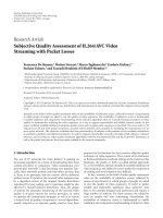
the MMWF receiver in (12)isillustratedinFigure 1.Sub-
sequently, the decomposition procedure applied to W
MMSE
in (11) is used to W
1
and continued until the minimum
dimension of both the data vector and the corresponding
Wiener filter are achieved. Evidently, the maximum number
of stages in the MMWF receiver is defined by M
MAX
=N/J.
This results in a set of recursion equations with the number
of stages M, as shown in Algorithm 1.Rankreductionis
realized by truncating the multistage decomposition process
at the Mth stage, where MJ
N (full rank). Thus, the stage-
M output, denoted by W
MMWF,M
(r(i)), can be obtained by
the following equation:
W
MMWF,M
(r(i)) = Υ
1
b
1
−···−Υ
M−1
b
M−1
−Υ
M
b
M
=
Υ
1
b
1
−···+(−1)
(M−1)
M
j=1
Υ
j
b
M
.
(13)
r(i)
U
1
b
1
−
+
e
1
γ
1
e
0
=
b
MMSE
B
H
1
r
1
W
1
W
MMSE
= R
−1
rr
R
rb
Figure 1: Block diagram of the first-stage orthogonal decomposi-
tion process of the MMWF receiver.
Initialization b
0
= b(i), r
0
= r(i), U
1
=
R
rb
, B
1
= null(U
1
).
Forward recursion
For j
= 1, 2, , M −1
b
j
= U
H
j
r
j−1
r
j
= B
j
r
j−1
Δ
j
= U
H
j
U
j
U
j+1
=
R
r
j
b
j
B
j+1
= null(U
j+1
)
End
Backward recursion
e
M
= b
M
= U
H
M
r
M−1
, Σ
M
=
R
e
M
e
M
=
R
b
M
b
M
,
and Υ
M
= Σ
−1
M
Δ
M
.
For j
= M − 1, M −2, ,1
e
j
= b
j
−Υ
H
j+1
e
j+1
Σ
j
=
R
b
j
b
j
−Δ
H
j+1
Σ
−1
j+1
Δ
j+1
Υ
j
= Σ
−1
j
Δ
j
End
Feedforward and feedback filters of the MMWF-DFD scheme
M-Stage MMWF Scheme
Q
≈ I − Δ
H
1
Σ
−1
1
Δ
1
D = diag ·[(Q
−1
)
11
,(Q
−1
)
22
, ,(Q
−1
)
JJ
]
B
= Q
−1
D
−1
−I
Data vector estimation
b
MMSE
= sgn(e
0
) = sgn(Υ
H
1
e
1
)
b
0
= sgn[(I + B)
H
e
0
−B
H
b
0
], (perfect feedback)
b
0
= sgn[(I + B)
H
e
0
−B
H
sgn(e
0
)], (imperfect feedback)
Algorithm 1: Recursion equations for the M-stage MMWF/
MMWF-DFD schemes.
4. REDUCED-RANK MMWF-DFD SCHEME
The MMSE-DFD receiver is known to be able to outperform
a linear MMSE detector. The MMSE-DFD usually consists of
one MMSE receiver in the forward path and one feedback
filter. The former is used for MAI suppression and the
latter is for self-interference cancellation. Here, the parallel
decision feedback detector (P-DFD) [38] based on the
MMSE criterion is considered for multiuser detection in the
DS-UWB communication systems. The feedforward filter of
the P-DFD consists of the linear MMSE filter followed by an
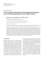
error estimation filter, as shown in Figure 2. Following the
4 EURASIP Journal on Advances in Signal Processing
derivation in [38], the feedforward and feedback filters of the
P-DFD receiver can be expressed, respectively, as
F
= W
MMSE
(I + B),
B
= Q
−1
D
−1
−I.
(14)
Here,
Q
Δ
= E
b(i) −W
H
MMSE
r(i)
b(i) −W
H
MMSE
r(i)
H
=
I −R
H
rb
R
−1
rr
R
rb
(15)
defines the J
×J error covariance matrix and the J ×J matrix
D
= diag ·[(Q
−1
)
11
, ,(Q
−1
)
JJ
] is adopted to normalize the
matrix Q
−1
. Note that the MMSE receiver in the forward
path, W
MMSE
, can be computed by the MMWF in a reduced-
rank form with the use of U
1
= R
rb
. Fortunately, the
feedback filter B
= (I − R
H
rb
R
−1
rr
R
rb
)
−1
D
−1
− I can be
computed efficiently by sharing the information from the
MMWF. Specifically, by applying T
1
to both sides of R
−1
rr
at
the first stage of decomposition, we have
R
H
rb
R
−1
rr
R
rb
= R
H
rb
T
H
1
T
1
R
rr
T
H
1
−1
T
1
R
rb
= Δ
H
1
Σ
−1
1
Δ
1
,
(16)
where
T
1
R
rb
=
Δ
1
0
. (17)
Consecutively, a sequence of T
2
, , T
M
is applied to perform
successive orthogonal decompositions of R
−1
r
1
r
1
, , R
−1
r
M−1
r
M−1
and neglecting the term of R
H
r
M
b
M
R
−1
r
M
r
M
R
r
M
b
M
, Σ
1
becomes
[39, 40]
Σ
1
= R
b
1
b
1
−R
H
r
1
b
1
T
H
2
T
2
R
r
1
r
1
T
H
2
−1
T
2
R
r
1
b
1
= R
b
1
b
1
−Δ
H
2
R
b
2
b
2
−R
H
r
2
b
2
R
−1
r
2
r
2
R
r
2
b
2
−1
Δ
2
≈ R
b
1
b
1
−Δ
H
2
R
b
2
b
2
−···
R
b
M−2
b
M−2
−Δ
H
M
−1
R
−1
b
M−1
b
M−1
×Δ
M−1
−1
···
−1
Δ
2
.
(18)
Therefore, the matrix Σ
1
in (18) can be utilized to estimate
Q in (15) as follows: Q
≈ I − Δ
H
1
Σ
−1
1
Δ
1
. Note that the
MMWF-DFD scheme eliminates the need for a large matrix
inversion, that is, R
−1
rr
, thus a substantial reduction of the
computational cost can be achieved from the MMSE-DFD
receiver. The set of recursion equations of the MMWF-
DFD scheme and the estimate of the desired data vector are
summarized in Algorithm 1.
5. REDUCED-RANK MCG SCHEME
The MCG algorithm can be applied to the common problem
that we encounter in adaptive transversal filters. In other
words, this algorithm is ideally suitable for deriving the
solution of linear equations of a system, such as
R
rr
W = R
rb
. (19)
r(i)
−
+
e
0
b
Linear MMSE
filter
W
MMSE
= R
−1
rr
R
rb
Error
estimation
filter
I + B
Decision
Feedforward filter F
Feedback
filter
B
Figure 2: Block diagram of the MMSE-DFD Receiver.
It is indirectly minimizing a cost function ξ defined as
ξ(W)
= tr
R
bb
−2Re
R
H
rb
W
+ W
H
R
rr
W
. (20)
Note that the method of CG is simply the method of
conjugate directions [41] where the search directions are
constructed by conjugation of the residuals. In addition,
it is worth to emphasize that the CG scheme cures the
problem that the steepest descent (SD) method often finds
itself taking steps in the same direction as earlier steps. In the
CG algorithm, a set of R
rr
-orthogonal, or conjugate, search
directions are picked and exactly only one step is taken in
each search direction. Moreover, the difficulty is overcome by
the CG method with using the Gram-Schmidt conjugation
in the method of conjugate directions that all the old search
vectors need to be kept in memory to construct each new
one.
It is readily shown that the minimum MSE can be written
as
ξ
W
MMSE
=
tr
R
bb
−R
H
rb
R
rr
R
rb
. (21)
The MCG algorithm for implementing the MMWF starts
with the initial matrix W
MCG,0
, the initial search direction
matrix D
0
, and the initial residual matrix G
0
= D
0
= R
rb
−
R
rr
W
MCG,0
. The MCG algorithm updates the filter matrix at
the (j +1)thiterationasfollows:
W
MCG,j+1
= W
MCG,j
+ D
j
V
j
, (22)
where the step matrix is given by
V
j
=
D
H
j
R
rr
D
j
−1
G
H
j
G
j
. (23)
The residual matrix is calculated according to the equation
given by
G
j+1
= G
j
−R
rr
D
j
V
j
. (24)
The R
rr
-conjugate direction matrix is updated as follows:
D
j+1
= G
j+1
+ D
j
G
H
j
G
j
−1
G
H
j+1
G
j+1
. (25)
To sum up, the MCG algorithm is an iteration method for
solving the Wiener-Hopf equation in a finite number of
iterations. It can be shown that both the MCG and the
MMWF schemes produce an MMSE approximation in the
C C. Hu and H Y. Lin 5
Initialization: W
MCG,0
= 0
N×J
, D
0
= G
0
=
R
rb
−
R
rr
W
MCG,0
.
For j
= 1, 2, , M −1
V
j
= (D
H
j
R
rr
D
j
)
−1
G
H
j
G
j
,
W
MCG,j+1
= W
MCG,j
+ D
j
V
j
,
G
j+1
= G
j
−
R
rr
D
j
V
j
,
Γ
j+1
= (G
H
j
G
j
)
−1
G
H
j+1
G
j+1
,
D
j+1
= G
j+1
+ D
j
G
j+1
,
End
Algorithm 2: Recursion equations for the MCG scheme.
same Krylov subspace [22]. Additionally, both algorithms
are based on optimization with identical cost functions,
thus, computing the same approximate solution. The MCG
algorithm is guaranteed to converge in N steps and converges
more quickly when the eigenvalues of R
rr
are clustered
together. Furthermore, the MCG scheme does not need to
computeanestimateofR
−1
rr
. At every iteration step, the
algorithm provides an improved approximation for the exact
solution. Finally, the steps of the robust MCG algorithm
with a fuzzy-inference controlled M-iteration are listed in
Algorithm 2.
6. FUZZY-INFERENCE FILTER-STAGE SELECTION
The 2-to-1 fuzzy inference system (FIS) [26], based on the
principle of fuzzy logic [42], uses the squared error (e
2
(i))
and the squared error variation (Δe
2
(i)) as the input variables
at time i to assign the number of the filter-stage M(i+1).That
is,
M(i +1)
= FIS
e
2
(i), Δe
2
(i)
, (26)
where e
0
(i) = b(i) − W
H
MMWF/MCG,M
(i)r(i), e
2
(i) =
(e
H
0
(i)e
0
(i))/J,andΔe
2
(i) =|e
2
(i) − e
2
(i − 1)|. Notice that
b(i) = sgn(W
H
MMWF/MCG,M
(i)r(i)) is used to compute the
vector e
0
(i) in blind-mode algorithms. In essence, the basic
configuration of the FIS comprises four essential procedures,
namely, (i) fuzzy sets for parameters, (ii) fuzzy rules, (iii)
fuzzy operators, and (iv) defuzzification processes, which
map a two-input vector, (e
2
(i), Δe
2
(i)), into a single-output
parameter M for the adaptive time-varying stage selection.
The function of each procedure in the FIS is introduced
briefly as follows:
(1) Fuzzy sets for parameters: The input variables of the
FIS are transformed to the respective degrees to which they
belong to each of the appropriate fuzzy sets via membership
functions (MBFs). In what follows, the (e
2
, Δe
2
)-FIS system
with the (8, 4)-partitioned regions to the fuzzy I/O domains
[26] is employed, due to its excellent performance and
moderate complexity(eight-triangular MBFs with centroids
of the ultra-large (UL), very large (VL), large (L), medium
(M), small medium (SM), small (S), very small (VS), and
ultra-small (US), respectively, are selected to cover the entire
universe of discourse for variables e
2
and M.) Four-triangular
MBFs with centroids of the VL, L, M, and S, respectively,
are utilized for the variable Δe
2
in this paper. The output
of the fuzzification process demonstrates a fuzzy degree of
membership between 0 and 1.
(2) Fuzzy control rules: This procedure is focused on
constructing a set of fuzzy IF-THEN rules. Here, we claim
that the convergence is just at the beginning in case of a “UL”
e
2
and a “VL” Δe
2
and thus a “UL” value for M is used to
speed up its convergence rate. On the other hand, the filter
is assumed to operate in the steady-state status when e
2
is
“US” and Δe
2
shows “S,” and then a “US” M is adopted to
lower its steady-state MSE. In particular, we may declare that
a huge estimation error has occurred when e
2
is “US” and Δe
2
indicates “VL” and the “US” value of parameter M is assigned
to system in order to stabilize system performance.
(3) Fuzzy operators: The fuzzified input variables are
combined using the fuzzy “OR” operator, which selects
the maximum value of the two, to obtain a single value.
Subsequently, this is followed by the implication process,
which defines the reshaping task of the consequent (THEN-
part) of the fuzzy rule based on the antecedent (IF-part). A
min (minimum) operation is generally employed to truncate
the output fuzzy set for each rule. Since decisions are based
on the testing of all of the rules in an FIS, the rules need to
be combined in some manner in order to make a decision.
Aggregation is the process by which the fuzzy sets that
represent the outputs of each rule are combined into a single
fuzzy set. The input of the aggregation process is the list
of truncated output functions returned by the implication
process for each rule. The output of the aggregation process
is one fuzzy set for each output variable.
(4) Defuzzification processes: The defuzzification process
converts fuzzy control decision into nonfuzzy control signals.
These control signals are applied to adjust the variable of
M in order to improve convergence/tracking capability of
the receiver. The crisp, physical control command is com-
puted by the centroid-defuzzification method. The centroid-
defuzzification output M is calculated by [43]
M(i +1)
=
Υ
l
=1
M
(l)
(i) ·m
(l)
M
(l)
(i)
Υ
l
=1
m
(l)
M
(l)
(i)
, (27)
where Υ is the number of discrete samples of the output MBF,
M
(l)
(i) is the value at the location used in approximating the
area under the aggregated MBF, and m
(l)
(M
(l)
(i)) ∈ [0, 1]
indicates the MBF value at location M
(l)
(i). To reduce the
computational load in the centroid calculation, fewer points
Υ must be used. The calculation of M(i +1)in(27)returns
the center of the area under the aggregated MBFs.
7. COMPUTATIONAL COMPLEXITY ANALYSIS
For the real-time applicability, a computationally efficient
version of the M-stage MMWF scheme is derived and
summarized in Algorithm 3 with the use of the blocking
matrix B
j
= I − U
j
U
H
j
and the estimated cross-correlation
matrix
R
r
j
b
j
= (1 − μ)
R
r
j−1
b
j−1
+ r
j
b
H
j
.Thequantityof
μ
∈ (0, 1] is referred to as the forgetting factor. The
heavily computational operations of null(
·)andE{·} can
be avoided successfully. Thus, it can be easily evaluated
from Algorithm 3 that the M-stage MMWF receiver costs
6 EURASIP Journal on Advances in Signal Processing
Initialization: b
0
= b(i), r
0
= r(i), U
1
=
R
rb
.
Forward recursion
For j
= 1, 2, , M −1
b
j
= U
H
j
r
j−1
r
j
= r
j−1
−U
j
b
j
Δ
j
= U
H
j
U
j
U
j+1
=
R
r
j
b
j
= (1 −μ)
R
r
j−1
b
j−1
+ r
j
b
H
j
End
Backward recursion
e
M
= b
M
= U
H
M
r
M−1
, Σ
M
=
R
e
M
e
M
=
R
b
M
b
M
,
and Υ
M
= Σ
−1
M
Δ
M
.
For j
= M − 1, M −2, ,1
e
j
= b
j
−Υ
H
j+1
e
j+1
Σ
j
=
R
b
j
b
j
−Δ
H
j+1
Σ
−1
j+1
Δ
j+1
Υ
j
= Σ
−1
j
Δ
j
End
Algorithm 3: Recursion equations for the simplified M-stage
MMWF scheme
a complexity of O(J
2
MN). Here, the big O(·)(orderof)
notation is used to indicate that complexity in number of
operations is proportional to the argument. The complexity
of the feedback filter of the MMWF-DFD scheme is at most
O(J
3
) (i.e., the computation of matrix Δ
H
1
Σ
−1
1
Δ
1
), which
is relatively small while compared to that of the MMWF
scheme. Consequently, the computational complexity of the
MMWF/MMWF-DFD systems is reduced substantially from
O(N
3
)toO(J
2
MN) for each computing cycle of clock time,
where J
2
M N
2
.
The primary complexity cost of the M-iteration MCG
algorithm in Algorithm 2 is the calculation of the step
matrix V
j
,whichinvolvesO(JN
2
)+O(J
3
)+O(J
2
N) ≈
O(JN
2
) of complexity per iteration. The computational
complexities of the W
MCG,j+1
, G
j+1
, Γ
j+1
,andD
j+1
,in
terms of multiplications can be easily shown to be equal to
O(J
2
N), O(JN
2
), O(J
3
)+O(JN
2
) ≈ O(JN
2
), and O(J
2
N)
per iteration, respectively. Hence, the M-iteration MCG
algorithm costs roughly O(JMN
2
) of complexity.
The additional computational load introduced by the
(2-to-1)-FIS, in terms of multiplications, is I + J +3at
each sample time, in which the preparation of e
2
(i)requires
J + 2 multiplications and the centroid-defuzzification output
process costs I+1 multiplications. Furthermore, some special
instructions (with a total of 44 lookups + 32 compares +
32I MAX operations) are required to perform the FIS, which
come primarily from the fuzzification of two input variables
(12 lookups), fuzzy OR operations (32 compares), fuzzy
minimum implication (32 lookups), and aggregation of the
output (32I MAX operations). Fortunately, these operations
canbedoneveryefficiently in the latest range of DSPs, which
provide single cycle multiply and add, table lookups, and
comparison instructions [44, 45].
8. EXISTING STAGE-SELECTION CRITERIA
In this section, three filter-stage adaptation schemes used in
[22, 24] are briefly reviewed. The first stage-selection method
is introduced originally in [46] for the rank-selection of an
auxiliary-vector (AV) estimator. The time-varying stage-M
of the AV filter is determined by the stopping rule,givenby
M(i)
= max
n :
P
⊥
S
n
(v
n
)
v
n
>η
, (28)
where P
⊥
S
(x) is the orthogonal projection of the vector x onto
the subspace S and the small positive constant η is computed
by (37) in [24]. Note that the subspace S
m
denotes the Krylov
space spanned by the basis vectors v
1
, v
2
, , v
m
,wherev
i
=
Ve c {R
i−1
rr
R
rb
}.
The second stage-selection technique for determining
the filter stage is based on minimizing the cumulative
exponentially-weighted squared error ξ, which is also know
as the a posteriori LS method, given by
ξ
M
(i) =
i
m=1
μ
i−m
b(m) −W
M
r(m)
2
, (29)
where (
·)
M
denotes the dynamic filter-stage at time i.For
each i, the value of M is chosen to minimize ξ
M
(i)defined
in (29).
The third stage-selection scheme is the well-known white
noise gain constraint (WNGC) [22] technique where the
filter-vector norm
w is utilized as a rank-selection tool.
The criterion used for the rank selection of the WNGC is
10 log
w
2
≤ 1 dB in this paper.
9. NUMERICAL RESULTS
A DS-UWB communication system with K
= 20 is
considered in multipath fading channels. Parameters N
c
=
310 and J
k
= 100 are used in computer simulations. In
simulations, users 1 to 5 are the users of interest to be
acquired, that is, J
= 5. Additionally, the (e
2
, Δe
2
)-FIS
system with the (8, 4)-partitioned regions to the fuzzy I/O
domains [26]isemployedduetoitssuperiorperformance.
The threshold level of the WNGC is selected as 1 dB in
simulations. All experimental curves are obtained using 10
3
independent trials with the use of μ = 0.99 and η = 0.01.
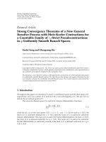
Figure 3 compares the convergence rate of various
reduced-rank MMWF-based algorithms with the use of
training symbols for SNR
= 20 dB. Results of dynamic-
stage MMWF algorithms using adaptation criteria of (28)
and (29)(i.e.,[24, equations (73) and (75)]) and WNGC are
provided and compared. It is demonstrated in the figure that
with the use of a small-stage (M
= 2), the MMWF algorithm
produces a faster convergence rate, while using a large-stage
(M
= 8) accomplishes a lower steady-state MSE. Thus, the
proposed FI-MMWF algorithm, which performs the fuzzy-
logic filter-stage selection over the range of [2, 8], takes
advantage of both small and large stages in convergence and
steady-state characteristic. Note that the extra computational
load incurred by both stage-selection criteria in [24] is heavy,
especially in the a posteriori LS method.
Figure 4 evaluates the convergence behavior of various
blind-mode reduced-rank MMWF-based algorithms. The
blind FI-MMWF-based algorithms can be obtained by
C C. Hu and H Y. Lin 7
10
−2
10
−1
10
0
Mean square error (MSE)
0 50 100 150 200 250 300 350 400
Numbers of iterations
MMWF (M
= 2)
MMWF (M
= 8)
FI-MMWF
MMWF using (28)
MMWF using (29)
MMWF using WNGC
Figure 3: Mean square error versus the number of training symbols
for reduced-rank MMWF-based algorithms.
simply substituting R
rb
by
R
rb
(“spreading” code matrix
of the desired users). The filter-stage selection of the FI-
MMWF-based algorithms is conducted over the set of [2, 5].
Experimental results in Figure 4 are similar to those of in
Figure 3. It should be pointed out that the convergence rate
of the low-stage MMWF is much faster than that of the high-
stage MMWF-based in the blind version. Consequently, the
advantage of fuzzy-stage selection MMWF-based algorithms
in blind version is quite impressive.
Simulation results in Figure 5 show the convergence
behavior of the blind-mode FI-MCG algorithm in terms
of the number of iterations. Other parameters used in
Figure 5 are set as in Figure 4. Evidently, the FI-MCG
algorithm produces better convergence/tracking capability
and steady-state MSE performance than MMWF schemes
with a fixed stage. Additionally, the results in Figure 5
demonstrate that an improvement in MSE performance over
the MCG scheme is achieved by the FI-MCG algorithm,
presumably because of the use of a fuzzy variable stage in
response to the time-varying fading channels. Also, these
results show that the FI-MCG algorithm is able to accomplish
a similar performance as the FI-MMWF-based approaches.
Results in Figure 5 provide the convergence behavior of the
MMWF-based algorithms using linear interpolation (LI)
filter-stage selection criterion as well. With the use of the
linear interpolation technique, the filter-stage update can be
described by the following equations:
M(i +1)=
⎧
⎪
⎪
⎪
⎪
⎨
⎪
⎪
⎪
⎪
⎩
M
L
, e
2
(i) <e
2
L
,
M
L
+
e
2
(i) −e
2
L
e
2
H
−e
2
L
M
H
−M
L
, ow,
M
H
, e
2
(i) ≥ e
2
H
,
M(i +1)
= round
M(i +1)
,
(30)
10
−2
10
−1
10
0
Mean square error (MSE)
0 50 100 150 200 250 300 350 400
Numbers of iterations
MMWF (M
= 2)
MMWF (M
= 5)
FI-MMWF
MMWF using (28)
MMWF using (29)
MMWF using WNGC
(a)
10
−2
10
−1
10
0
Mean square error (MSE)
0 50 100 150 200 250 300 350 400
Numbers of iterations
MMWF (M
= 2)
MMWF-DFD(M
= 2)
MMWF (M
= 5)
MMWF-DFD(M
= 5)
FI-MMWF
FI-MMWF-DFD
(b)
Figure 4: Mean square error versus the number of iterations for
blind reduced-rank MMWF-based algorithms.
where M
L
and M
H
denote the minimum and, respectively,
the maximum values allowed for the filter-stage M(i +1).
Val ues of e
2
L
and e
2
H
define the lower and upper values used
for the e
2
(i). In what follows, M
L
= 2, M
H
= 5, e
2
L
= 0.01,
and e
2
H
= 0.5 are employed. It should be emphasized that
the increased complexity incurred by the linear interpolation
scheme is very little. It costs only 1 multiplication, 2 addi-
tions, and 2 compares per update if the calculation of e
2
(i),
e
2
L
,ande
2
H
is performed beforehand. Evidently, results in
Figure 5 demonstrate that the FI-MMWF-based algorithms
8 EURASIP Journal on Advances in Signal Processing
10
−2
10
−1
10
0
Mean square error (MSE)
0 50 100 150 200 250 300 350 400
Numbers of iterations
MMWF (M
= 2)
MMWF (M
= 5)
FI-MMWF
MCG (M
= 2)
MCG (M
= 5)
FI-MCG
LI-MMWF
Figure 5: Mean square error versus the number of iterations for
blind reduced-rank MCG-based algorithms.
achieve better convergence/tracking capability and steady-
state MSE performance over the LI-MMWF algorithm due
to making full use of the 2-to-1 fuzzy-inference-based filter-
stage adaptation criterion.
10. CONCLUSIONS
The reduced-rank FI-MMWF-based receivers are proposed
for data demodulation in the DS-UWB communication
systems. The computational complexity of the forward path
of the MMSE-DFD receiver is reduced by introducing the
reduced-rank MMWF scheme. With the computation-basis
sharing in the forward and backward filters of the MMWF-
DFD receiver, the extra complexity incurred by the decision
feedback mechanism is alleviated. Moreover, the MMWF-
DFD receiver is able to achieve an improvement in conver-
gence rate and offer an additional gain in performance for the
MMWF receiver. In addition, the FI-MMWF-based receivers
provide convergence/tracking and MSE performance bene-
fits in multipath fading channels. Notably, the fuzzy-based
MCG receiver is able to provide performance similar to
those of the FI-based MMWF, and MMWF-DFD receivers.
Furthermore, it is also noticed that the LI-MMWF algorithm
does not outperform the FI-MMWF-based approaches, but
does provide a lower complexity cost. As a consequence,
these merits make the FI-based MMWF, MMWF-DFD, and
MCG receivers well suitable for applications in the UWB
wireless communications.
ACKNOWLEDGMENTS
This work was supported by Taiwan National Science Coun-
cil under Grant no. NSC:95-2221-E-194-013. This work was
presented in part at the IEEE International Conference on
Communications (ICC2007), Glasgow, Scotland, UK, 24–28
June 2007.
REFERENCES
[1] A. Ridolfi and M. Z. Win, “Ultrawide bandwidth signals as
shot noise: a unifying approach,” IEEE Journal on Selected
Areas in Communications, vol. 24, no. 4, pp. 899–905, 2006.
[2] M. Z. Win, “A unified spectral analysis of generalized time-
hopping spread-spectrum signals in the presence of timing
jitter,” IEEE Journal on Selected Areas in Communications, vol.
20, no. 9, pp. 1664–1676, 2002.
[3] D. C. Laney, G. M. Maggio, F. Lehmann, and L. Larson, “Mul-
tiple access for UWB impulse radio with pseudochaotic time
hopping,” IEEE Journal on Selected Areas in Communications,
vol. 20, no. 9, pp. 1692–1700, 2002.
[4] M. Z. Win and R. A. Scholtz, “Ultra-wide bandwidth time-
hopping spread-spectrum impulse radio for wireless multiple-
access communications,” IEEE Transactions on Communica-
tions, vol. 48, no. 4, pp. 679–691, 2000.
[5]D.Cassioli,M.Z.Win,F.Vatalaro,andA.F.Molisch,“Low
complexity Rake receivers in ultra-wideband channels,” IEEE
Transactions on Wireless Communications,vol.6,no.4,pp.
1265–1275, 2007.
[6] A. Rajeswaran, V. S. Somayazulu, and J. R. Foerster, “Rake
performance for a pulse based UWB system in a realistic
UWB indoor channel,” in Proceedings of IEEE International
Conference on Communications (ICC ’03), vol. 4, pp. 2879–
2883, Anchorage, Alaska, USA, May 2003.
[7] M. Eslami and X. Dong, “Rake-MMSE-equalizer performance
for UWB,” IEEE Communications Letters, vol. 9, no. 6, pp. 502–
504, 2005.
[8] M.Z.WinandZ.A.Kosti
´
c, “Impact of spreading bandwidth
on Rake reception in dense multipath channels,” IEEE Journal
on Selected Areas in Communications, vol. 17, no. 10, pp. 1794–
1806, 1999.
[9] M.Z.Win,G.Chrisikos,andN.R.Sollenberger,“Performance
of Rake reception in dense multipath channels: implications
of spreading bandwidth and selection diversity order,” IEEE
Journal on Selected Areas in Communications,vol.18,no.8,
pp. 1516–1525, 2000.
[10] T. Q. S. Quek and M. Z. Win, “Analysis of UWB transmitted-
reference communication systems in dense multipath chan-
nels,” IEEE Journal on Selected Areas in Communications, vol.
23, no. 9, pp. 1863–1874, 2005.
[11] T. Q. S. Quek, M. Z. Win, and D. Dardari, “Unified anal-
ysis of UWB transmitted-reference schemes in the presence
of narrowband interference,” IEEE Transactions on Wireless
Communications, vol. 6, no. 6, pp. 2126–2138, 2007.
[12] Z. Xie, R. T. Short, and C. K. Rushforth, “A family of sub-
optimum detectors for coherent multiuser communications,”
IEEE Journal on Selected Areas in Communications, vol. 8, no.
4, pp. 683–690, 1990.
[13] Q. Li and L. A. Rusch, “Multiuser detection for DS-CDMA
UWB in the home environment,” IEEE Journal on Selected
Areas in Communications, vol. 20, no. 9, pp. 1701–1711, 2002.
[14] L. Yang and G. B. Giannakis, “Multistage block-spreading for
impulse radio multiple access through ISI channels,” IEEE
Journal on Selected Areas in Communications,vol.20,no.9,
pp. 1767–1777, 2002.
[15] W. G. Phoel and M. L. Honig, “Transmitter diversity for DS-
CDMA with MMSE decision feedback,” in Proceedings of IEEE
C C. Hu and H Y. Lin 9
Global Telecommunications Conference (GLOBECOM ’00),
vol. 1, pp. 133–137, San Francisco, Calif, USA, November-
December 2000.
[16] J. S. Goldstein, I. S. Reed, and L. L. Scharf, “A multistage
representation of the Wiener filter based on orthogonal
projections,” IEEE Transactions on Information Theory, vol. 44,
no. 7, pp. 2943–2959, 1998.
[17] J. S. Goldstein and I. S. Reed, “Reduced-rank adaptive
filtering,” IEEE Transactions on Signal Processing, vol. 45, no.
2, pp. 492–496, 1997.
[18] J. S. Goldstein and I. S. Reed, “Theory of partially adaptive
radar,” IEEE Transactions on Aerospace and Electronic Systems,
vol. 33, no. 4, pp. 1309–1325, 1997.
[19] J. S. Goldstein, I. S. Reed, and P. A. Zulch, “Multistage partially
adaptive STAR CFAR detection algorithm,” IEEE Transactions
on Aerospace and Electronic Systems, vol. 35, no. 2, pp. 645–661,
1999.
[20]J.R.Guerci,J.S.Goldstein,andI.S.Reed,“Optimaland
adaptive reduced-rank STAP,” IEEE Transactions on Aerospace
and Electronic Systems, vol. 36, no. 2, pp. 647–663, 2000.
[21] G. H. Golub and C. F. Van Loan, Matrix Computations,The
Johns Hopkins University Press, Baltimore, Md, USA, 3rd
edition, 1996.
[22] J. D. Hiemstra, Robust implementations of the multistage
Wiener filter, Ph.D. Thesis, Virginia Polytechnic Institute and
State University, Blacksburg, Va, USA, 2003.
[23] P. Thanyasrisung, I. S. Reed, and X. Yu, “Reduced-rank MMSE
multiuser receiver for synchronous CDMA,” in Proceedings
of the 21st Century Military Communications Conference
(MILCOM ’00), vol. 1, pp. 569–573, Los Angeles, Calif, USA,
October 2000.
[24] M. L. Honig and J. S. Goldstein, “Adaptive reduced-rank
interference suppression based on the multistage Wiener
filter,” IEEE Transactions on Communications,vol.50,no.6,
pp. 986–994, 2002.
[25] H. Ge, L. L. Scharf, and M. Lundberg, “Reduced-rank mul-
tiuser detectors based on vector and matrix conjugate gradient
Wiener filters,” in Proceedings of the 5th IEEE Workshop
on Signal Processing Advances in Wireless Communications
(SPAWC ’04), pp. 189–193, Lisbon, Portugal, July 2004.
[26] H Y. Lin, C C. Hu, Y F. Chen, and J H. Wen, “An adaptive
robust LMS employing fuzzy step size and partial update,”
IEEE Signal Processing Letters, vol. 12, no. 8, pp. 545–548, 2005.
[27] R. J M. Cramer, R. A. Scholtz, and M. Z. Win, “Evaluation of
an ultra-wide-band propagation channel,” IEEE Transactions
on Antennas and Propagation, vol. 50, no. 5, pp. 561–570, 2002.
[28] D. Cassioli, M. Z. Win, and A. F. Molisch, “The ultra-wide
bandwidth indoor channel: from statistical model to simula-
tions,” IEEE Journal on Selected Areas in Communications, vol.
20, no. 6, pp. 1247–1257, 2002.
[29] M. Z. Win and R. A. Scholtz, “Characterization of ultra-
wide bandwidth wireless indoor channels: a communication-
theoretic view,” IEEE Journal on Selected Areas in Communica-
tions, vol. 20, no. 9, pp. 1613–1627, 2002.
[30] A. F. Molisch, D. Cassioli, C C. Chong, et al., “A compre-
hensive standardized model for ultrawideband propagation
channels,” IEEE Transactions on Antennas and Propagation,
vol. 54, no. 11, part 1, pp. 3151–3166, 2006.
[31] S. R. Aedudodla, S. Vijayakumaran, and T. F. Wong, “Timing
acquisition in ultra-wideband communication systems,” IEEE
Transactions on Vehicular Technology, vol. 54, no. 5, pp. 1570–
1583, 2005.
[32] W. Suwansantisuk, M. Z. Win, and L. A. Shepp, “On the
performance of wide-bandwidth signal acquisition in dense
multipath channels,” IEEE Transactions on Vehicular Technol-
ogy, vol. 54, no. 5, pp. 1584–1594, 2005.
[33] W. Suwansantisuk and M. Z. Win, “Multipath aided rapid
acquisition: optimal search strategies,” IEEE Transactions on
Information Theory, vol. 53, no. 1, pp. 174–193, 2007.
[34] W. Suwansantisuk, M. Chiani, and M. Z. Win, “Frame
synchronization for variable-length packets,” IEEE Journal on
Selected Areas in Communications, vol. 26, no. 1, pp. 52–69,
2008.
[35] J. Foerster, “Channel modeling sub-committee report final,”
IEEE802.15-02/490, November 2003.
[36] E. Fishler and H. V. Poor, “Low-complexity multiuser detec-
tors for time-hopping impulse-radio systems,” IEEE Transac-
tions on Signal Processing, vol. 52, no. 9, pp. 2561–2571, 2004.
[37] P. Cifuentes, W. L. Myrick, S. Sud, J. S. Goldstein, and M.
D. Zoltowski, “Reduced rank matrix multistage Wiener filter
with applications in MMSE joint multiuser detection for DS-
CDMA,” in Proceedings of IEEE International Conference on
Acoustics, Speech, and Sig nal Processing (ICASSP ’02), vol. 3,
pp. 2605–2608, Orlando, Fla, USA, May 2002.
[38] G. Woodward, R. Ratasuk, M. L. Honig, and P. B. Rapajic,
“Minimum mean-squared error multiuser decision-feedback
detectors for DS-CDMA,” IEEE Transactions on Communica-
tions, vol. 50, no. 12, pp. 2104–2112, 2002.
[39] C C. Hu and I. S. Reed, “Space-time adaptive reduced-rank
multistage Wiener filtering for asynchronous DS-CDMA,”
IEEE Transactions on Signal Processing, vol. 52, no. 7, pp. 1862–
1877, 2004.
[40] Y H. Chan and X. Yu, “A reduced-rank MMSE-DFE receiver
for space-time coded DS-CDMA systems,” in Proceedings of
the 60th IEEE Vehicular Technology Conference (VTC ’04), vol.
5, pp. 3659–3663, Los Angeles, Calif, USA, September 2004.
[41] J. R. Shewchuk, An Introduction to the Conjugate Gradient
Method without the Agonizing Pain, Carnegie Mellon Univer-
sity, Pittsburgh, Pa, USA, 1994.
[42] L. A. Zadeh, “Fuzzy sets,” Information and Control, vol. 8, no.
3, pp. 338–353, 1965.
[43] V. Kecman, Learning and Soft Computing: Support Vector
Machines, Neural Networks, and Fuzzy Logic Models, MIT
Press, Cambridge, Mass, USA, 2001.
[44] M. J. Patyra, J. L. Grantner, and K. Koster, “Digital fuzzy logic
controller: design and implementation,” IEEE Transactions on
Fuzzy Systems, vol. 4, no. 4, pp. 439–459, 1996.
[45] A. Costa, A. De Gloria, P. Faraboschi, A. Pagni, and G.
Rizzotto, “Hardware solutions for fuzzy control,” Proceedings
of the IEEE, vol. 83, no. 3, pp. 422–434, 1995.
[46] H. Qian and S. N. Batalama, “Data-record-based criteria for
the selection of an auxiliary-vector estimator of the MVDR
filter,” in Proceedings of the 34th Asilomar Conference on
Signals, Systems and Computers (ACSSC ’00), vol. 1, pp. 802–
807, Pacific Grove, Calif, USA, October-November 2000.