Báo cáo hóa học: "Research Article NAF, OAF, or Noncooperation: Which Protocol to Choose?" doc
Bạn đang xem bản rút gọn của tài liệu. Xem và tải ngay bản đầy đủ của tài liệu tại đây (773.71 KB, 7 trang )
Hindawi Publishing Corporation
EURASIP Journal on Advances in Signal Processing
Volume 2008, Article ID 546470, 7 pages
doi:10.1155/2008/546470
Research Article
NAF, OAF, or Noncooperation: Which Protocol to Choose?
Ahmed Saadani and Olivier Traor
´
e
France Telecom Division of Research and Development, 38-40 Rue du G
´
en
´
eral Leclerc, 92794 Issy les Moulineaux Cedex 9, France
Correspondence should be addressed to Ahmed Saadani,
Received 1 June 2007; Revised 20 September 2007; Accepted 1 November 2007
Recommended by G. K. Karagiannidis
The two main Amplify and Forward cooperative protocols are the orthogonal (OAF) and the nonorthogonal one (NAF). In this
paper, we consider a given source, N relays, a destination, and a channel realization and we try to resolve the following problem:
what is the best way to communicate: without cooperation or using one of the two cooperative protocols? This is equivalent to a
power-sharing problem on the cooperation frame between source and relays aiming to the short-term channel capacity maximiza-
tion. The obtained solution shows that cooperative protocol choice depends only on the available power at the relays. However the
decision to cooperate depends on the channel conditions. We show that our power allocation scheme with relay selection improves
the outage probability compared to the selective OAF and the NAF protocols and has a significant capacity gain.
Copyright © 2008 A. Saadani and O. Traor
´
e. This is an open access article distributed under the Creative Commons Attribution
License, which permits unrestricted use, distribution, and reproduction in any medium, provided the original work is properly
cited.
1. INTRODUCTION
Communications on wireless channels are limited by multi-
ple impairment sources (multipath fading, shadowing, and
path loss). Many diversity techniques have been developed to
fight the fast fading such as multiple antennas for the spa-
tial diversity, coding for the time diversity. Recently, coop-
erative diversity technique has attracted much attention be-
cause it is able to combat not only the fast fading but also the
shadowing and the path loss [1, 2]. It considers a source, a
destination, and several relay nodes distributed throughout
the network. The relay set forms a virtual antenna array and
by using cooperation protocols they can exploit the diversity
as a multiple-in multiple-out (MIMO) system [3]. One can
distinguish three main classes of cooperative strategies [2]:
amplify-and-forward (AF), decode-and-forward (DF) and
compress-and-forward (CF).
A cooperation protocol is in general composed of two
phases. In the first one, the source transmits the informa-
tion to the relays and to the destination. In the second, when
only the relays are authorized to transmit, the protocol is
considered as orthogonal. In this case, the receiver process-
ing is simple. However, when the source continues to trans-
mit leading to a throughput increasing [4] the protocol is not
orthogonal. The AF protocols have been more studied than
others because of their simplicity. Indeed, the relay stations
have to only amplify and forward to the destination the signal
received from the source by respecting a power constraint.
A way to prolong the different network nodes lifetime
and to optimize the system performance is to make a power
allocation. The adaptive power allocation for wireless net-
works has been mainly addressed for orthogonal protocols.
In [5–9], the ODF protocol ergodic capacity or the outage
capacity was optimized. In [5, 10–12], the OAF protocol
power allocation was optimized by considering the signal-to-
noise ratio or the outage probability. They respect in general
the source and relay maximum power constraints and a per
frame power budget. Solutions are optimal power allocations
to the source at the first cooperation slot and to the relay at
the second one. In [13], only one relay is considered and the
NAF protocol power allocation was obtained for downlink
using iterative procedure considering separately the source
and relay maximum power constraints. For some channel
conditions, zero power was allocated to the relay leading to
a direct transmission. Hence, selective cooperative protocols
are obtained.
Previous works studied separately these NAF and OAF
protocols but the problem of the best protocol choice was
rarely addressed. In our paper, we fix the sum power per slot
over all transmitters and we consider a general problem of
power sharing between the source and the relays under max-
imum power constraints at the relays. The power repartition
2 EURASIP Journal on Advances in Signal Processing
per slot is chosen to make fair the comparison with no coop-
eration case and to limit the interference level in the network.
The considered criterion to be optimized is the instantaneous
mutual information between the source and the destination.
When the individual power constraint at the relay surpasses
the transmitting one, the optimal solution is that the source
and the relay should not share the power in the second slot:
either the source or the relay should transmit and the choice
is dictated by the channel conditions. However, when the co-
operation is chosen and the relay has not sufficient power to
achieve the allowed transmission level per slot, the remaining
power is reallocated to the source to transmit in second slot.
This is equivalent to the selective NAF protocol use.
This paper is organized as follows. In Section 2,wede-
scribe the system model. The problem formulation is ad-
dressed in Section 3.InSection 4, we point out the best pro-
tocol to use with its optimal power allocation respecting
the considered constraints. Section 5 gives simulation results
that compare the outage behavior and the capacity of the
proposed solutions compared to the selective OAF [2]and
the NAF [4] protocols. In Section 6, we give conclusions.
2. SYSTEM MODEL
We consider a network with N + 2 nodes uniformly dis-
tributed. It consists of a source (s), a destination (d) and the
remaining N nodes can serve as potential relay nodes (r
i
).
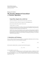
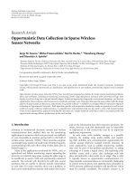
ThecooperationframefortheN relays is shown in Figure 1
andiscomposedofN subframes. Each one is divided into
two slots. In the sequel h, f
i
,andg
i
denote respectively the
instantaneous channel gains between source and destination,
source and node i, and node i and destination. w
i
and n
ik
de-
note, respectively, the additive noises at the ith relay node and
at the destination during the ith cooperation subframe and
the kth time slot. The channel gains are assumed to be in-
dependent, zero-mean complex gaussian distributed random
variables with variances σ
h
, σ
f
i
,andσ
g
i
. The additive noises
at the relay nodes and at the destination are assumed to be
independent, zero-mean gaussian distributed random vari-
ables with variance N
0
. We consider the NAF protocol pro-
posedin[4] which is a general cooperative protocol repre-
sentation since the OAF one and the direct transmission cor-
respond to particular power allocations per slot. The source
(s) transmits during the ith cooperation subframe duration
to the destination (d), the relay (r
i
) retransmits to the desti-
nation (d) by amplifying what it has received from the source
(s) during the first time slot. The system can be characterized
as follows:
y
d
i1
= h
P
1
x
i1
+ n
i1
,
y
d
i2
= h
P
2
x
i2
+ g
i
β
i
y
r
i
+ n
i2
,
y
r
i
= f
i
P
1
x
i1
+ w
i
,
(1)
where x
i1
and x
i2
are, respectively, the first and the second
symbols transmitted by the source during the ith cooperation
subframe. y
d
i1
and y
d
i2
are the first and the second symbols
received at the destination during the ith cooperation sub-
α
1
1
s
α
N
1
1
− α
1
r
1
1 − α
N
r
N
d
Tr an sm it
Receive
Figure 1: General cooperative frame for N relays.
frame. y
r
i
is the symbol received by the ith relay node from
the source, and β
i
is the scale factor of the ith relay node with
β
i
≤
P
r
i
P
1
| f
i
|
2
+ N
0
,(2)
where P
r
i
is the relay i transmitting power that should satisfy
the constrain
P
r
i
≤ P
max
r
i
(3)
and P
1
and P
2
are, respectively, the transmitting power of the
source at the first and the second slots. After vectorization,
the received frame can be written as
y
d
=
⎛
⎜
⎜
⎜
⎜
⎜
⎝
H
1
0 0
0H
2
0
.
.
.
.
.
. 0
.
.
.
0
0 0H
N
⎞
⎟
⎟
⎟
⎟
⎟
⎠
x + w,(4)
where y
d
= [y
d
1
, , y
d
N
]
t
with y
d
i
= [y
d
i1
, y
d
i2
], x = [x
1
, ,
x
N
]
t
with x
i
= [x
i1
, x
i2
],
H
i
=
⎛
⎜
⎜
⎜
⎜
⎜
⎜
⎝
h
P
1
N
0
0
f
i
g
i
P
1
β
i
N
0
1+β
2
i
g
i
2
h
P
2
N
0
1+β
2
i
g
i
2
⎞
⎟
⎟
⎟
⎟
⎟
⎟
⎠
(5)
is the normalized channel matrix and w is the noise vector
with w
∼N (0, I).
3. PROBLEM FORMULATION
We propose to determine the best protocol to use for a given
channel realization h, g
i
, f
i
, a fixed sum over all transmit-
ters power budget P
1
per slot and relays power constraints
P
max
r
i
. For this purpose, we consider the NAF protocol with
the general power allocation presented in Figure 1.Ateach
second slot per subframe i, the power P
1
is divided into a
part P
2
= α
i
P
1
allocated to the source and P
r
i
= (1 − α
i
)P
1
to the relay with 0 ≤ α
i
≤ 1. The power allocation is chosen
to maximize the mutual information between the source and
the destination
{α
1
, , α
N
}=arg max I
x, y
d
with
1 − α
i
P
1
≤ P
max
r
i
.
(6)
A. Saadani and O. Traor
´
e 3
Using (4) the mutual information is
I
x, y
d
=
log
2
det
I
2N
+ HH
H
=
N
i=1
I
x
i
, y
d
i
≤ N max
i
I
x
i
, y
d
i
,
(7)
where
I
x
i
, y
d
i
=
log
2
1+
|h|
2
P
1
N
0
+
|β
i
|
2
| f
i
|
2
|g
i
|
2
P
1
+ |h|
2
P
2
N
0
1+|β
i
|
2
|g
i
|
2
+
|h|
4
P
1
P
2
N
2
0
1+|β
i
|
2
g
i
2
.
(8)
Replacing β
i
by its maximum value (2), we obtain
I
x
i
, y
d
i
=
log
2
1+
|h|
2
P
1
N
0
+
| f
i
|
2
P
1
|g
i
|
2
P
r
i
+ |h|
2
P
2
N
0
+ | f
i
|
2
P
1
N
0
N
0
+ | f
i
|
2
P
1
+ |g
i
|
2
P
r
i
+
|h|
4
P
1
P
2
N
0
+ | f
i
|
2
P
1
N
2
0
N
0
+ | f
i
|
2
P
1
+ |g
i
|
2
P
r
i
.
(9)
Now, let a
0
=|h|
2
P
1
/N
0
, a
i
=|f
i
|
2
P
1
/N
0
and b
i
=|g
i
|
2
P
1
/N
0
.
By replacing P
2
and P
r
i
by their values it is easy to obtain that
I
x
i
, y
d
i
= log
2
1+a
0
+
a
i
b
i
1 − α
i
+ a
0
α
i
1+a
i
1+a
i
+ b
i
1 − α
i
+
a
2
0
α
i
1+a
i
1+a
i
+ b
i
1 − α
i
.
(10)
Hence, resolving problem (6)isequivalenttofindforevery
i the α
i
that maximizes (10) under the constraint that (1 −
α
i
)P
1
≤ P
max
r
i
. Once the optimal values α
opt
i
are obtained, the
upper bound (7) is achieved by communicating with only
one relay i
0
that satisfies I(x
i
0
, y
d
i
0
) = max
i
{I(x
i
, y
d
i
)}. This
selection leads to a short-term cooperation protocol choice
which could be NAF, OAF, or direct transmission.
4. PROTOCOL SELECTION
Resolving the formulated problem allows to find a method
that selects the best protocol based on the power available at
the relay nodes and the channel realizations.
Let A
i
= a
0
(1 + a
0
)(1 + a
i
) − b
i
(1 + a
0
+ a
i
), and B
i
=
a
i
b
i
+(1+a
0
)(1 + a
i
+ b
i
)andC
i
=−b
i
and D
i
= 1+a
i
+ b
i
.
Equation (10)isequivalentto
I
x
i
, y
d
i
=
log
2
A
i
α
i
+ B
i
C
i
α
i
+ D
i
. (11)
The behavior of (11) is reflected by its first derivative sign.
We show in the Appendix that for a fixed channels realization
h, f
i
,andg
i
the ∂I(x
i
, y
d
i
)/∂α
i
has a constant sign and hence
I(x
i
, y
d
i
) is a monotonous function of α
i
∈ [0, 1]. This is an
important result, indeed
(i)whenfunction(11) is increasing, we have α
opt
i
= 1
which means that the relay i should not cooperate;
(ii) when function (11) is decreasing, we have α
opt
i
=
max (1 − P
max
r
i
/P
1
, 0). Hence, the relay i can cooperate,
(iii) for each subframe, we should allocated all power to
the relay (i.e., α
opt
i
= 0) leading to an OAF protocol
choice. However, when this power exceeds the individ-
ual power constrain, it is reallocated to the source (i.e.,
α
i
= 1 − P
max
r
i
/P
1
) which means that the NAF protocol
is selected;
(iv) the optimal α
opt
i
is expected to have infinite possibil-
ities depending on h, f
i
,andg
i
, however there is only
two possible values which make the feedback very sim-
ple (only one bit per relay is needed).
In the sequel, the optimal power allocation per subframe i
respecting the power constraints on the relay i is detailed.
Without loss of generality, we distinguish two cases depend-
ing on the available power for all relays: if it is higher than the
source one or not.
4.1. Case P
max
r
i
≥ P
1
In this case, the constraint (1 − α
i
)P
1
≤ P
max
r
i
is always met
meaning that the relay i could transmit with power P
1
.The
power allocation scheme used to maximize the system capac-
ity is given by
α
opt
i
=
1ifA
i
D
i
− B
i
C
i
≥ 0,
0ifA
i
D
i
− B
i
C
i
< 0,
(12)
where A
i
D
i
−B
i
C
i
is the term determining the derivation sign
of (11) (see the Appendix). We recommend hence either the
OAF protocol (i.e., α
opt
i
= 1) presented in [2]ornottocoop-
erate with the relay i (i.e., α
opt
i
= 0). A relay station i will serve
during the subframe i if the global channel capacity when re-
laying the source’s signal to the destination is enhanced.
If there are more than one relay station and all of them
have the same power constraint, one can select for the global
cooperative frame the one that maximizes the following ex-
pression:
γ
i
=
a
i
b
i
1+a
i
+ b
i
. (13)
In fact, since α
opt
i
= 0, it is easy to show that (13) maximizes
(7) and the upper bound is achieved. The cooperative frame
will be reduced to only one subframe.
Our best relay selection leads to a selective OAF proto-
col that we call OAFPA (OAF with power allocation) pro-
tocol. We remind that selective OAF (S-OAF) protocol was
addressed in [2] where the selection is based on the outage
probability: The cooperation is used only when the direct
link is in outage. However in our protocol, the cooperation
can be used even if the direct link is not in outage since we
select the transmission method that maximizes the instan-
taneous capacity. Performance comparison between the two
protocols is done and discussed in Section 5.
4.2. Case P
max
r
i
≤ P
1
Here, the NAF protocol should be used, since the constraint
(1
− α
i
)P
1
≤ P
max
r
i
is met if and only if α
i
≥ (1 − P
max
r
i
/P
1
).
4 EURASIP Journal on Advances in Signal Processing
The power allocation scheme used to maximize the system’s
capacity is given by
α
opt
i
=
⎧
⎪
⎨
⎪
⎩
1ifA
i
D
i
− B
i
C
i
≥ 0,
1
−
P
max
r
i
P
1
if A
i
D
i
− B
i
C
i
< 0.
(14)
As previously stated, a relay station will only serve if it per-
forms better than the direct transmission. Unlike [4], there is
a relay selection depending on the channel realizations.
If there are more than one relay and all of them have
the same power constraint, using (7)and(11) one can easily
show that to achieve the upper bound of (α
i
/= 0), it suffices
to select only the relay that maximizes
γ
i
=
A
i
α
opt
i
+ B
i
C
i
α
opt
i
+ D
i
, (15)
since α
opt
i
/= 0.
5. SIMULATION RESULTS
We consider a symmetric network with equal channel vari-
ances σ
h
= σ
f
i
= σ
g
i
= 1. The relay number N is fixed to one
or three. The analyzed performance is the outage probability
and the capacity. The proposed protocols based on the opti-
mal power allocation with relay selection are compared with
the following.
(i) The S-OAF protocol proposed in [2] and reminded in
Section 4.1. Our proposed protocol is OAFPA (OAF
with power allocation).
(ii) The NAF protocol proposed in [4] since there is any
selective NAF yet known. We remind that the power
is equally divided between the source and the relay at
the second slot for every subframe [4]. Our proposed
protocol is called NAFPA.
For simplicity, we assume that all the relays have the same
maximum power P
max
r
i
. As previously, we distinguish hence
the following two cases.
5.1. Case P
max
r
i
≥ P
1
In order to satisfy the power constraint at the relay, the P
max
r
i
is fixed to P
1
.
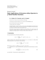
(1) Outage probability
Figure 2 compares the outage probability for N
= 1 and dif-
ferent transmitting rates R (bitsperchanneluse).Thepro-
posed solution and the S-OAF protocol have the same per-
formance because they have the same outage criterion. How-
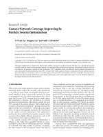
ever, for N
= 3 the OAFPA protocol gives the best per-
formance as shown in Figure 3. Indeed, it selects from the
three relays the one that maximizes the system capacity cor-
responding to the upper bound of (7) when it is higher than
the noncooperation ones. On the other hand, S-OAF tests
first if the direct link is in outage. If it is the case, it uses the
three relays to evaluate the capacity which is in general lower
than the upper bound of (7).
0102030405060
SNR (dB)
10
−3
10
−2
10
−1
10
0
Outage probability
Outage probability vs SNR in a symmetric one relay network
No cooperation
S-OAF
OAFPA
R
= 4
R
= 2
R
= 10
R
= 6
Figure 2: Outage probability comparison for orthogonal protocols,
N
= 1.
010203040506070
SNR (dB)
10
−4
10
−3
10
−2
10
−1
10
0
Outage probability
Outage probability vs SNR in a symmetric three relays network
No cooperation
S-OAF
OAFPA
R
= 4
R
= 2
R
= 10
R
= 6
Figure 3: Outage probability comparison for orthogonal protocols,
N
= 3.
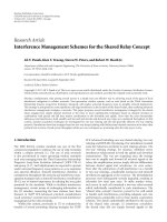
(2) Ergodic capacity
Unlike the outage probability, Figure 4 shows that even with
onerelaytheOAFPAprotocolcapacityoutperformstheS-
OAF ones. The ergodic capacity depends on R because this
parameter is used for the relay selection criterion in the S-
OAF protocol. The fact that it decides not to cooperate when
the direct link is not in outage, without considering if the
capacity when relaying is better, degrades the performance.
This is amplified for high spectral efficiencies R. The OAFPA
A. Saadani and O. Traor
´
e 5
10 20 30 40 50 60
SNR (dB)
10
0
10
1
Capacity (bit/s/Hz)
Capacity vs SNR in a symmetric one relay network
No cooperation
S-OAF
OAFPA
R
= 2
R
= 4
R
= 10
R
= 6
Figure 4: Ergodic capacity comparison for orthogonal protocols,
N
= 1 and minimum transmitting rate R.
protocol capacity is very close to the noncooperation ones
since the cooperation is not frequently decided for a sym-
metric network. Finally at very high SNR, the three protocols
have the same capacity since the direct transmission is always
selected.
5.2. Case P
max
r
i
<P
1
We assume that P
max
r
i
= 3P
1
/4 and hence P
1
/4 is used by the
source in the second slot.
(1) Outage probability
The outage probabilities with different spectral efficiencies R
are presented for N
= 1andN = 3, respectively in Figures 5
and 6. The NAFPA protocol outperforms the NAF protocol
for all cases thanks to the power allocation and the optimal
relay selection. The NAF protocol performance suffers from
the selection absence at low SNR.
(2) Ergodic capacity
In Figure 7, the NAFPA protocol capacity outperforms the
NAF one for all SNR for N
= 1. Indeed, this is due to the
selection of the best way to communicate that maximizes the
capacity. Both protocols have the same instantaneous capac-
ity only when the cooperation is decided.
6. CONCLUSION
In this work, we have proposed to find the best way to com-
municate under power constraints per slot at the relays. The
NAF, OAF, or noncooperation protocols choice is equivalent
010203040506070
SNR (dB)
10
−4
10
−3
10
−2
10
−1
10
0
Outage probability
Outage probability vs SNR in a symmetric one relay network
No cooperation
NAF
NAFPA
R
= 4
R
= 2
R
= 10
R
= 6
Figure 5: Outage probability comparison for nonorthogonal pro-
tocols, N
= 1.
010203040506070
SNR (dB)
10
−4
10
−3
10
−2
10
−1
10
0
Outage probability
Outage probability vs SNR in a symmetric three relays network
No cooperation
NAF
NAFPA
R
= 4
R
= 2
R
= 10
R
= 6
Figure 6: Outage probability comparison for nonorthogonal pro-
tocols, N
= 3.
to a power allocation problem to maximize the system capac-
ity. The solution showed that the cooperation mode per sub-
frame (OAF or NAF) depends only on the power constraints
at the relays. We gave simple conditions needed to decide to
cooperate or not. The obtained optimization leads to new
proposed cooperation protocols that combines power allo-
cation with relay selection (OAFPA and NAFPA protocols)
respecting the per slot constraints.
6 EURASIP Journal on Advances in Signal Processing
0 102030405060
SNR (dB)
10
0
10
1
Capacity (bit/s/Hz)
Capacity vs SNR in a symmetric one relay network
No cooperation
NAF
NAFPA
Figure 7: Ergodic capacity comparison for one relay and P
max
r
i
=
3P
1
/4.
APPENDIX
The first derivative of I(x
i
, y
d
i
)is
∂I
x
i
, y
d
i
∂α
i
=
1
ln2
A
i
D
i
− B
i
C
i
A
i
α
i
+ B
i
C
i
α
i
+ D
i
. (A.1)
From the expressions of A
i
, B
i
, C
i
,andD
i
given previously,
the following signs determination is obvious
B
i
> 0
D
i
> 0
C
i
< 0
−D
i
C
i
=
1+a
i
+ b
i
b
i
> 1
(A.2)
and hence
C
i
α
i
+ D
i
≥ 0, ∀α
i
∈ [0, 1]. (A.3)
The derivative sign analysis lies on the sign of A
i
. For this
purpose, two cases are distinguished.
Case A (A
i
≥ 0)
The numerator of (A.1) is hence positive and the sign de-
pends only on the denominator one. This latter is the prod-
uct of two linear functions of α
i
with α
i
∈ [0, 1]. The sign of
each one has to be determined and to make a product after-
wards.
Since A
i
≥ 0, the ratio −B
i
/A
i
≤ 0 and the function
(A
i
α
i
+ B
i
)arepositiveforallα
i
∈ [0, 1]. The positiveness of
the denominator lies on the function (C
i
α
i
+ D
i
) one which
is the case as shown in (A.3). We then deduce that
∂I
x
i
, y
d
i
∂α
i
≥ 0(A.4)
for α
i
∈ [0, 1] and the optimal choice is α
opt
i
= 1.
Case B (A
i
< 0)
Now, to obtain the sign of (A.1) two subcases need to be con-
sidered: A
i
D
i
− B
i
C
i
≥ 0andA
i
D
i
− B
i
C
i
< 0.
(1) Case A
i
D
i
− B
i
C
i
≥ 0
The mutual information derivative’s numerator is assumed
to be positive. First, we rewrite this numerator as
A
i
D
i
− B
i
C
i
= A
i
C
i
D
i
C
i
−
B
i
A
i
. (A.5)
Since A
i
< 0 and knowing that C
i
is always negative, (A.5)is
positive if and only if (D
i
/C
i
− B
i
/A
i
) > 0. That means that
−D
i
C
i
<
−B
i
A
i
. (A.6)
The derivative sign depends only on the denominator
(A
i
α
i
+ B
i
)(C
i
α
i
+ D
i
) ones. But using (A.3), it only depends
on the function A
i
α
i
+B
i
sign. It is easy to see that this latter is
always positive for all α
i
≤−B
i
/A
i
. On the other hand, from
(A.2)and(A.6)wehave
−B
i
/A
i
> 1 and consequently,
∂I
x
i
, y
d
i
∂α
i
≥ 0(A.7)
for α
i
∈ [0,1] and as previously the optimal choice is α
opt
i
=
1.
(2) Case A
i
D
i
− B
i
C
i
< 0
Similarly to the previous subcase, since A
i
< 0 and knowing
that C
i
≤ 0, the expression (A.5)isnegativeifandonlyif
(D
i
/C
i
− B
i
/A
i
) < 0. That means that
−D
i
C
i
>
−B
i
A
i
. (A.8)
Unlike the previous subcase, (A.8) does not show if the de-
nominator zero is greater than 1.
Anyway, it is easy to see that the denominator is positive
for all α
i
≤−B
i
/A
i
. Knowing that the numerator is negative,
the derivative is negative for all α
i
≤−B
i
/A
i
.Moreover,be-
fore saying that the derivative is negative for α
i
∈ [0, 1], we
ensure that
−B
i
/A
i
≥ 1 which is equivalent to A
i
+ B
i
≥ 0. By
using
A
i
+ B
i
= 1+a
0
+ a
i
+ a
0
a
i
+ a
0
1+a
0
1+a
i
,(A.9)
we have that A
i
+ B
i
is a sum of positive quantities and the
sum is always positive. We can now write
∂I
x
i
, y
d
i
∂α
i
≤ 0 (A.10)
for α
i
∈ [0, 1], however the power constraints at the relay
impose that the optimal choice is α
opt
i
= max (0, 1−P
max
r
i
/P
1
).
Using (A.4), (A.7), and (A.10) it is shown that (11)isa
monotonous function.
A. Saadani and O. Traor
´
e 7
ACKNOWLEDGMENT
The authors thank Mrs Ghaya Rekaya from Ecole Nationale
des Telecommunications de Paris for her precious arguments
andhelpinthiswork.
REFERENCES
[1] A. Sendonaris, E. Erkip, and B. Aashang, “User coorperation
diveristy—part1:systemdescription,”IEEE Transactions on
Communications, vol. 51, no. 11, 2003.
[2]J.Laneman,D.N.C.Tse,andG.W.Wornell,“Cooperative
diversity in wireless networks: efficient protocols and outage
behaviour,” IEEE Transactions on Information Theory, vol. 50,
no. 12, pp. 3062–3080, 2004.
[3] L. Zheng and D. N. C. Tse, “Diversity and multiplexing: a fun-
damental tradeoff in multiple-antenna channels,” IEEE Trans-
actions on Information Theory, vol. 49, no. 5, pp. 1073–1096,
2003.
[4] K. Azarian, H. El Gamal, and P. Schniter, “On the achiev-
able diversity-multiplexing tradeoff in half-duplex cooperative
channels,” IEEE Transactions on Information Theory, vol. 51,
no. 12, pp. 4152–4172, 2005.
[5] Y. Li, B. Vucetic, Z. Zhou, and M. Dohler, “Ditributed adapa-
tive power allocation for wireless relay networks,” IEEE Trans-
actions on Wireless Communications, vol. 6, no. 3, pp. 948–958,
2007.
[6] A. H. Madsen and J. Zhang, “Capacity bounds and power al-
location for wireless relay channels,” IEEE Transactions on In-
formation Theory, vol. 51, no. 6, pp. 2020–2040, 2005.
[7] J. Luo, R. S. Blum, L. Cimini, L. Greenstein, and A. Haimovich,
“Power allocation in a transmit diversity system with mean
channel gain information,” IEEE Communications Letters,
vol. 9, no. 7, pp. 616–618, 2005.
[8] D. G
¨
und
¨
uz and E. Erkip, “Opportunistic cooperation by
dynamic resource allocation,” IEEE Transactions on Wireless
Communications, vol. 6, no. 4, pp. 1446–1454, 2007.
[9] E. Beres and R. S. Adve, “On selection cooperation in dis-
tributed networks,” in Conference on Information Sciences and
Systems (CISS 2006), pp. 1056–1061, Princeton, NJ, March
2006.
[10] X. Deng and A. M. Haimovich, “Power allocation for coop-
erative relaying in wireless networks,” IEEE Communications
Letters, vol. 9, no. 11, pp. 994–996, 2005.
[11] M. O. Hasna and M S. Alouini, “Optimal power allocation
for relayed transmissions over rayleigh-fading channels,” IEEE
Transactions on Wireless Communications,vol.3,no.6,pp.
1999–2004, 2004.
[12] Y. Zhao, R. Adve, and T. J. Lim, “Improving amplify-and-
forward relay networks: optimal power allocation versus se-
lection,” in Wireless Communications, IEEE Transactions on
Wireless Communications, vol. 6, no. 8, pp. 3114–3123, August
2007.
[13] M. Pischella and J C. Belfiore, “Optimal power allocation for
downlink cooperative cellular networks,” in Proceeding of the
IEEE Vehicular Technology Conference (VTC ’07), pp. 2864–
2868, 2007.