Báo cáo hóa học: "Research Article Efficient Feedback via Subspace-Based Channel Quantization for Distributed Cooperative " ppt
Bạn đang xem bản rút gọn của tài liệu. Xem và tải ngay bản đầy đủ của tài liệu tại đây (1.04 MB, 13 trang )
Hindawi Publishing Corporation
EURASIP Journal on Advances in Signal Processing
Volume 2008, Article ID 847296, 13 pages
doi:10.1155/2008/847296
Research Article
Efficient Feedback via Subspace-Based Channel
Quantization for Distributed Cooperative Antenna Systems
with Temporally Correlated Channels
Jee Hyun Kim,
1
Wolfgang Zirwas,
1
and Martin Haardt
2
1
Nokia Siemens Networks GmbH & Co. KG, St Martin-Strasse 76, 81541 Munich, Germany
2
Communications Research Laboratory, Ilmenau University of Technology, P.O. Box 100565, 98684 Ilmenau, Germany
Correspondence should be addressed to Jee Hyun Kim,
Received 15 June 2007; Revised 28 September 2007; Accepted 23 November 2007
Recommended by Ana P
´
erez-Neira
It is one of the biggest challenges of distributed cooperative antenna (COOPA) systems to provide base stations (BSs) with down-
link channel information for transmit filtering (precoding). In this paper, we propose a novel feedback scheme via a subspace-based
channel quantization method. The proposed scheme adopts the chordal distance as a channel quantizer criterion so as to capture
channel characteristics represented by subspaces spanned by the channel matrix. We also propose a combined feedback scheme
which is based on the hierarchical codebook construction method in an effort to reduce the feedback overhead by exploiting the
temporal correlation of the channel. The proposed methods are tested for distributed COOPA systems in terms of simulations.
Simulation results show that the proposed subspace-based channel quantization method outperforms the analog pilot retransmis-
sion method, and the combined feedback scheme performs as well as the permanent full-feedback scheme with a much smaller
amount of uplink resources.
Copyright © 2008 Jee Hyun Kim et al. This is an open access article distributed under the Creative Commons Attribution License,
which permits unrestricted use, distribution, and reproduction in any medium, provided the original work is properly cited.
1. INTRODUCTION
Cooperative antenna (COOPA) systems have recently be-
come a hot research topic, as they promise significantly
higher spectral efficiency than conventional cellular systems
[1]. COOPA systems are also termed coordinated network
systems in some references [2–5]. The gain is acquired by
adopting intercell interference (ICI) cancelation schemes,
for example, joint transmission/joint detection (JT/JD) algo-
rithms. An improvement factor of more than 5 in spectral
efficiency is observed for COOPAsystems with an antenna
arrangement of 4 transmit antennas per base station and 4
receive antennas per user, compared with uncoordinated cel-
lular systems [2]. In COOPA systems, several adjacent base
stations (BSs) are cooperating so as to support multiple mo-
bile stations (MSs) which are located in the correspond-
ing cooperative area (CA). Therefore, COOPA systems can
be regarded as a multiuser multiple-input multiple-output
(MU-MIMO) system, in which multiple transmit antennas
at the BS, which are conventionally considered to be located
in one BS, are spread over several BSs. This distributed na-
ture, which is attributed to the fact that several geographi-
cally distributed BSs are used as transmit antennas, leads to
full macro-diversity gains. Moreover, COOPA systems have
advantageous features compared with conventional cellular
systems, for example, increased degrees of freedom, better
ICI cancelation performance, the rank enhancement effect of
the channel matrix, and so forth, [1]. In addition, JT/JD al-
gorithms of COOPA systems calculate a common weighting
matrix for all BSs, cancel ICI, and allow the system to serve
multiple MSs at the same time and frequency resource. This
leads to a real-frequency reuse equal or close to 1.
COOPA systems are based on the cooperation between
multiple distributed BSs. This means that COOPA systems
need a fast and efficient backbone network as well as the cen-
tral unit (CU) which manages the cooperation amongst as-
sociated BSs. The CU renders the overall network structure
more complex by adding one more layer in the hierarchy, and
eventually increases the costs. In [6], distributed organiza-
tion methods have been suggested to address this problem.
One of the main challenges of the distributed COOPA
system is channel estimation for the downlink channel. All
2 EURASIP Journal on Advances in Signal Processing
of the associated BSs in the CA need to know the full channel
state information to calculate the corresponding precoding
weight matrix. This information is needed to be transferred
from MSs to BSs by using uplink resources. As several BSs
and several MSs are involved in COOPA systems and each BS
and MS may be equipped with multiple antennas, the num-
ber of channel state parameters to be fed back is expected to
be big. In an effort to reduce the amount of feedback, the
analog pilot retransmission method has been suggested and
tested in [6], but the throughput of this method reaches only
40% of that of the ideal case, which requires supplementary
feedback schemes [1].
On the other hand, finite rate feedback strategies in
MIMO systems have been extensively investigated recently.
Beamforming codebook design methods are suggested based
on Grassmannian packing [7] and systematic unitary design
[8], which guarantee substantial gains with just a small num-
ber of feedback bits. A precoding matrix codebook construc-
tion method, which is designed to maximize the mutual in-
formation, has been developed based on vector quantization
(VQ) techniques [9, 10]. These methods are designed to se-
lect a beamforming vector for the MISO case or a precod-
ing matrix for the MIMO case from a set of codes. They are
developed for point-to-point MIMO channels, in which the
transmitter serves one receiver at a time. In the single-user
MIMO (SU-MIMO) case, it is known that even a small num-
ber of bits per antenna can be quite beneficial [11]. In the
multiuser MIMO (MU-MIMO) case, feedback rate scaling is
required to achieve a throughput close to that with perfect
feedback information in order to compensate for the inter-
ference between users [12]. The analysis in [12]isbasedon
the case when a user selects the precoding matrix by solely
looking at its own channel without considering the interfer-
ence to other users which is caused by adopting that precod-
ing matrix. Hence, a better way to handle interuser interfer-
ence needs to be addressed.
In this paper, we propose a subspace-based channel
quantization method which guarantees a much higher per-
formance than the analog pilot retransmission method. We
also propose an iterative codebook design algorithm which
converges to a locally optimum codebook. Furthermore, as a
feedback reduction scheme, we propose a hierarchical code-
book design method. The proposed schemes can be used for
cellular MU-MIMO systems as well, which involve one BS for
downlink data transmission.
Notation
Vectors and matrices are denoted by lower case bold and cap-
ital bold letters, respectively. (
·)
T
and (·)
H
denote transpose
and Hermitian transpose, respectively. The inner product be-
tween two vectors is defined as
u, v=u
H
v.tr (·)denotes
the trace of a matrix.
|·|, ·
2
,and·
F
denote the magni-
tude of a scalar, the two-norm of a vector or a matrix, and the
Frobenius norm of a matrix, respectively. The covariance ma-
trix of the vector process x is denoted by R
x
= E[xx
H
], where
E[·] is used for expectation. I
N
is the N × N identity matrix
and 0
M×N
stands for an all-zero matrix of size M×N. I
M×N
is
defined as I
M×N
:= [
I
N
0
(M−N )×N
]forM>N.[A]
i,j
stands for the
(i, j)th entry of a matrix A.
|S| is the cardinality of a set S.
2. SYSTEM MODEL AND MOTIVATION FOR
CHANNEL QUANTIZATION METHOD
We consider a precoded MU-MIMO system in which a group
of BSs transmits data to multiple MSs simultaneously. Each
of N
BS
BSs and each of N
MS
MSs have N
t
and N
r
antennas,
respectively. The data symbol block, s
= [s
1
, , s
N
tr
]
T
with
N
tr
= N
MS
N
r
,isprecodedbyanN
tt
× N
tr
matrix W with
N
tt
= N
BS
N
t
, in case that the number of data streams for each
user n
s
(n
s
≤ N
r
)isN
r
. Here, the first N
r
data symbols are
intended for the first user, the next N
r
symbols for the second
user, and so on. When denoting i
BS
/i
MS
as the BS/MS index
and i
t
/i
r
as the transmit/receive antenna index, respectively,
we can denote h
i,j
,wherei = N
r
(i
MS
−1)+i
r
, j = N
t
(i
BS
−1)+
i
t
as the channel coefficient between the i
r
th receive antenna
of the i
MS
th MS and the i
t
th transmit antenna of the i
BS
th BS.
The N
tr
N
tt
channel coefficients can be expressed as the N
tr
×
N
tt
channel matrix H with [H]
i,j
= h
i,j
. The received signals
on N
tr
receive antennas which are collected in the vector y
can be formulated as
y
= HWs + n,(1)
where n is additive white Gaussian noise (AWGN). The sig-
nal model appears to be very similar to that of the single-
user MIMO case at a first glance, but the difference lies in the
fact that the channel matrix in our case contains elements
belonging to multiple BSs and multiple MSs.
There are several available techniques developed for
downlink transmit filtering in MU-MIMO systems. Linear
precoding techniques (e.g., transmit matched filter (TxMF),
transmit zero-forcing filter (TxZF), and transmit Wiener fil-
ter (TxWF)) have an advantage in terms of computational
complexity [13]. Nonlinear techniques (e.g., Tomlinson-
Harashima precoding (THP)) have a higher-computational
complexity but can usually provide a better performance
than linear techniques [14, 15]. Some linear techniques (e.g.,
block diagonalization (BD) and successive minimum mean
squared error precoding (SMMSE)) are developed for the
case in which there are multiple antennas at each receiver.
The BD algorithm is designed to eliminate multiuser inter-
ference (MUI) [16]. BD outperforms the TxZF and asymp-
totically approaches the sum capacity of the channel at high
SNR. SMMSE performs better than some nonlinear tech-
niques (e.g., successive optimization (SO) THP and MMSE
THP) with a relatively low-computational complexity [17].
In our case, we adopt the TxZF which completely suppresses
the interference at the receiver [13] as follows:
{W, g}=arg min
{W,g}
|g|
2
tr
R
n
s.t.: gHW = I
N
tr
, tr
WR
s
W
H
= P
tx
(2)
where P
tx
, R
n
,andR
s
are the maximum transmit power, the
covariance matrix of the noise, and the covariance matrix of
the data symbol, respectively. The TxZF strategy, while gen-
erally suboptimal, is known to achieve the same asymptotic
Jee Hyun Kim et al. 3
sum capacity as that of dirty paper coding (DPC) which is the
optimal (channel capacity achieving) method, as the number
of users goes to infinity [18]. The transmit precoding matrix
W which satisfies the design criteria (2) takes the following
form:
W
= g
−1
H
H
HH
H
−1
,
where g
=
tr
HH
H
−1
R
s
P
tr
.
(3)
The challenge here is that BSs should know the downlink
channel matrix H so as to construct the precoding matrix W.
The analog pilot retransmission method has been proposed
as a way of transferring channel state information to the BS
[6]. As shown in [6], the analog pilot retransmission method
is vulnerable to noise enhancement effects and this weakness
of the analog method brings about a significant performance
degradation, even though it is efficient in terms of required
resources. As a way of combating noise, a digital method can
be used instead of the analog method. A digital method im-
plies that MSs measure the downlink channel and encode this
information into a digital code and send it back to the BSs af-
ter performing appropriate digital signal processing (modu-
lation, spreading, repetition, or channel coding, etc.) to guar-
antee robust data transmission.
As it is explained in the previous section, most of the fi-
nite rate feedback strategies in MIMO systems are designed
for the single user case, focusing on the selection and con-
struction of the precoding matrix codebook. If this strategy
is directly applied to the multiuser case, the performance will
be degraded since the user is supposed to select the precoding
matrix which is suitable in terms of its criterion (e.g., maxi-
mizing the mutual information or SNR), which may cause a
severe interference to other users. Here, we propose to quan-
tize the channel from the MS side instead of quantizing the
precoding matrix. Both methods are similar from the signal
processing perspective in the sense that both schemes com-
press the information in a matrix, while the channel quanti-
zation method is better positioned to cope with interuser in-
terferences. The BSs, after receiving feedback messages from
the MSs, can now build a precoding matrix with interuser
interferences taken into account, since the transmitters have
the whole channel state information, albeit it is not perfect
due to the limited feedback.
One way of quantizing the channel matrix is to view the
channel matrix as a set of complex matrices, and to quan-
tize every individual matrix by looking up a predefined code-
book. As explained above, the overall channel matrix is an
N
MS
N
r
×N
BS
N
t
matrix, and is composed of the channel ma-
trices for each user, which are of size N
r
× N
BS
N
t
.Equation
(4) depicts this relationship as follows:
H
=
H
1
, , H
j
, , H
N
MS
T
, j : user index. (4)
Here, H
j
is the transpose of the channel matrix for user j,
which is an N
BS
N
t
×N
r
matrix. If we allocate n
CB
bits for the
codebook, we need n
CB
N
MS
bits in total for every subcarrier.
This method is suitable for the limited feedback in terms of
required feedback bits, and the conventional vector quantiza-
tion (VQ) method can be applied with some modifications.
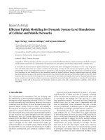
The system model is depicted in Figure 1.TheN
BS
BSs
need overall downlink channel state information H for the
calculation of the precoding matrix W so as to form multi-
ple spatial beams which enable independent and decoupled
data streams for N
MS
users. The individual user j estimates
its portion of the channel H
j
and quantizes it by finding the
best candidate from the predefined set of codes C
i
. The in-
dex of the chosen code i
j
is sent back to the BSs through the
limited feedback channel. The BSs reconstruct the channel
matrix
H by looking up the codebook, which is shared by
transmitters and receivers. This reconstructed channel ma-
trix is used for the calculation of the precoding matrix W.
We should note that in this case all of the N
BS
-associated BSs
have the same channel matrix, as long as the feedback mes-
sages are received without errors. In case of the analog pilot
retransmission method, the individual BS has its own version
of the channel matrix, which is in general different from each
other due to the nature of the analog transmission scheme,
and this entails a significant performance degradation [1, 6].
The principles of the analog pilot retransmission method can
be found in [1, Section 10.3.3.1].
3. SUBSPACE-BASED CHANNEL
QUANTIZATION METHOD
As proposed in the previous section, MS j is supposed to
quantize its channel matrix H
j
.WeviewH
j
not just as a
complex matrix but as a subspace which is spanned by its
columns. We perform a singular value decomposition (SVD)
to extract the unitary matrix U
j
which includes the basis vec-
tors U
(S)
j
spanning the column space of H
j
(H
j
: N
tt
×N
r
, U
j
:
N
tt
× N
tt
, U
(S)
j
: N
tt
× N
r
). Here, the superscripts (S) and (0)
are used to denote a basis for the signal subspace and the null
space, respectively,
H
j
= U
j
Σ
j
V
H
j
, U
j
=
U
(S)
j
U
(0)
j
. (5)
The channel quantizer uses the chordal distance as a distance
metric, since we should measure the distance between sub-
spaces. There are other subspace distance metrics [19], but
the chordal distance is the one which leads us to an analytic
solution when designing the codebook [20]. The chordal dis-
tance is defined as
d
c
T
i
, T
j
=
1
√
2
T
i
T
H
i
−T
j
T
H
j
F
(6)
for matrices T
i
, T
j
which have orthonormal columns.
The quantized version of the column space basis vectors
U
(S)
j
is chosen to be the code which has the minimum chordal
distance from it. Thus, the subspace quantization process can
be written as
U
(S)
j
= Q
U
(S)
j
=
arg min
C
i
∈C
d
c
U
(S)
j
, C
i
,(7)
where C is the codebook of size N (N
= 2
n
CB
) which has
the code C
i
∈ C
N
tt
×N
r
as its elements. Here, C
i
has unitary
4 EURASIP Journal on Advances in Signal Processing
H
BS1
W
BS N
BS
MS1
MS N
MS
Feedback
i
1
, , i
N
MS
C
i
1
= Q(H
1
)
C
i
N
MS
= Q(H
N
MS
)
H
=
C
i
1
··· C
i
N
MS
T
H =
⎡
⎢
⎢
⎢
⎣
H
1
··· H
N
MS
⎤
⎥
⎥
⎥
⎦
T
.
.
.
.
.
.
.
.
.
.
.
.
.
.
.
.
.
.
Figure 1: COOPA system downlink with N
BS
cooperating base stations and N
MS
mobile stations.
columns (C
H
i
C
i
= I
N
r
), hence the code represents only the
column space of H
j
. No channel magnitude information is
fed back to the transmitter, since extensive simulation results
show that extra magnitude information does not improve the
system performance, compared with the case in which only
the code index is provided to the transmitters when the link
strengths (large-scale fading due to path loss and shadowing)
are assumed to be provided at the BSs. In the case that chan-
nel magnitude information is to be fed back, the quantized
version of the channel at the transmitter which takes this into
account can be formulated as
H
j
=
U
(S)
j
Σ
(S)
j
,(8)
where Σ
(S)
j
∈ R
N
r
×N
r
+
is a diagonal matrix which is composed
of N
r
×N
r
elements in the upper left-hand corner of Σ
j
.The
diagonal elements of Σ
(S)
j
constitute the channel magnitude
information, which can be regarded as a refinement of the
link strengths which are already available at the BSs. This
channel quantization model (8)canprovideabetterviewof
the channel, as it considers not only the channel directional
information, but also the channel magnitude information
(link strength refinement information). However, the sim-
ulation results show that this extra information does not en-
hance the system performance in terms of SINR, compared
with the case in which only the channel directional informa-
tion is provided. Some of the simulation results can be found
in Section 6. It is known that the performance can be im-
proved by providing the transmitter with the channel quality
information (e.g., SINR) in addition to the directional in-
formation (the column space basis vectors), when a multi-
antenna downlink system carrying more users than transmit
antennasisconsidered[21]. In our case, the multiuser di-
versity gain is not considered at the moment, so we focus
on the directional information of the channel. The bottom
line is that the MS needs to quantize the column space of H
j
only. The channel magnitude information contained in Σ
j
is, therefore, not required. In this case, the MS is supposed
to send only n
CB
bits of feedback. The channel quantization
formula can be simplified as
H
d
j
=
U
(S)
j
= arg min
C
i
∈C
d
c
U
(S)
j
, C
i
. (9)
The superscript d implies that the channel is quantized in
terms of the direction, with its magnitude information ig-
nored.
The subspace-based channel quantization method works
as follows. MS j finds the code C
i
which provides the mini-
mum chordal distance with U
(S)
j
. Then, it sends back an n
CB
bit code index to all associated BSs. The reconstructed down-
link channel matrix at the BSs is as follows:
H =
H
d
1
, ,
H
d
j
, ,
H
d
N
MS
T
, j : user index. (10)
Finally, the BSs calculate the TxZF precoding matrix W by
using the reconstructed channel matrix
H as follows:
W
= g
−1
H
H
H
H
H
−1
, (11)
Jee Hyun Kim et al. 5
where g is the normalization factor imposed by the transmit
power constraint (3). (Actually, it is not a true zero-forcing
precoding matrix in the strict sense, since the channel mag-
nitude information is not considered. In this paper, we use
the term TxZF interchangeably for this particular case, as-
suming that readers are not to be confused.)
It is worth noticing that the channel quantization crite-
rion (9) can be expressed as
h
j
= arg max
c
i
∈C
v
j
, c
i
,wherev
j
=
h
j
h
j
2
, (12)
for the MISO case where the MS is equipped with one an-
tenna. In this case, the task of quantizing the channel boils
down to that of quantizing the channel vector, instead of the
channel matrix. It basically selects the code of which the di-
rection is closely aligned with the direction of the channel.
Here, the channel to be quantized, the directional informa-
tion of the channel, and the corresponding code are all vec-
tors of the same size (h
j
, v
j
, c
j
∈ C
N
tt
×1
). For the proof of this
formula, please refer to the appendix.
4. CODEBOOK CONSTRUCTION BASED ON
MODIFIED LBG VQ ALGORITHM
The Grassmannian subspace packing is optimal in terms of
quantization for the uncorrelated Rayleigh fading channel
[7]. The Grassmannian space G(m, n) is the set of all n-
dimensional subspaces of the space
C
m
, and the Grassman-
nian subspace packing problem is the problem of finding
the best packing of Nn-dimensional subspaces in
C
m
.The
best packing means that N points in G(m, n) are maximally
spaced such that the minimal distance between any two of
the subspaces is as large as possible.
In our case, the Linde, Buzo, and Gray (LBG) vector
quantization (VQ) algorithm [22] is used to construct the
codebook C. The LBG VQ algorithm is an iterative algorithm
based on the Lloyd’s algorithm which is known to provide an
alternative systematic approach for the Grassmannian sub-
space packing problem [20]. We in this paper acquire the
codebook through the iterative algorithm described in [20].
The main difference of the proposed method is attributed
to the fact that the codebooks in [20] are precoder code-
books, while the codebooks to be constructed here are chan-
nel quantizer codebooks. The proposed algorithm aims at
finding a tradeoff between good quantization properties and
the Grassmannian subspace packing requirements by adopt-
ing the minimum chordal distance of the codebook as a de-
cision criterion for iterations.
4.1. Design issue
The LBG-VQ-based codebook C design problem can be
stated as follows. For a given source vector, a given distortion
measure, a given codebook evaluation measure, and given
the size of the codebook, find a codebook and a partition
which result in maximizing the minimum chordal distance
of the codebook. (The partition of the space is defined as the
set of all encoding regions.) In other words, we want to find
maximally spaced N points in G(N
tt
, N
r
) with given channel
realization samples.
Suppose that we have a training sequence T to capture
the statistical properties of the column space basis vectors
U
(S)
j
of size N
tt
×N
r
:
T
=
X
1
, X
2
, , X
M
, (13)
where X
m
∈ C
N
tt
×N
r
is a sample of U
(S)
j
which can be obtained
by taking an SVD of the channel matrix H
j
.Thecodebook
can be represented as follows:
C
=
C
1
, C
2
, , C
N
. (14)
The individual code is of the same size as a training matrix
(C
n
∈ C
N
tt
×N
r
). Let R
n
be the encoding region associated
with the code C
n
and let
P
=
R
1
, R
2
, , R
N
(15)
denote the partition of the space. (The encoding region is
called a Vorono i cell in some publications.) If the source ma-
trix X
m
belongs to the encoding region R
n
, then it is quan-
tized to C
n
as follows:
Q
X
m
=
C
n
,ifX
m
∈ R
n
. (16)
Our aim is to find a codebook of which the minimum
chordal distance is maximized. There are several subspace
distance metrics, for example, the Fubini-Study distance, the
projection two-norm distance, and the chordal distance met-
rics. It has been shown that the chordal distance is the only
distance measure which makes the iterative algorithm feasi-
ble [20]. The minimum chordal distance of the codebook is
given by
d
c,min
(C):= min d
c
C
i
, C
j
,forC
i
, C
j
∈ C, ∀i
/
= j. (17)
The design problem can be stated as follows. Given T and N,
find C and P such that d
c,min
(C) is maximized:
C
opt
= arg max
C
d
c,min
(C). (18)
4.2. Optimality criteria
C and P must satisfy the following two criteria so as to be
a solution to the above-mentioned design problem [22]. We
should note that the chordal distance is used as a distance
metric.
(i) Nearest neighbor condition:
R
n
=
X : d
c
X, C
n
<d
c
X, C
n
, ∀n
/
=n
. (19)
This condition says that any channel sample X,whichis
closer to the code C
n
than any other codes in the chordal dis-
tance sense, should be assigned to the encoding region R
n
,
and be represented by C
n
.
(ii) Centroid condition:
C
n
= U
R
I
N
tt
×N
r
, (20)
6 EURASIP Journal on Advances in Signal Processing
Table 1: The minimum codebook distances d
c,min
(C).
(N
tt
, N
r
) n
CB
mLBG VQ Grassmann
(2, 1) 3 0.3895 0.3820
(3, 1)
3 0.5706 0.5429
4 0.4882 0.4167
where U
R
is an eigenvector matrix of the sample covariance
matrix R which is defined as
R :
=
1
N
R
n
X
m
∈R
n
X
m
X
H
m
,whereN
R
n
=
R
n
, (21)
provided that eigenvalues in the eigenvalue matrix Σ
R
of R =
U
R
Σ
R
U
H
R
are sorted in the descending order. This condition
means that the code C
n
of the encoding region R
n
should be
the principal eigenvectors of the sample covariance matrix R,
meaning the N
r
eigenvectors of R corresponding to N
r
largest
eigenvalues. The centroid condition is designed to minimize
the average distortion in the encoding region R
n
, when C
opt
n
represents R
n
[20].
4.3. Modified LBG VQ algorithm
The modified LBG VQ (mLBG VQ) design algorithm is an it-
erative algorithm which finds the solution satisfying the two
optimality criteria in Section 4.2. The algorithm requires an
initial codebook C
(0)
. C
(0)
is obtained by the splitting of an
initial code, which is the centroid of the entire training se-
quence, into two codes. The iterative algorithm runs with
these two codes as the initial codebook. The final two codes
are split into four and the same process is repeated until
the desired number of codes, which leads to the minimum
chordal distance, is obtained.
The minimum distances of the codebooks are collected
in Tab le 1 . A training sequence of the length 50,000 is used
for obtaining the codebook. It shows that the codebooks ac-
quired by the modified LBG VQ algorithm have better dis-
tance properties than the Grassmannian codebooks listed in
[23].
5. COMBINED CODEBOOK: HIERARCHICAL
CODEBOOK DESIGN METHOD
In this section, we propose a hierarchical codebook design
method, which exploits the temporal correlation of the chan-
nel, as a way of reducing the feedback overhead. It is known
that the wireless channel does not change radically within the
coherence time T
c
. Accordingly, the code index would not
change so often during this time period, since the code in-
dex can be considered as a channel state indicator. On the
other hand, we can easily draw the conclusion that the code-
book index transition rate over time is dependent on the size
of the codebook, which decides the resolution of the chan-
nel quantizer. It means that for a given channel, a bigger size
R
i
c
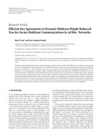
(a) Coarse encoding region
R
i
c
,i
f
(b) Fine encoding region
Coarse
codebook index
Fine code index
i
c
i
f
τ
c
τ
f
t
(c)
Figure 2: Coarse/fine encoding regions and feedback time frame.
codebook (fine codebook) has a higher capability of differen-
tiating encoding regions than a smaller size codebook (coarse
codebook). The period during which the coarse codebook
provides the same code index (let us call this a nontransi-
tion period) can be composed of several shorter nontransi-
tion periods when the fine codebook is used to quantize the
channel.
Thus, if we are able to design a codebook hierarchically
so that a codebook has several layers, say two layers, one of
which represents coarse encoding regions and another pro-
vides fine encoding regions, we can achieve the performance
of a fine channel quantizer by using much smaller feedback
resources. This can be achieved by organizing the coarse/fine
codebook feedback periods in a smart way to take advantage
of nontransition periods of the coarse/fine codebook.
The operation scenario of the combined codebook is as
follows. As a preparation, we need to design the combined
codebook which has a two-layer structure, namely, an n
c
bit
coarse codebook and an n
f
bit fine codebook. Correspond-
ing feedback periods should be decided, based on the statisti-
cal properties of the nontransition time. The n
t
= n
c
+ n
f
bit
combined codebook, as a whole, is designed to be composed
of 2
n
c
groups of the fine codes, and each fine codebook group
consists of 2
n
f
fine codes. The feedback operation works as
follows. For every coarse feedback period τ
c
of the n
c
bit
coarse codebook, the MS sends the coarse codebook index i
c
(n
c
bit) back to the BSs to indicate the fine codebook group
index to which the subsequent fine code indices belong. At
the same time, the MS sends the fine code index i
f
(n
f
bit)
to indicate the fine code index of the chosen fine codebook
group. This subsequent feedback is done for every fine feed-
back period τ
f
of the n
t
bit fine codebook. Since that, n
c
bit
feedback is sent back for every τ
c
and only n
f
bit extra feed-
back is needed for every τ
f
, we can save uplink resource when
compared to the case of sending back n
t
bit feedback for ev-
ery time. Interested readers can consult Figure 2 for better
understanding.
Jee Hyun Kim et al. 7
5.1. Hierarchical codebook construction
The main design problem of hierarchical codebook construc-
tion is to divide a coarse encoding region into equally proba-
ble fine encoding regions. Here, the term “equally probable”
means that the probability that a channel sample falling into
a certain encoding region is the same for all candidate en-
coding regions. Equally probable encoding regions allow us
to fix the feedback period for given channel-dependent con-
straints.
The modified LBG VQ (mLBG VQ) algorithm, which
is used for codebook construction, generates the codebook
which pertains this property. The resulting codes are maxi-
mally spaced codes of which an individual code is designed
to provide the minimum mean squared chordal distance
between the code and the channel samples in that encod-
ing region. This criterion places finer encoding regions in
densely populated areas, and the resulting encoding regions
are asymptotically equally probable. This is shown to be true
in [24] as well, for codes generated by the Lloyd’s algorithm-
based codebook construction method.
The design problem of hierarchical codebook construc-
tion with an n
c
bit coarse and an n
t
bit fine codebook is to
divide the given channel space which is a subspace of
C
N
tt
×N
r
into 2
n
c
equally probable coarse encoding regions and to di-
vide each coarse encoding region into 2
n
f
equally probable
fine encoding regions. In the end, we want to have 2
n
c
groups
of codebooks each of which is composed of 2
n
f
codes. This
canbesolvedasfollows.WefirstperformthemLBGVQalgo-
rithm to get N
c
= 2
n
c
coarse codes and corresponding coarse
encoding regions. These encoding regions are supposed to
be equally probable (P
n
= 1/N
c
, ∀n ∈{1, , N
c
}). Then,
we perform the mLBG VQ for channel samples which be-
long to each coarse encoding region, individually. As a result
of N
c
parallel codebook generation processes for each coarse
encoding region, we can acquire N
cb
= 2
n
t
= 2
n
c
+n
f
fine codes
with corresponding equally probable fine encoding regions
(P
n
= 1/N
f
, ∀n ∈{1, , N
f
}). Each coarse encoding region
consists of N
f
= 2
n
f
fine encoding regions.
The overall codebook C canberegardedasasetofcode-
books C
c
i
c
,wherei
c
is the codebook index. Here, we differ-
entiate between the terms code and codebook, in such a way
that a code indicates an individual code, whereas a codebook
indicates a set of codes. Thus i
c
indicates not an individual
code index, but a codebook index to which a fine code be-
longs. It means that the codebook C
c
i
c
is constructed based
on the i
c
th coarse encoding region R
i
c
. The elements of C
c
i
c
arefinecodes.TheoverallcodebookC and the i
c
th fine code-
book C
c
i
c
can be expressed as
C
=
C
c
1
, C
c
2
, , C
c
N
c
=
C
1
, C
2
, , C
N
cb
, (22)
C
c
i
c
=
C
i
c
1
, C
i
c
2
, , C
i
c
i
f
, , C
i
c
N
f
,fori
c
∈
1, 2, , N
c
,
(23)
where fine codes are arranged in such an order that the con-
dition C
i
c
i
f
= C
(i
c
−1)N
f
+i
f
∈ C
N
tt
×N
r
is satisfied and i
f
is the
fine code index within the coarse encoding region R
i
c
.Itbe-
comes clear at this point that the resulting codebook has a
hierarchical structure. This is the reason why it is termed a
hierarchical codebook.
For example, Figure 2 shows the case with n
c
= 3and
n
f
= 2. The partition of the channel sample space consists of
N
c
= 8 coarse encoding regions, the i
c
th of which is denoted
as R
i
c
, as a result of the mLBG VQ procedure. Each individ-
ual coarse encoding region is again decomposed into N
f
= 4
fine encoding regions, the i
f
th of which is R
i
c
,i
f
in case that
it is based on R
i
c
. In the end, we get N
cb
= 32 fine codes
associated with the corresponding fine encoding regions.
5.2. Operation scenario
The operation scenario of the hierarchical codebook deploy-
ment, which is also termed a combined codebook in this arti-
cle, is as follows.
(i) Coarse feedback: feedback of the codebook index i
c
.
For every coarse feedback period τ
c
, the MS sends the
n
c
bit codebook index i
c
back to the associated BSs
so as to indicate the chosen codebook. Based on the
channel information observed for the time period τ
c
,
the MS quantizes the channel matrix and finds the best
code in terms of the chordal distance. The index of the
chosen code C
(i
c
−1)N
f
+i
f
∈ C
N
tt
×N
r
can be decomposed
into two parts, for example, the codebook index part
i
c
and the code index part i
f
. The coarse feedback in-
volves sending back i
c
.
(ii) Fine feedback: feedback of the code index i
f
.
For every fine feedback period τ
f
within τ
c
, the MS
sends the n
f
bit code index i
f
back to the associated
BSs so as to indicate the chosen code. It means that
the MS performs the channel quantization for every
τ
f
, but the scope of candidate codes is restricted within
the codebook C
c
i
c
. This can save a lot of computational
burden for the MS, since the number of candidate
codes is N
f
instead of N
c
N
f
. The fine feedback involves
sending back i
f
.
The BSs collect the coarse and fine feedback messages,
and combine this information to find the chosen code, which
is one of N
cb
= 2
n
c
+n
f
fine codes which are predefined and
sharedbybothBSsandMSs.
There are several points to be worth our attention.
(1) The feedback periods τ
c
and τ
f
have a significant ef-
fect on the system performance. It is a challenging task
to find an analytical solution for calculating an opti-
mum feedback period. The optimization problem is
supposed to maximize the performance or to mini-
mize the performance degradation compared with the
ideal case (τ
c
, τ
f
are equal to the shortest possible feed-
back period), and it is a function not only of the di-
mension of the channel matrix to quantize, the speed
of the MS, and the carrier frequency, but also of the
number of feedback bits n
c
, n
f
which decide the reso-
lution of the channel quantizer.
(2) Once found, τ
c
and τ
f
can have fixed values for
given channel-related parameters (the channel matrix
dimension, the carrier frequency, and the speed of
8 EURASIP Journal on Advances in Signal Processing
BS
1
MS
1
Sector
BS
3
BS
2
MS
2
Cell
Cooperative area
BS
1
h
11
h
21
MS
1
h
12
h
13
BS
3
h
23
MS
2
BS
2
h
22
Figure 3: CA topology based on 3-sector-cell system.
the MS) and the number of feedback bits, and are still
able to guarantee the target performance. Therefore,
we do not need a feedback period of variable length
for given circumstances, which makes the system de-
sign problem easy. If parameters other than the mobile
speed remain same, we only need to scale the feedback
period with respect to the mobile speed.
(3) Within the coarse feedback period τ
c
, the resulting
codebook has a limited scope, since it selects the best
code from the chosen codebook only. If the actual
channel realization falls into a different coarse encod-
ing region, the quantization error would be significant.
The BS may benefit from saving the coarse codebook
C
c
={C
c
1
, C
c
2
, , C
c
N
c
} into memory, just in case that MSs
are temporarily disabled to send fine feedback messages to
BSs. In this case, the BSs are accessible to coarse feedback in-
dices only. However, the BSs can still reconstruct the chan-
nel if the coarse codebook is available at the BSs. The BS is
supposed to have two codebooks, one of which is the coarse
codebook of size N
c
, and another is the combined codebook
of size N
cb
. Only the combined codebook needs to be saved
on the MS side.
5.3. Further comments
The feedback overhead reduction of the combined codebook
can be also achieved by constructing a single fine codebook
followed by an adequate codeword assignment. For example,
we can accomplish the same effect by assigning codewords to
quantization regions in such a way that quantization regions
close in chordal distance are assigned to codewords close, say,
in Hamming distance. In addition, another alternative way to
exploit temporal correlations to reduce the amount of feed-
back is by differential encoding, that is, by transmitting only
the difference between the actual index and the previous in-
dex. If the channel has slightly changed, only the least signif-
icant bits will be transmitted. The most significant bits will
be transmitted only when the channel has experienced an
abrupt change.
On the other hand, the hierarchical codebook design
method can be further improved by endowing tracking ca-
pability. A subspace tracking codebook can be defined as a
subset of the entire codebook which consists of neighboring
codewords of the currently chosen codeword. As this small
size neighboring codebook is able to change its elements
adaptively to the current status, it is capable of tracking a
subspace, which leads to a further reduction of the feedback
overhead.
6. NUMERICAL RESULTS
In this section, we present numerical results. First, simu-
lations have been performed for the 2BSs-2MSs and 3BSs-
2MSs cases to evaluate the performance of the proposed
channel quantizer and the codebook construction method.
Two (three) BSs are cooperating to transmit data signal for
two MSs through the same resources at the same time. Both
BSs and MSs have a single antenna, so it yields 2
×2and2×3
overall channel matrices, respectively. We employ the trans-
mit zero-forcing filter as an example ofbeamforming scheme
to prove the quality of the proposed quantization method.
The extended 3GPP spatial channel model (SCM) is used for
the simulations; and the proposed methods are tested for an
urban macro channel with a mobile speed of 10 m/s. (The
MATLAB code provided in [25]supportsachannelmatrix
generation function for links between multiple BSs and mul-
tiple MSs.) The system performance is evaluated in terms of
the received SINR at the MS. Simulations are performed for
30,000 channel realizations and the cumulative distribution
function (CDF) at one MS is obtained. OFDMA is assumed
as the data transmission scheme and we focus on one subcar-
rier. The transmit power at the BS is set to be 10 W and it is
equally allocated to 1201 subcarriers.
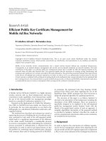
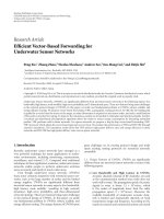
The cooperative area (CA) topology is shown in Figure 3.
As in the conventional cellular topology, one cell that is com-
posed of three sectors and the hexagonal area, which is com-
posed of three sectors which are served by three BSs, forms a
CA. Two MSs in the CA are served by three BSs simultane-
ously. In case of the 2BSs-2MSs case, two BSs which maintain
Jee Hyun Kim et al. 9
the strongest two links with MSs are chosen for downlink
transmission. The cell radius is 600 m and MSs are equally
distributed in the CA for every drop.
The transmit zero-forcing filter formula follows (3),
based on downlink channel information which is either per-
fect channel (pCh), or is provided by a downlink channel
estimation method which is shared by the BSs through a
prompt, error free backbone network (centralized CA de-
noted by cCA), or is acquired by the analog pilot retrans-
mission method (distributed CA denoted by dCA), or is cap-
tured and reconstructed by looking up an n bit codebook
(n bit channel quantization referred to as nbCQ). The cCA
case assumes that the system employs a time division duplex
(TDD) scheme and the backbone network connecting asso-
ciated BSs is delay free and error free. The downlink chan-
nel state information can be acquired by estimating uplink
channel by using uplink-downlink channel reciprocity, when
there exists a direct link between a BS and an MS. In simula-
tions, the uplink channel is assumed to be estimated by using
the uplink pilot signal. The nondirect link channel informa-
tion can be provided by BSs with direct links through prompt
data communication over the backbone network. In the ana-
log pilot retransmission method, the MS sends the received
pilot which pertains to the downlink channel state informa-
tion to all associated BSs over the uplink channel [1, 6]. In
this case, two pilots are required in the uplink. One is for
conveying the received pilot directly to the BSs (analog pilot
retransmission), and the other is for estimating the uplink
channel itself, which is necessary to compensate the retrans-
mitted pilot for the uplink channel influence so as to acquire
the downlink channel information. Therefore, these two pi-
lots should be adjacent in time and frequency. Since the esti-
mated version of the channel state information is used to peel
off distortions caused by the uplink channel from the retrans-
mitted pilot, this method is vulnerable to noise enhancement
effects.
The BSs are assumed to be aware of the large-scale fading
of the channel; and the channel quantization process (9)is
based on true channel information. (Some readers may find
a direct comparison between cCA and nbCQ inadequate in
the sense that cCA is based on the realistic channel estimation
method while nbCQ is based on the ideal channel knowledge.
However, the performance of the cCA case is provided here as
a mere reference for the mapping of the performance of the
proposed method in relation to an alternative method.) The
codebooks are acquired by the modified LBG VQ algorithm.
The feedback link is error free and delay free.
First, two proposals concerning the channel quantiza-
tion model are evaluated. One model (
H
d
j
,equation(9))
adopts the channel directional information only, and the
other (
H
j
,equation(8)) takes the channel magnitude in-
formation into account, as well as the channel directional
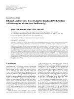
information. Figure 4 shows the CDF of the SINR for the
3BSs-2MSs case. The channel directional information-based
model (4bCDI, 5bCDI) performs closely to or in the low
SINR region even slightly better than the model which com-
bines the directional and magnitude information (4bCDMI,
5bCDMI). We assume that the BSs have access to the link
strengths (large-scale fading due to path loss and shadowing)
10
−1
10
0
Cumulative density
0 5 10 15 20 25 30
SINR (dB)
4bCDI
5bCDI
4bCDMI
5bCDMI
SINR@50% cdf
4bCDI: 13.8dB
5bCDI: 15.3dB
4bCDMI: 13.8dB
5bCDMI: 15.2dB
cdf of SINR for MS1, 3BS-2MS case (ZF),
R
cell
= 600 m,Urban Macro10 m/s
Figure 4: Performance comparison of channel quantization models
(4bCDI: 4-bit-channel directional information-based quantization;
5bCDI: 5-bit CDI; 4bCDMI: 4-bit channel directional/magnitude
information-based quantization; 5bCDMI: 5-bit CDMI).
for both cases, and the BSs have perfect knowledge of Σ
(S)
j
for the latter case. Simulation results indicate that the extra
channel magnitude information does not improve the SINR
performance in these cases. (We should be careful in inter-
preting the simulation results. We have simulated relatively
low-bit (4 and 5 bits) quantization cases. In this case, the
precision of the channel directional information is more rele-
vant to the system performance than the channel magnitude
information. The channel magnitude information can play
an important role for higher-bit quantization cases, where
the accuracy of the channel directional information is suffi-
ciently high that only the magnitude information can help
improve performance. In this paper, we focus on the lim-
ited feedback case in which the channel directional informa-
tion matters most.) Please note that in this paper the chan-
nel quantizer (CQ) or the subspace-based CQ refers to the
channel directional information-based model, unless other-
wise mentioned.
Figure 5 shows the CDF of the SINR for the 2BSs-2MSs
case. At 50% outage SINR, the 3-bit channel quantizer
(3bCQ) shows 7.8 dB gain over the analog pilot retransmis-
sion case (dCA) and it is only 0.1 dB away from the central-
ized CA (cCA). The channel matrix at MS j, H
j
(j = 1, 2), is
in this case a 2
×1 complex vector and this is represented by
a codebook of size 2
3
= 8. Compared with the channel quan-
tization method, the resource efficient dCA case requires 3-
pilot tones per MS in case of FDD. Therefore, the proposed
scheme performs much better than the pilot retransmission
method without requiring extra resources. Figure 6 deals
with simulation results of the 3BSs-2MSs case. The 3bCQ,
4bCQ, and 5bCQ cases have 3.2 dB, 5.0 dB, and 6.5 dB gains
over the dCA case, respectively. In this case, the proposed
10 EURASIP Journal on Advances in Signal Processing
10
−2
10
−1
10
0
Cumulative density
−20 −10 0 10 20 30 40
SINR (dB)
dCA
cCA
pCh
3bCQ
SINR@50% cdf
dCA: 7.4dB
cCA: 15.3dB
pCh: 23.7dB
3bCQ: 15.2dB
cdf of SINR for MS1, 2BS-2MS case (ZF),
R
cell
= 600 m,Urban Macro10 m/s
Figure 5: 2BSs-2MSs case simulation results (dCA: distributed CA;
cCA: centralized CA; pCh: perfect channel; 3bCQ: 3-bit CQ).
10
−2
10
−1
10
0
Cumulative density
−20 −10 0 10 20 30 40
SINR (dB)
dCA
cCA
pCh
3bCQ
4bCQ
5bCQ
SINR@50% cdf
dCA: 8.8dB
cCA: 16.9dB
pCh: 27.2dB
3bCQ: 12 dB
4bCQ: 13.8dB
5bCQ: 15.3dB
cdf of SINR for MS1, 3BS-2MS case (ZF),
R
cell
= 600 m,Urban Macro10 m/s
Figure 6: 3BSs-2MSs case simulation results (dCA: distributed CA;
cCA: centralized CA; pCh: perfect channel; 3bCQ: 3-bit CQ; 4bCQ:
4 bit CQ; 5bCQ: 5-bit CQ).
method still has a lot of room for improvement even though
the expected gain over the conventional method is not in-
significant. The gap between the proposed method and the
ideal case can be reduced by adopting a smart scheduling
strategy like user grouping which selects users with orthogo-
nal channel signatures so as to reduce interferences between
different users [18].
The proposed method is to quantize the channel matrix
based on the chordal distance, and the LBG VQ algorithm
is modified as such. Conventional VQ methods use the Eu-
clidean distance instead. Is the subspace-based method better
than the conventional method? A performance comparison
result is shown in Figure 7. The Euclidean distance-based CQ
(nbeCQ) adopts the Euclidean distance as a distance metric
for channel quantization. The simulation results show that
the subspace-based CQ has a substantial gain over the Eu-
clidean distance-based CQ. At 50% outage SINR, the 4bCQ
and5bCQoutperformthe4beCQand5beCQby2.9dBand
3.0 dB, respectively.
There exists another CQ method which exploits Givens
rotations [26]. This method allows us to represent the col-
umn space basis vectors U
(S)
∈ C
t×n
of the channel by
(2t
−1)n −n
2
real numbers. t = 3, n = 1 holds for the 3BSs-
2MSs case, and it requires 4 real number parameters (φ
1,2
,
φ
1,3
, θ
1,1
, θ
1,2
) for channel matrix construction. The per-
formance comparison result between the proposed method
and the Givens-rotation-based channel matrix decomposi-
tion method is shown in Figure 8. The Givens-rotation-based
method with n-bit feedback is denoted by nbGR. 4bGR allo-
cates 1 bit for each parameter, and 5bGR assigns 2, 2, 1, and 0
bit(s) for φ
1,2
, φ
1,3
, θ
1,1
,andθ
1,2
, respectively. (In this case, the
value of θ
1,2
is predefined and fixed.) At 50% outage SINR,
the 4bCQ case outperforms the 4bGR case by 2.5 dB, while
the 5bCQ case shows comparable performance to the 5bGR
case of which the computational complexity at MS is higher
than that of the 5bCQ case.
The performance of the combined codebook is shown
in Figure 9. Simulations have been performed for the 2BSs-
2MSs case. The combined codebooks are acquired by the
modified LBG VQ algorithm and the hierarchical codebook
construction method as described in Section 5.Thecom-
bined codebook of the n
c
-bit coarse and n
f
-bit fine feed-
backs with corresponding feedback periods τ
c
and τ
f
is de-
noted by n
c
+ n
f
bCQ ([τ
c
], [τ
f
]), where the unit of feed-
back period is the number of OFDM symbols: [τ]
= m,
when τ
= m·T
s
(T
s
= 71.37 μs). At 50% outage SINR, the
5-bit codebook case (5bCQ), which is generated by the hier-
archical codebook construction method, shows 11.8 dB and
3.9 dB gains over the analog pilot retransmission case (dCA)
and the centralized CA case (cCA), respectively. In this case,
the 5-bit feedback is being sent back for every symbol. The 3
+ 2-bit combined codebook with the empirically found opti-
mum feedback period pair ([τ
c
], [τ
f
])=(10,5), (3 + 2bCQ
1
)
is less than 0.1 dB away from the performance of the 5bCQ
case, even though some degradation is observed in the low
SINR region. In terms of the required resources, the 5bCQ
case requires 5 bits/symbol for feedback, while the 3 + 2bCQ
1
case needs only 0.7 bit/symbol. Thus, the 3 + 2-bit combined
codebook can achieve the performance of the 5-bit codebook
with negligible degradation by using just 14% of the feedback
resource.
We have tested the 3 + 2bCQ case with various subopti-
mum feedback periods, for example, (10,10) and (20,5), and
each case is denoted by the subscripts 2 and 3, respectively.
None of these cases outperforms the optimum case (10, 5),
and performance degradations are 0.7 dB and 0.8 dB for the
Jee Hyun Kim et al. 11
10
−2
10
−1
10
0
Cumulative density
−10 −5 0 5 1015202530
SINR (dB)
dCA
cCA
4bCQ
5bCQ
4beCQ
5beCQ
SINR@50% cdf
4bCQ: 13.8dB
5bCQ: 15.3dB
4beCQ: 10.9dB
5beCQ: 12.3dB
cdf of SINR for MS1, 3BS-2MS case (ZF),
R
cell
= 600 m,Urban Macro10 m/s
Figure 7: Performance comparison of the Euclidean distance-based
CQ and the subspace-based CQ (dCA: distributed CA; cCA: cen-
tralized CA; 4bCQ: 4 bit subspace-based CQ; 5bCQ: 5-bit subspace-
based CQ; 4beCQ: 4-bit Euclidean distance-based CQ; 5beCQ: 5-bit
Euclidean distance-based CQ).
longer fine feedback period case and the longer coarse feed-
back period case, respectively. The following points should
be noted with respect to simulation results.
(i) The optimum feedback period pair guarantees
thetargetperformance
In this case, ([τ
c
], [τ
f
]) = (10, 5) is the optimum feedback
period pair, and any other case with longer period results in
performance degradation. The task of finding an optimum
feedback period pair in an analytical way is an interesting
topic for future research.
(ii) The coarse feedback period is decisive
in the performance
Even though both τ
c
and τ
f
are important in deciding the
performance, τ
c
has a more profound impact than τ
f
, since
the coarse codebook is associated with the bigger encoding
region which entails a bigger error if the feedback infor-
mation is outdated. Both the (10,10) and (20,5) cases show
degradations in performance. The degradation of the (20,5)
case with a longer coarse feedback period is 0.1 dB which
is bigger than the (10,10) case with a longer fine feedback
period, even though the former requires 0.55 bit/symbol
feedback overhead while the latter needs 0.5 bit/symbol
overhead. In short, the (20,5) case performs worse than
the (10,10) case despite its higher feedback overhead, and
this performance degradation comes from the suboptimum
coarse feedback period.
10
−1
10
0
Cumulative density
0 5 10 15 20 25 30
SINR (dB)
dCA
cCA
4bCQ
5bCQ
4bGR
5bGR
SINR@50% cdf
4bCQ: 13.8dB
5bCQ: 15.3dB
4bGR: 11.3dB
5bGR: 15.3dB
cdf of SINR for MS1, 3BS-2MS case (ZF),
R
cell
= 600 m,Urban Macro10 m/s
Figure 8: Performance comparison of the Givens rotation-based
CQ and the subspace-based CQ (dCA: distributed CA; cCA: cen-
tralized CA; 4bCQ: 4-bit subspace-based CA; 5bCQ: 5-bit subspace-
based CQ; 4bGR: 4-bit Givens-rotation-based CQ; 5bGR: 5-bit
Givens-rotation-based CQ).
7. CONCLUSIONS
In this paper, we have investigated precoded MU-MIMO
systems with limited feedback. The subspace-based chan-
nel quantization method is proposed as a way of providing
BSs with downlink channel state information in the pres-
ence of interuser interference, which is applicable to the dis-
tributed COOPA systems as well as MU-MIMO systems. The
subspace-based channel quantizer improves the system per-
formance significantly, compared to the analog pilot retrans-
mission method with relatively small feedback overhead. We
also developed an efficient codebook construction algorithm
based on well-known LBG VQ by adopting the chordal dis-
tance and modifying the optimality criteria accordingly. The
codebooks generated by the proposed algorithm have better
distance properties than Grassmannian codebooks that are
currently available.
We have also proposed a feedback overhead reduction
scheme which makes use of the temporal correlation of the
channel. It constructs the codebook with a hierarchical struc-
ture so that the feedback index can be divided into two parts,
that is, a coarse feedback which points to the codebook in-
dex and a fine feedback which indicates the code index.
The resulting codebook is termed the combined codebook.
The simulation results suggest that we can save a significant
amount of feedback resources while maintaining the same
performance level as the case with fully loaded feedback. The
decision of the optimum feedback periods is an open issue
for future research.
12 EURASIP Journal on Advances in Signal Processing
10
−2
10
−1
10
0
Cumulative density
−10 −5 0 5 1015202530
SINR (dB)
dCA
cCA
pCh
5bCQ
3 + 2bCQ
1
(10, 5)
3 + 2bCQ
2
(10, 10)
3 + 2bCQ
3
(20, 5)
50% outage SINR
dCA: 7.4dB
cCA: 15.3dB
pCh: 23.7dB
5bCQ: 19.2dB
3 + 2bCQ
1
:19.1dB
3 + 2bCQ
2
:18.4dB
3 + 2bCQ
3
:18.3dB
cdf of SINR for MS1, 2BS-2MS case (ZF),
R
cell
= 600 m,Urban Macro10 m/s
Figure 9: Combined codebook simulation results for (n
c
+ n
f
b) =
(3 + 2b) case (dCA: distributed CA; cCA: centralized CA; pCh: per-
fect channel; 5bCQ: 5-bit CQ; 3 + 2bCQ
i
([τ
c
], [τ
f
]): 3-bit coarse
and 2-bit fine feedbacks with a feedback period pair ([τ
c
], [τ
f
]) ∈
{
(10, 5), (10,10),(20, 5)}).
APPENDIX
PROOF OF EQUATION (12)
First, we provide the formula which explains how the chordal
distance is related with the inner product, when it is used for
two unit norm vectors v
i
, v
j
,wherev
H
i
v
i
= v
H
j
v
j
= 1;
d
2
c
v
i
, v
j
=
1
√
2
v
i
v
H
i
−v
j
v
H
j
F
2
=
1
2
tr
v
i
v
H
i
−v
j
v
H
j
v
i
v
H
i
−v
j
v
H
j
H
=
1
2
tr
v
H
j
v
i
v
H
i
−v
j
v
H
j
v
i
v
H
i
−v
j
v
H
j
H
v
j
=
1
2
1 −v
H
j
v
i
v
H
i
v
j
)
=
1
2
1 −
v
i
, v
j
2
,
(A.1)
where
v
i
, v
j
=v
H
i
v
j
. The following property is used from
the first to the second line:
A
F
=
tr (AA
H
); and from
the third to the fourth line, the tr (
·) operation is omitted
since its argument has a scalar value. From (A.1), the decision
criterion in terms of the chordal distance can be formulated
as follows:
arg min d
c
v
i
, v
j
= arg max
v
i
, v
j
. (A.2)
On the other hand, the column space basis vector u
S
∈
C
N
tt
×1
of the channel vector h ∈ C
N
tt
×1
can be found as fol-
lows (the user index j is omitted for brevity):
h
= U
h
Σ
h
V
H
h
= v
h
σ
h
u
S
,(A.3)
where v
h
and σ
h
have scalar values and u
S
∈ C
N
tt
×1
.The
rightmost form is an “economy size” version of the SVD,
where v
h
is in effect the same as V
h
(size: 1 × 1), and σ
h
is
the only nonzero singular value in Σ
h
. The followings holds:
σ
h
=h
2
and v
h
∈{+1, −1}, since h is a vector. Therefore,
u
S
can be expressed in terms of the directional vector of the
channelasfollows:
u
S
= v
h
h
h
2
= v
h
v,(A.4)
where v
= h/h
2
is the directional vector of the channel.
Since v
h
decides the sign only, the following criterion holds:
h = arg min
c
i
∈C
d
c
u
S
, c
i
=
arg max
c
i
∈C
v, c
i
. (A.5)
Therefore, the chordal distance-based channel quantization
criterion (9) can be simplified to the inner product-based cri-
terion (12).
ACKNOWLEDGMENT
Part of this work was presented at the International ITG/IEEE
Workshop on Smart Antennas (WSA’07), Vienna, Austria,
February 2007.
REFERENCES
[1] W. Zirwas, J. H. Kim, V. Jungnickel, et al., “Distributed orga-
nization of cooperative antenna systems,” in Distributed An-
tenna Systems: Open Architecture for Future Wireless Commu-
nications, H. Hu, Y. Zhang, and J. Luo, Eds., chapter 10, Auer-
bach Publications, Boca Raton, Fla, USA, June 2007.
[2] M. K. Karakayali, G. J. Foschini, and R. A. Valenzuela, “Net-
work coordination for spectrally efficient communications in
cellular systems,” IEEE Wireless Communications,vol.13,no.4,
pp. 56–61, 2006.
[3] M. K. Karakayali, G. J. Foschini, R. A. Valenzuela, and R. D.
Yates,“Onthemaximumcommonrateachievableinacoordi-
nated network,” in Proceedings of the IEEE International Con-
ference on Communications (ICC ’06), vol. 9, pp. 4333–4338,
Istanbul, Turkey, June 2006.
[4] G. J. Foschini, K. Karakayali, and R. A. Valenzuela, “Coor-
dinating multiple antenna cellular networks to achieve enor-
mous spectral efficiency,” IEE Proceedings Communications,
vol. 153, pp. 548–555, 2006.
[5] G. J. Foschini, H. C. Huang, M. K. Karakayali, R. A. Valen-
zuela, and S. Venkatesan, “The value of coherent base station
coordination,” in Proceedings of the 39th Annual Conference on
Information Sciences and Systems (CISS ’05), The Johns Hop-
kins University, Baltimore, Md, USA, March 2005.
[6] W. Zirwas, E. Schulz, J. H. Kim, V. Jungnickel, and M. Schu-
bert, “Distributed organization of cooperative antenna sys-
tems,” in Proceedings of 12th European Wireless Conference,
Athens, Greece, April 2006.
Jee Hyun Kim et al. 13
[7] D. J. Love, R. W. Heath Jr., and T. Strohmer, “Grassman-
nian beamforming for multiple-input multiple-output wire-
less systems,” IEEE Transactions on Information Theory, vol. 49,
no. 10, pp. 2735–2747, 2003.
[8] B. M. Hochwald, T. L. Marzetta, T. J. Richardson, W. Sweldens,
and R. Urbanke, “Systematic design of unitary space-time con-
stellations,” IEEE Transactions on Information Theory, vol. 46,
no. 6, pp. 1962–1973, 2000.
[9] J. C. Roh and B. D. Rao, “Vector quantization techniques for
multiple-antenna channel information feedback,” in Proceed-
ings of the International Conference on Signal Processing and
Communications (SPCOM ’04), pp. 402–406, Banalore, India,
December 2004.
[10] J. C. Roh and B. D. Rao, “Design and analysis of MIMO spatial
multiplexing systems with quantized feedback,” IEEE Transac-
tions on Signal Processing, vol. 54, no. 8, pp. 2874–2886, 2006.
[11] D. J. Love, R. W. Heath Jr., W. Santipach, and M. L. Honig,
“What is the value of limited feedback for MIMO channels?”
IEEE Communications Magazine, vol. 42, no. 10, pp. 54–59,
2004.
[12] N. Jindal, “Finite rate feedback MIMO broadcast channels,”
in Proceedings of the Workshop on Information Theory and Its
Applications (ITA ’06), San Diego, Calif, USA, February 2006.
[13] J. A. Nossek, M. Joham, and W. Utschick, “Transmit pro-
cessing in MIMO wireless systems,” in Proceedings of the 6th
IEEE Circuits and Systems Symposium on Emerging Technolo-
gies: Frontiers of Mobile and Wireless Communication (CAS-
SET ’04), vol. 1, pp. 18–23, Shanghai, China, May-June 2004.
[14] M. Tomlinson, “New automatic equaliser employing modulo
arithmetic,” Electronics Letters, vol. 7, no. 5-6, pp. 138–139,
1971.
[15] H. Harashima and H. Miyakawa, “Matched-transmission
technique for channels with intersymbol interference,” IEEE
Transactions on Communications, vol. 20, no. 4, pp. 774–780,
1972.
[16] Q. H. Spencer, A. L. Swindlehurst, and M. Haardt, “Zero-
forcing methods for downlink spatial multiplexing in mul-
tiuser MIMO channels,” IEEE Transactions on Signal Process-
ing, vol. 52, no. 2, pp. 461–471, 2004.
[17] V. Stankovic and M. Haardt, “Multi-user MIMO downlink
precoding for users with multiple antennas,” in Proceedings
of the 12th Meeting of the Wireless World Research Forum
(WWRF ’04), Toronto, Ontario, Canada, November 2004.
[18] T. Yoo and A. Goldsmith, “On the optimality of multiantenna
broadcast scheduling using zero-forcing beamforming,” IEEE
Journal on Selected Areas in Communications,vol.24,no.3,pp.
528–541, 2006.
[19] D. J. Love and R. W. Heath Jr., “Limited feedback unitary pre-
coding for spatial multiplexing systems,” IEEE Transactions on
Information Theory, vol. 51, no. 8, pp. 2967–2976, 2005.
[20] S. Zhou and B. Li, “BER criterion and codebook construc-
tion for finite-rate precoded spatial multiplexing with linear
receivers,” IEEE Transactions on Signal Processing, vol. 54, no. 5,
pp. 1653–1665, 2006.
[21] T. Yoo, N. Jindal, and A. Goldsmith, “Finite-rate feedback
MIMO broadcast channels with a large number of users,” in
Proceedings of the IEEE International Symposium on Informa-
tion Theory (ISIT ’06), pp. 1214–1218, Seattle, Wash, USA, July
2006.
[22] Y. Linde, A. Buzo, and R. M. Gray, “An algorithm for vector
quantizer design,” IEEE Transactions on Communications,pp.
702–710, 1980.
[23] D. J. Love, “Personal webpage on Grassmannian subspace
packing,” />[24] K. Huang, B. Mondal, R. W. Heath Jr., and J. G. Andrews,
“Limited feedback for temporally-correlated channels: feed-
back rate and delay,” to appear in IEEE Transactions on Infor-
mation Theory, />=oai:arXiv
.org:cs/0606022.
[25] D. S. Baum, J. Salo, M. Milojevic, P. Ky
¨
osti, and J. Hansen,
“MATLAB implementation of the interim channel model
for Beyond-3G systems (SCME),” .fi/Units/
Radio/scm/.
[26] J. C. Roh and B. D. Rao, “An efficient feedback method for
MIMO systems with slowly time-varying channels,” in Pro-
ceedings of the IEEE Wireless Communications and Networking
Conference (WCNC ’04), vol. 2, pp. 760–764, Atlanta, Ga, USA,
March 2004.