Báo cáo hóa học: " Research Article Zero-Forcing and Minimum Mean-Square Error Multiuser Detection in Generalized Multicarrier " docx
Bạn đang xem bản rút gọn của tài liệu. Xem và tải ngay bản đầy đủ của tài liệu tại đây (887.26 KB, 13 trang )
Hindawi Publishing Corporation
EURASIP Journal on Wireless Communications and Networking
Volume 2008, Article ID 541410, 13 pages
doi:10.1155/2008/541410
Research Article
Zero-Forcing and Minimum Mean-Square Error Multiuser
Detection in Generalized Multicarrier DS-CDMA Systems for
Cognitive Radio
Lie-Liang Yang
1
and Li-Chun Wang
2
1
School of Electronics and Computer Science, University of Southampton SO17 1BJ, UK
2
Department of Communications Engineering, National Chiao Tung University, Hsinchu 300, Taiwan
Correspondence should be addressed to Lie-Liang Yang,
Received 30 April 2007; Revised 15 September 2007; Accepted 17 November 2007
Recommended by Luc Vandendorpe
In wireless communications, multicarrier direct-sequence code-division multiple access (MC DS-CDMA) constitutes one of the
highly flexible multiple access schemes. MC DS-CDMA employs a high number of degrees-of-freedom, which are beneficial to
design and reconfiguration for communications in dynamic communications environments, such as in the cognitive radios. In
this contribution, we consider the multiuser detection (MUD) in MC DS-CDMA, which motivates lowcomplexity, high flexibility,
and robustness so that the MUD schemes are suitable for deployment in dynamic communications environments. Specifically, a
range of low-complexity MUDs are derived based on the zero-forcing (ZF), minimum mean-square error (MMSE), and interfer-
ence cancellation (IC) principles. The bit-error rate (BER) performance of the MC DS-CDMA aided by the proposed MUDs is
investigated by simulation approaches. Our study shows that, in addition to the advantages provided by a general ZF, MMSE, or
IC-assisted MUD, the proposed MUD schemes can be implemented using modular structures, where most modules are indepen-
dent of each other. Due to the independent modular structure, in the proposed MUDs one module may be reconfigured without
yielding impact on the others. Therefore, the MC DS-CDMA, in conjunction with the proposed MUDs, constitutes one of the
promising multiple access schemes for communications in the dynamic communications environments such as in the cognitive
radios.
Copyright © 2008 L L. Yang and L C. Wang. This is an open access article distributed under the Creative Commons Attribution
License, which permits unrestricted use, distribution, and reproduction in any medium, provided the original work is properly
cited.
1. INTRODUCTION
Recently, there has been an increasing interest in cognitive
and software defined radios in both the research and industry
communities, as is evidenced, for example, by [1–4]aswell
as by the references in them. The cognitive radio equipped
with flexible software defined architectures aims at the intel-
ligent wireless communications, which is capable of sensing
its environment, learning from the environment, and adap-
tively responding to the environment, in order to achieve
high-efficiency and high-flexibility wireless communications
anytime, anywhere, and in anyway. In cognitive and software
defined radios, a highly efficient and flexible multiple access
scheme that is suitable for online reconfigurations is highly
important.
In broadband wireless communications, multicarrier
code-division multiple access (CDMA) scheme has received
wide attention in recent years [5–12]. This is because mul-
ticarrier CDMA schemes employ a range of advantages,
which include low intersymbol interference (ISI) due to
invoking serial-to-parallel (S-P) conversion at the trans-
mitter, low implementation complexity of carrier modula-
tion/demodulation for the sake of using fast Fourier trans-
form (FFT) techniques, and so forth. In multicarrier CDMA
systems, frequency diversity may be achieved by repeating the
transmitted signal in the frequency (F) domain with the aid
of several subcarriers [5, 7–9]; multiple transmit/receive an-
tennas may be deployed, in order to achieve the spatial di-
versity [6, 13] and/or to increase the capacity of the mul-
ticarrier CDMA systems [14]. In comparison with the pure
DS-CDMA using only time (T) domain spreading and pure
MC-CDMA using only F domain spreading, it has been
demonstrated that the multicarrier direct sequence CDMA
(MC DS-CDMA) has the highest flexibility [5, 15] and the
2 EURASIP Journal on Wireless Communications and Networking
Serial-to-parallel
converter
b
(k)
q
b
(k)
2
c
k
(t)cos(2πf
12
t)
cos(2πf
11
t)
cos(2πf
1p
t)
×
×
×
×
Symbol duration T
s
= qT
b
b
(k)
1
.
.
.
.
.
.
.
.
.
Data
T
b
1
2
p
S
k
(t)
U
= pq
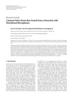
Figure 1: Transmitter schematic block diagram of the kth user in the generalized MC DS-CDMA systems.
highest number of degrees-of-freedom [5] for reconfigura-
tions; these properties may render the MC DS-CDMA a
versatile multiple access scheme that is suitable for cogni-
tive and software-defined radios. Note that the orthogonal
frequency-division multiplexing, code-division multiplexing
(OFDM-CDM) scheme [16], which employs both T domain
and F domain spreadings, may also constitute a high-flexible
scheme that is suitable for reconfigurations.
Multiuser detection (MUD) in the context of various
multicarrier CDMA schemes has been widely investigated,
as seen, for example, in [17–21]. This contribution mo-
tivates low-complexity, high-reliability, and low-sensitivity
MUD in the MC DS-CDMA operated under the cogni-
tive radio. This is because in a highly dynamic wireless
communications environment, such as in cognitive radio,
low-complexity, high-reliability, and robustness to imper-
fect knowledge due to, for example, channel estimation er-
ror are extremely important. Specifically, in this contri-
bution we investigate the zero-forcing MUD (ZF-MUD)
and minimum mean-square error MUD (MMSE-MUD) in
the MC DS-CDMA systems. Various alternatives for im-
plementation of the ZF-MUD and MMSE-MUD are pro-
posed. To be more specific, in this contribution three types
of ZF-MUDs and four types of MMSE-MUDs are pro-
posed. The ZF-MUDs include the optimum ZF-MUD (OZF-
MUD), suboptimum ZF-MUD (SZF-MUD), as well as the
interference cancellation aided suboptimum ZF-MUD (SZF-
IC). The MMSE-MUDs include the optimum MMSE-MUD
(OMMSE-MUD), suboptimum MMSE-MUD type I and II
(SMMSE-MUD-I, SMMSE-MUD-II) and the interference
cancellation aided suboptimum SMMSE-MUD-II (SMMSE-
IC). From our study it can be shown that in MC DS-CDMA
systems both the ZF-MUDs and MMSE-MUDs have the
modular structures that are beneficial to implementation and
reconfiguration. Furthermore, in this contribution the bit-
error rate (BER) performance of the MC DS-CDMA systems
employing the proposed various MUDs is investigated by
simulations. From our study and simulation results, it can be
shown that among these MUDs, the SZF-MUD, SZF-IC, and
the SMMSE-MUD-II, SMMSE-IC, constitute the promising
MUD schemes that can provide the following advantages.
(i) Low complexity. The complexity of these MUDs is
in the order of the single-user matched-filter- (MF-)
based detector, when the active users in the MC DS-
CDMA system are maintained unchanged.
(ii) High efficiency. Both SZF-MUD and SMMSE-MUD-
II are capable of mitigating efficiently the multiuser
interference (MUI), although their achievable BER
performance is worse than that of their correspond-
ing OZF-MUD and OMMSE-MUD. However, when
an IC-stage is invoked following the SZF-MUD or
SMMSE-MUD-II, the SZF-IC or SMMSE-IC is ca-
pable of achieving the near single-user BER bound
achieved by the MC DS-CDMA supporting single-
user.
(iii) Robust to imperfect channel knowledge. In the above
four types of MUDs, the time-variant channel impulse
responses (CIRs) are only invoked in linear operations
as in MF-assisted detection. No channel-dependent
matrices need to be inverted. Hence, we can be implied
that these MUDs should have a similar sensitivity as
the MF detector to the channel estimation errors.
(iv) High-flexibility. Due to the modular structures and
the relative independence among the modules, these
MUDs are highly flexible. For example, if some of the
subcarriers are sensed with high interference temper-
ature, these MUD algorithms can be readily modified
to adapt the environment, as can be seen in our forth-
coming discourses.
The remainder of this contribution is organized as fol-
lows. Section 2 describes the MC DS-CDMA system in the
context of its transmitter and receiver models. In this sec-
tion, the desirable representations for the observations at the
receiver are also provided. Section 3 derives the ZF-MUDs,
while Section 4 considers the MMSE-MUDs. In Section 6 the
simulation results are provided, while, finally, in Section 7 we
present our conclusions.
L L. Yang and L C. Wang 3
2. SYSTEM DESCRIPTION
In this section, the considered MC DS-CDMA system is
described in the context of the transmitted signal, channel
model, receiver, as well as the representation of the received
discrete signals. Let us first describe the transmitter of the
MC DS-CDMA system.
2.1. Transmitted signals
The transmitter schematic diagram of the kth user in the
considered MC DS-CDMA is shown in Figure 1. As shown
in Figure 1 the initial data stream having a bit duration of
T
b
is first serial-to-parallel (S-P) converted to q number of
lower-rate substreams. Hence, the new bit duration after the
S-P conversion or the symbol duration is T
s
= qT
b
.Eachof
the q lower-rate substreams is spread by c
k
(t)ofthekth user’s
signature sequence. As shown in Figure 1, each of the q sub-
streams is transmitted by p number of subcarriers, in order
for achieving a pth order frequency diversity. Hence, the total
number of subcarriers required by the MC DS-CDMA sys-
tem is U
= pq.BasedonFigure 1, the transmitted signal of
user k can be expressed as
s
k
(t) =
q
i=1
p
j=1
2P
p
b
(k)
i
(t)c
k
(t)cos
2πf
ij
t + φ
(k)
ij
,
k
= 1, 2, ,K,
(1)
where P is the transmitted power of each substream, b
(k)
i
(t) =
∞
n=−∞
b
(k)
i
[n]P
T
s
(t − nT
s
)(i = 1, , q) represents the bi-
nary data of the ith substream, where b
(k)
i
[n]isassumedto
be a random variable taking values of +1 or
−1withequal
probability, while P
τ
(t) represents the rectangular waveform.
In (1) c
k
(t) represents the spreading code assigned to the
kth user, which is the same for all the U
= pq number of
subcarriers. The spreading sequence c
k
(t) can be expressed
as c
k
(t) =
∞
j=−∞
c
(k)
j
ψ(t − jT
c
), where c
(k)
j
assumes values
of +1 or
−1, while ψ(t) is the T domain chip waveform of
the spreading sequence, which is defined over the interval
[0, T
c
) and normalized to
T
c
0
ψ
2
(t)dt = T
c
. Furthermore,
N
e
= T
s
/T
c
= qT
b
/T
c
is defined as the spreading factor on
each of the subcarriers. Finally, in (1) φ
(k)
ij
represents the ini-
tial phase associated with the carrier modulation with respect
to the subcarrier determined by (i, j)in(1).
In the considered MC DS-CDMA, we assume that the
subcarrier signals are configured so that the subcarrier sig-
nals are orthogonal with each other at the chip-level. This
condition can be achieved, for example, by letting the spacing
between two adjacent subcarriers be Δ
= 1/T
c
or Δ = 2/T
c
[7, 8, 11]. We assume that the bandwidth of each subcarrier
signal is configured to be sufficiently narrow in comparison
with the coherence bandwidth of the wireless channel, so that
each subcarrier signal experiences flat fading. As shown in
[5], this configuration can be implemented by changing the
total number of subcarriers qp, the spacing between two ad-
jacent subcarriers and/or the number of bits q invoked in the
S-P conversion. Furthermore, we assume that the subcarri-
ers are arranged in such a way that the subcarriers conveying
the same data bit, as shown in Figure 1,areseparatedasfar
away as possible, in order to achieve possibly the highest F
domain diversity. Note that, in our simulations we assume
for simplicity that the subcarriers conveying the same data
bit experience independent fading.
Let us assume that the MC DS-CDMA system supports
K number of users, which communicate with one com-
mon base-station (BS) synchronously. The average power re-
ceived from each user at the BS is also assumed to be the
same. Furthermore, we assume that the MC DS-CDMA sig-
nals experience frequency-selective Rayleigh fading, but each
of the subcarrier signals experiences flat Rayleigh fading.
Consequently, when K signals obeying the form of (1)are
transmitted over the above-mentioned channels, the received
baseband equivalent signal at the BS can be expressed as
R(t)
=
K
k=1
q
i=1
p
l=1
2P
p
h
(k)
il
b
(k)
i
(t)c
k
(t)exp
j2πf
il
t
+ n(t),
(2)
where h
(k)
il
represents the channel gain with respect to the ilth
subcarrier of the kth user, while n(t) is the complex base-
band equivalent Gaussian noise, which has mean-zero and a
single-sided power spectral-density of N
0
per real dimension.
Note that, without loss of any generality, in (2) the initial
phases of the subcarriers have been absorbed into the chan-
nel gains.
2.2. Representation of the received signal
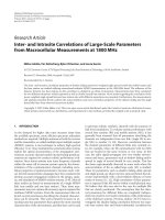
The receiver structure for detection of the MC DS-CDMA
signal is shown in Figure 2. The receiver first executes the
multicarrier demodulation, which can usually be imple-
mented by the FFT techniques [22]. Following the multi-
carrier demodulation, a chip waveform matched-filter (MF)
with the T domain impulse response ψ
∗
(T
c
− t)isem-
ployed by each of the subcarrier branches. Finally, as shown
in Figure 2, the chip waveform MFs outputs are sampled at
the chip-rate in order to provide the discrete observations for
detection.
According to Figure 2, it can be shown that the nth obser-
vation with respect to the first transmitted MC DS-CDMA
symbol and the uvth subcarrier can be expressed as
y
uv,n
=
2PN
e
T
c
−1
(n+1)T
c
nT
c
R(t)exp
−
j2πf
uv
t
ψ
∗
(t)dt,
n
= 0, 1, ,N
e
− 1, v = 1, 2, , p, u = 1, 2, , q.
(3)
Upon substituting (2) into (3) and using the assumption that
the subcarrier signals are orthogonal at the chip-level, it can
be shown that y
uv,n
can be expressed as
y
uv,n
=
K
k=1
1
N
e
p
h
(k)
uv
c
(k)
n
b
(k)
u
[0]+N
uv,n
, n = 0, 1, , N
e
− 1,
v
= 1, 2, , p, u = 1, 2, , q,
(4)
4 EURASIP Journal on Wireless Communications and Networking
R(t)
×
exp(−j2πf
uv
t)
(n
= 0, 1, , N
e
− 1)
Chip-waveform
matched-filter
ψ
∗
(T
c
−t)
nT
c
1
···
···
uv
qp
Detection
algorithm
Data
output
Figure 2: The receiver block diagram of the MC DS-CDMA systems using time-limited chip waveforms.
where N
uv,n
represents the Gaussian noise given by
N
uv,n
=
2PN
e
T
c
−1
(n+1)T
c
nT
c
n(t)exp
− j2πf
uv
t
ψ
∗
(t)dt
(5)
which is Gaussian distributed with mean-zero and a variance
of σ
2
/2 = N
0
/2E
b
per real dimension.
From (4) we notice that there is no inter-carrier interfer-
ence (ICI), yielding that there is no interference among the
bits transmitted on different subcarriers. Hence, it is suffi-
cient for us to consider the detection of the K bits—each of
which is transmitted by one of the K users—transmitted on
the same p number of subcarriers. Specifically, in our forth-
coming discourse we consider the detection of the uth bits of
the K users, which are transmitted by the subcarriers indexed
by f
u1
, f
u2
, , f
up
.
Let us now represent the observations in (4)insomede-
sired forms, so that they can be conveniently applied in our
forthcoming derivations. Let us define
y
uv
=
y
uv,0
, y
uv,1
, , y
uv,N
e
−1
T
,
n
uv
=
N
uv,0
, N
uv,1
, , N
uv,N
e
−1
T
,
c
k
=
1
N
e
c
(k)
0
, c
(k)
1
, , c
(k)
N
e
−1
T
.
(6)
Then, y
uv
can be represented
y
uv
=
K
k=1
1
√
p
h
(k)
uv
c
k
b
(k)
u
[0] + n
uv
, p = 1, 2, , p,
u
= 1, 2, , q.
(7)
Let us define
y
u
=
y
T
u1
, y
T
u2
, , y
T
up
T
,
n
u
=
n
T
u1
, n
T
u2
, , n
T
up
T
,
h
ku
=
1
√
p
h
(k)
u1
, h
(k)
u2
, , h
(k)
up
T
.
(8)
Then, y
u
can be expressed as
y
u
=
K
k=1
h
ku
⊗ c
k
b
(k)
u
+ n
u
, u = 1, 2, , q,
(9)
where
⊗ represents the Kronecker product [23]operation.
Furthermore, if we define
b
u
=
b
(1)
u
[0], b
(2)
u
[0], , b
(K)
u
[0]
T
,
C
=
c
1
, c
2
, , c
K
,
H
u
=
h
1u
, h
2u
, , h
Ku
.
(10)
Then, (9) can alternatively be represented as
y
u
=
H
u
C
b
u
+ n
u
, u = 1, 2, , q,
(11)
where (H
u
C) represents the Khatri-Rao product between
H
u
and C.
In summary, in (11) y
u
is a pN
e
-length observation vec-
tor, H
u
is a (p × K)-dimensional matrix due to the fading
channels experienced by the subcarrier signals of the K users,
C is a (N
e
×K) matrix contributed by the spreading sequences
of the K users, b
u
contains K binary bits to be detected and,
finally, n
u
is the pN
e
-length Gaussian noise vector distributed
associated with mean zero and a covariance matrix of σ
2
I
pN
e
,
where I
pN
e
is a (pN
e
× pN
e
) identity matrix.
Additionally, it can be shown that (7) can also be written
as
y
uv
=CH
uv
b
u
+n
uv
, v = 1, 2, , p, u=1, 2, , q, (12)
where H
uv
is a diagonal matrix expressed as
H
uv
=
1
√
p
diag
h
(1)
uv
, h
(2)
uv
, , h
(K)
uv
.
(13)
As shown in (11), the spreading code matrix C is certain
once the users’ spreading codes are given. The matrix H
u
de-
noting the CIRs is known, once the channels are estimated.
Let us now consider the multiuser detection in the MC DS-
CDMA, which are derived based on (9), (11), or (12).
3. ZERO-FORCING MULTIUSER DETECTION
In this section, we consider the ZF-MUDs in the MC DS-
CDMA system. These ZF-MUDs are capable of removing
fully the MUI at the cost of enhancing the background noise
[24]. We assume for ZF-MUD that the BS receiver employs
the knowledge about C and H
u
. Let us consider first the op-
timum ZF-MUD, that is, the OZF-MUD.
3.1. Optimum zero-forcing multiuser detection
The OZF-MUD is derived based on (11) by jointly treating
the observations without regarding to the specific subcar-
riers. The OZF-MUD is capable of achieving a better BER
L L. Yang and L C. Wang 5
y
qp
y
up
y
u2
y
u1
y
11
Matched-filter
H
H
qp
C
T
Matched-filter
H
H
up
C
T
Matched-filter
H
H
u2
C
T
Matched-filter
H
H
u1
C
T
Matched-filter
H
H
11
C
T
Zero-forcing
(H
H
u
H
u
R
c
)
−1
Symbol 1
Symbol u
Symbol q
x
q
x
u
x
1
.
.
.
.
.
.
···
···
···
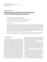
Figure 3: Schematic block diagram for implementation of the OZF-MUD in MC DS-CDMA systems.
performance than the SZF-MUD that will be derived later
in Section3.2. However, its implementational complexity is
much higher than that of the SZF-MUD.
The decision variable vector for b
u
in the context of the
OZF-MUD can be expressed as
z
u
= W
H
u
y
u
, u = 1, 2, , q,
(14)
where, according to (11), it can be readily shown that the
weight matrix W
u
in ZF sense can be denoted as
W
u
=
H
u
C
H
u
C
H
H
u
C
−1
.
(15)
Using the property of (H
u
C)
H
(H
u
C) = (H
H
u
H
u
C
T
C)
[23], where
represents the Hadamard product operation
[25], the above equation can be denoted as
W
u
=
H
u
C
H
H
u
H
u
R
c
−1
,
(16)
where R
c
= C
T
C.
In (16), the matrix required to be inverted, that is,
(H
H
u
H
u
R
c
), is a (K × K)matrix,whichmaybeefficiently
computed due to the following reasons. Firstly, R
c
is a (K ×K)
time-invariant matrix, which can be computed once for all.
Secondly, although H
H
u
H
u
is a (K × K) time-variant matrix,
it is only required to be updated at the level of fading rate of
the wireless channels experienced by the subcarrier signals.
Finally, the Hadamard product between H
H
u
H
u
and R
c
con-
stitutes K
2
straightforward complex multiplications.
Upon applying (16) into (14), the decision variable vec-
tor can be written as
z
u
=
H
H
u
H
u
R
c
−1
H
u
C
H
y
u
.
(17)
In (17), (H
u
C)
H
y
u
can be expressed as
H
u
C
H
y
u
=
h
1u
⊗ c
1
h
2u
⊗ c
2
···
h
Ku
⊗ c
K
H
⎡
⎢
⎢
⎢
⎢
⎣
y
u1
y
u2
.
.
.
y
up
⎤
⎥
⎥
⎥
⎥
⎦
=
p
v=1
H
H
uv
C
T
y
uv
,
(18)
where H
uv
hasbeendefinedin(13)andy
uv
is given by (12).
Therefore, when substituting (18) into (17), we obtain
z
u
=
H
H
u
H
u
R
c
−1
p
v=1
H
H
uv
C
T
y
uv
, u = 1, 2, , q.
(19)
Equation (19) shows that the OZF-MUD for b
u
can be
divided into p MF operations corresponding to the p num-
ber of subcarriers conveying b
u
and one ZF operation, which
multiplies a (K
×K)matrixof[(H
H
u
H
u
R
c
)]
−1
on the MFs’
outputs. In summary, the OZF-MUD can be implemented
by the schematic block diagram as shown in Figure 3.
3.2. Suboptimum zero-forcing multiuser detection
In the considered MC DS-CDMA, each subcarrier signal is
constituted by K DS-CDMA signals belonging to K users
and a data bit of a given user is conveyed by p subcarriers. In
this type of MC DS-CDMA, the linear MUD may be imple-
mented first by carrying out the MUD associated with each
of the subcarriers. After the MUD at the subcarrier level, the
subcarrier signals conveying the same data bit are coherently
6 EURASIP Journal on Wireless Communications and Networking
y
qp
y
up
y
u2
y
u1
y
11
Zero-forcing
R
−1
c
C
T
Zero-forcing
R
−1
c
C
T
Zero-forcing
R
−1
c
C
T
Zero-forcing
R
−1
c
C
T
Zero-forcing
R
−1
c
C
T
H
H
11
H
H
u1
H
H
u2
H
H
up
H
H
qp
x
q
x
u
x
1
MRC
···
···
···
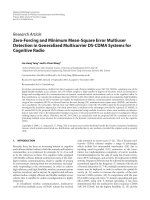
Figure 4: Schematic block diagram for implementation of the SZF-MUD in MC DS-CDMA systems.
combined in order to form a final decision variable. Specif-
ically, when the SZF-MUD following this design philosophy
is considered, for the uth data vector b
u
transmitted by the K
users, the decision variable vector in the context of the uvth
subcarrier can be formed as
z
uv
= W
H
uv
y
uv
, u = 1, 2, , q; v = 1, 2, , p,
(20)
where W
uv
is a (N
e
× K) weight matrix for processing the
observation vector y
uv
of (12). After the MUD operation of
(20), the p subcarrier signals conveying b
u
are then coher-
ently combined to form the final decision variable, which can
be expressed as
z
u
=
p
v=1
T
H
uv
z
uv
, u = 1, 2, , q,
(21)
where the matrix T
uv
is a postprocessing matrix carrying out
the coherent combining, such as the maximal ratio combin-
ing (MRC).
It can be shown that, for the SZF-MUD using MRC, the
weight matrix in ZF sense and the postprocessing matrix can
be chosen as
W
uv
= C
C
T
C
−1
= CR
−1
c
, T
uv
= H
uv
.
(22)
Upon substituting (12), (20), and (22) into (21), the decision
variable vector for b
u
can be expressed as
z
u
=
p
v=1
T
H
uv
R
−1
c
C
T
y
uv
=
p
v=1
H
H
uv
H
uv
b
u
+
p
v=1
H
H
uv
R
−1
c
C
T
n
uv
, u=1,2, , q.
(23)
Note that since H
uv
defined in (13) is a diagonal matrix, ex-
plicitly, the SZF-MUD is capable of removing fully the MUI
and achieving a F domain diversity order of p.
In summary, the SZF-MUD can be implemented by the
schematic block diagram of Figure 4. As shown in (22)and
Figure 4, the weight matrix W
uv
fortheSZF-MUDistime-
invariant and is common to any of the qpsubcarriers. Hence,
it can be computed “once for all,” provided that the active
users maintain unchanged. In this case, the proposed SZF-
MUD having the processing matrices in (22) in fact has an
implementational complexity that is similar to the single-
user MF receiver. However, if the state of the active users
changes rapidly, the weight matrix W
uv
for the SZF-MUD
is also required to be updated correspondingly. In this sce-
nario, the proposed SZF-MUD having the processing matri-
ces in (22) will have a higher complexity than the single-user
MF receiver. Furthermore, when comparing Figure 4 with
Figure 3, we can see that the time-variant channel matrices
are invoked in the inverse operations in Figure 3 for the OZF-
MUD, but not invoked in the inverse operations in Figure 4
for the SZF-MUD. In Figure 4 the channel-dependent time-
variant matrices are only invoked in the linear processing as
in the single-user MF-based receiver. Hence, we may be im-
plied that the SZF-MUD will be more robust than the OZF-
MUD to the channel estimation errors. However, as our sim-
ulation results in Section 6 shown, the error performance of
the MC DS-CDMA using the SZF-MUD is much worse than
that of the MC DS-CDMA using the OZF-MUD.
Figures 3 and 4 show that both the OZF-MUD and SZF-
MUD have the modular structures. In Figure 3 the oper-
ations in the MF modular components are subcarrier-by-
subcarrier independent. The ZF operations for the q bits of a
user are bit-by-bit independent but subcarrier-by-subcarrier
dependent for a given bit. By contrast, in Figure 4 the ZF
L L. Yang and L C. Wang 7
operations are subcarrier-by-subcarrier independent. Except
the sum operation, the MRC operations are also subcarrier-
by-subcarrier independent. Explicitly, the modular struc-
tures of the OZF-MUD and SZF-MUD as shown in Figures 3
and 4 are beneficial to implementation and reconfiguration
in practice. For example, in a dynamic communications envi-
ronment such as in cognitive radio, when certain frequency
bands are occupied and some of the subcarriers in the MC
DS-CDMA are sensed having high interference temperature,
the OZF-MUD in Figure 3 and the SZF-MUD in Figure 4
can be correspondingly reconfigured in order to adapt to
the changed environment. Specifically, for the OZF-MUD as
shown in Figure 3, the subcarrier branches having the high
interference temperature can be directly deleted from the re-
ceiver. However, the matrices implementing the ZF opera-
tions must be updated by removing the CIRs corresponding
to the subcarriers having the high interference temperature.
By contrast, the SZF-MUD as shown in Figure 4 can be up-
dated simply by deleting the subcarrier branches having the
high interference temperature, that is, by setting the corre-
sponding observation vectors in the form of y
uv
to the zero
vectors.
3.3. Interference cancellation aided
suboptimum zero-forcing
The error performance of the MC DS-CDMA using the SZF-
MUD may be significantly enhanced by employing a stage of
IC following the SZF-MUD, yielding the SZF-IC. Our simu-
lation results in Section 6 show that the MC DS-CDMA using
SZF-IC is capable of achieving the near single-user BER per-
formance. Furthermore, since the channel-dependent opera-
tions at the IC stage are also linear operations, we can be im-
plied that the SZF-IC should be similarly robust as the SZF-
MUD to the channel estimation errors.
The SZF-IC can be operated as the following steps.
Step 1. SZF-MUD operation generates the decision variable
vector z
u
(u = 1, 2, , q) as shown in (23).
Step 2. Based on z
u
(u = 1, 2, , q), make decisions as
b
u
= sign
z
u
, u = 1, 2, , q,
(24)
where sign(x) is a sign-function.
Step 3. For k
= 1, 2, ,K, the IC is carried out, yielding
y
(k)
uv
= y
uv
− CH
uv
b
u
b
(k)
u
= 0
,
(25)
where
b
u
(
b
(k)
u
= 0) is the result after setting
b
(k)
u
= 0in
b
u
.
Step 4. Forming the decision variable again for b
(k)
u
as
z
(k)
u
=
1
√
p
p
v=1
h
(k)
uv
∗
c
T
k
y
(k)
uv
, u=1,2, , q; k = 1, 2, ,K
(26)
and the decision for b
(k)
u
is finally made according to
b
(k)
u
=
sign(z
(k)
u
).
Having derived various ZF-MUDs in this section, let us
now turn to consider the MMSE-MUDs.
4. MMSE MULTIUSER DETECTION
In this section, the MMSE-MUDs for detection of the MC
DS-CDMA signals are derived. Specifically, one optimum
MMSE-MUD (OMMSE-MUD), two suboptimum MMSE-
MUDs (SMMSE-MUDs) and one IC-aided SMMSE-MUD,
that is, SMMSE-IC, are considered. It can be shown that these
MMSE-MUDs are capable of mitigating efficiently the MUI
while suppressing the background noise. Let us first consider
the OMMSE-MUD.
4.1. Optimum MMSE multiuser detection
The OMMSE-MUD is derived based on (11) and it jointly
processes the observations without regarding to the spe-
cific subcarriers. The OMMSE-MUD is capable of achiev-
ing a better BER performance than both the SMMSE-MUDs,
which will be derived in Sections 4.2 and 4.3.
The decision variable vector for the OMMSE-MUD can
be expressed as
z
u
= W
H
u
y
u
, u = 1, 2, , q,
(27)
where the optimum weight matrix in MMSE sense can be
expressed as
W
u
= R
−1
y
u
R
y
u
b
u
(28)
with R
y
u
being a (pN
e
× pN
e
) auto-correlation matrix of y
u
,
which, according to (11), is given by
R
y
u
=
H
u
C
H
u
C
H
+ σ
2
I
pN
e
.
(29)
In (28), R
y
u
b
u
is the cross-correlation matrix between y
u
and
b
u
, which can be expressed as
R
y
u
b
u
=
H
u
C
(30)
which is a (pN
e
×K) matrix. After substituting (29)and(30)
into (28), the weight matrix in the context of the OMMSE-
MUD can be expressed as
W
u
=
H
u
C
H
u
C
H
+ σ
2
I
pN
e
−1
H
u
C
,
u
= 1, 2, , q.
(31)
Therefore, when the receiver employs no knowledge about
the interfering users including their signature sequences and
CIRs, except for the desired user, the receiver has to invert
amatrixofsize(pN
e
× pN
e
)-dimensional, as seen in (31).
In this case, the complexity of the OMMSE-MUD might be
extreme, when the product of pN
e
is high.
By contrast, when the receiver has the knowledge about
all the K active users, all the K users can be detected simulta-
neously. In this case, when invoking the matrix inverse lemma
on (31), we obtain
W
u
=
H
u
C
H
u
C
H
H
u
C
+ σ
2
I
K
−1
=
H
u
C
[
H
H
u
H
u
R
c
+ σ
2
I
K
−1
, u = 1, 2, , q
(32)
8 EURASIP Journal on Wireless Communications and Networking
which shows that the OMMSE-MUD is only required to in-
vert a (K
× K)matrix.
Finally, upon substituting (32) into (27) and following
the steps from (17)to(19), the decision variable vector in
the context of the OMMSE-MUD can be represented as
z
u
=
H
H
u
H
u
R
c
+ σ
2
I
K
−1
p
v=1
H
H
uv
C
T
y
uv
,
u
= 1, 2, , q.
(33)
Equation (33) shows that, when the receiver employs the
knowledge about all the K active users, the OMMSE-MUD
can be implemented by two stages: the first-stage implements
the correlation operation in the context of each of the sub-
carriers. By contrast, the second-stage carries out a MMSE-
based interference suppression in order to mitigate the MUI.
The complexity of the OMMSE-MUD represented by (33)is
dominated by the inverse of a (K
×K)matrixasseenin(33).
The OMMSE-MUD of (33) can be implemented by the
schematic block diagram as shown in Figure 3, which is for
the OZF-MUD. For the OMMSE-MUD, the ZF operation
of (H
H
u
H
u
R
c
)
−1
in Figure 3 should be replaced by the
MMSE-based operation of [(H
H
u
H
u
R
c
)+σ
2
I
K
]
−1
.Letus
now consider the SMMSE-MUDs.
4.2. Suboptimum MMSE multiuser detection: type I
As the SZF-MUD derived in Section 3.2, the MMSE-MUD
can also be implemented first in the context of each of the
qp subcarriers, and then by combining the signals across
the subcarriers conveying the same data bits of the K users.
This type of MMSE-MUDs forms the class of suboptimum
MMSE-MUDs (SMMSE-MUDs). Below two SMMSE-MUD
schemes are derived, namely SMMSE-MUD-I and SMMSE-
MUD-II. In this subsection, we consider the SMMSE-MUD-
I, while the SMMSE-MUD-II is discussed in Section 4.3.
In the context of the SMMSE-MUD-I, when the MMSE
detection principle is applied for each of the subcarriers, the
decision variable vector for x
u
can be expressed as
z
u
=
p
v=1
W
H
uv
y
uv
, u = 1, 2, , q,
(34)
where y
uv
is the observation vector from the uvth subcarrier,
which is given by (12), and W
uv
is the optimum weight ma-
trix for the uvth subcarrier, which can be expressed as
W
uv
= R
−1
y
uv
R
y
uv
b
u
,
(35)
where R
y
uv
represents the autocorrelation matrix of y
uv
, while
R
y
uv
b
u
represents the cross-correlation matrix between y
uv
and b
u
. With the aid of (12), it can be readily shown that
R
y
uv
= CH
uv
H
H
uv
C
T
+ σ
2
I
N
e
,
(36)
R
y
uv
b
u
= CH
uv
.
(37)
Consequently, when substituting (36)and(37) into (35), the
optimum weight matrix W
uv
corresponding to the uvth sub-
carrier can be expressed as
W
uv
=
CH
uv
H
H
uv
C
T
+ σ
2
I
N
e
−1
CH
uv
, u = 1, 2, , q
(38)
which includes the inverse of a (N
e
× N
e
)matrix.
The SMMSE-MUD-I having the weight matrix of (38)
does not require the knowledge about the interfering users,
since the autocorrelation matrix R
y
uv
in (36) and the cross-
correlation matrix R
y
uv
b
u
in (37) may be estimated from the
observations obtained at the uvth subcarrier. It can also be
implemented adaptively or even blindly [20]. However, when
the receiver employs the knowledge about the interfering
users, the matr ix inverse lemma can be invoked, which can
modify the weight matrix of (38)to
W
uv
= CH
uv
H
H
uv
C
T
CH
uv
+ σ
2
I
K
−1
, u = 1, 2, , q.
(39)
In this case the SMMSE-MUD-I is required to invert a (K
×
K) matrix for each of the pq subcarriers.
Finally, when substituting (12)and(39) into (34), the
decision variable vector for the SMMSE-MUD-I can be ex-
pressed as
z
u
=
p
v=1
I
K
−
H
H
uv
C
T
CH
uv
+ σ
2
I
K
−1
b
u
+
p
v=1
H
H
uv
C
T
CH
uv
+σ
2
I
K
−1
H
H
uv
C
T
n
uv
, u=1,2, , q.
(40)
When comparing the weight matrix of (32) for the
OMMSE-MUD and the weight matrix of (39) for the
SMMSE-MUD-I, it can be known that the SMMSE-MUD-
I may have a complexity, which is even higher than that of
the OMMSE-MUD. As seen in (32), the OMMSE-MUD only
needs to invert a (K
×K)matrixinordertodetectb
u
.Bycon-
trast, as shown in (39), the SMMSE-MUD-I has to invert p
matrices of size (K
×K). Furthermore, our simulation results
in Section 6 show that the BER performance of the SMMSE-
MUD-I is worse than that of the OMMSE-MUD.
As shown in (36) the autocorrelation matrix R
y
uv
in
the SMMSE-MUD-I is time-variant, it should be estimated
within a time-duration when the corresponding channels re-
tain unchanged. Hence, the average taken for estimating R
y
uv
as shown in (36) is a short-term average. Instead, the au-
tocorrelation matrix R
y
uv
may be estimated using the long-
term average, yielding the SMMSE-MUD-II, which is now
discussed in the next subsection.
4.3. Suboptimum MMSE multiuser detection type II
It is well known that the single-user MF-assisted detector is
much more robust to the channel estimation errors, in com-
parison with various types of multiuser detectors [26, 27].
L L. Yang and L C. Wang 9
Hence, in MUD design it is often preferable to include a rela-
tively lower number of channel-dependent operations, espe-
cially, the channel-dependent matrix-inverse operation. Fur-
thermore, from (38)and(39) we can be implied that the
high-complexity of the SMMSE-MUD-I is mainly because
the matrices need to be inverted are time-variant due to us-
ing the short-term average. When the long-term average is
applied for estimating R
y
uv
,wecanobtain
R
y
uv
=
Ω
p
CC
T
+ σ
2
I
N
e
,
(41)
where Ω
= E[h
(k)
uv
2
]. In this case, when substituting
(41)and(37) into (35), the optimum weight matrix in the
SMMSE-MUD-II can be expressed as
W
uv
= p
ΩCC
T
+ pσ
2
I
N
−1
CH
uv
= pC
ΩR
c
+ pσ
2
I
K
−1
H
uv
C
ΩR
c
+ pσ
2
I
K
−1
H
uv
, u = 1, 2, , q.
(42)
Consequently, the decision variable vector z
u
can be ex-
pressed as
z
u
=
p
v=1
H
H
uv
ΩR
c
+ pσ
2
I
K
−1
C
T
y
uv
, u = 1, 2, , q.
(43)
From (43) we can observe that in the SMMSE-MUD-
II the matrices required to be inverted are time-invariant,
and the MRC is achieved through multiplying the ZF-MUD’s
output with the channel-dependent matrix H
H
uv
. Since only
the MRC operation invokes the time-variant CIR matrices,
the SMMSE-MUD-II hence should have the same robustness
to the channel estimation errors as the single-user MF detec-
tor. Furthermore, in (43) the matrices need to be inverted
are only required to compute once, provided that the active
users maintain unchanged. Therefore, the SMMSE-MUD-II
can be implemented with a complexity that is also similar to
that of the single-user MF detector.
The schematic block diagram for the SMMSE-MUD-II
can be represented by Figure 4, which is for the SZF-MUD,
after replacing the ZF-operation of R
−1
c
C
T
by the MMSE-
related operation of
ΩR
c
+ pσ
2
I
K
−1
C
T
.
Above three types of MMSE-MUDs have been derived.
As our simulation results in Section 6 shown, the SMMSE-
MUD-II achieves the worst BER performance among these
MMSE-MUDs. However, the BER performance of the
SMMSE-MUD-II can be significantly improved, when a
stage of IC is employed following the SMMSE-MUD-II de-
tection, yielding the so-called SMMSE-IC. Specifically, the
SMMSE-IC can be implemented in the same way as the SZF-
IC—which has been discussed in Section 3.3—by replacing
the first-stage of ZF detection in the SZF-IC by a first-stage
of SMMSE-MUD-II assisted detection for the SMMSE-IC.
Therefore, the algorithm for the SMMSE-IC is not stated
here in detail.
5. IMPLEMENTATION CONSIDERATION
According to our analysis in Sections 3 and 4, we can find that
all the proposed MUD schemes, which include OZF-MUD,
SZF-MUD and SZF-IC in the ZF family as well as OMMSE-
MUD, SMMSE-MUT-I, SMMSE-MUD-II and SMMSE-IC
in the MMSE family, can be implemented in modular struc-
tures, such as, shown in Figures 3 and 4.Aswementioned
previously, the modular structures of the MUDs are benefi-
cial to implementation and reconfiguration in practice, espe-
cially, when dynamic communications environments such as
cognitive radios are considered. In cognitive radios the com-
munications environments might be highly dynamic, differ-
ent frequency bands may experience different interference
temperature, which itself may also be time-variant. In order
to achieve high-efficiency communications in the dynamic
communications environments, it is desirable that the trans-
mission signalling as well as the detection algorithms can be
reconfigured conveniently and also with a low impact on the
overall system.
Due to the multi-band structure, MC DS-CDMA explic-
itly constitutes one of the signalling schemes that are well
suitable for cognitive radios. In the MC DS-CDMA sup-
ported cognitive radios, when some frequency bands being
used are sensed with high interference, their corresponding
subcarriers may be turned off. By contrast, when some other
frequency bands, which have not been used yet, are sensed
with low interference, their corresponding subcarriers can
be activated in order to improve the overall bandwidth ef-
ficiency of wireless communications.
Following the reconfiguration of the transmission fre-
quency bands, the detection scheme in receiver is required
to be reconfigured correspondingly, desirably, with low-
complexity. From our analysis in Sections 3 and 4,itcan
be shown that the MUD schemes considered in this contri-
bution, especially the SZF-MUD, SMMSE-MUD-II, SZF-IC,
and SMMSE-IC schemes, constitute a range of promising
MUD schemes for deployment in cognitive radios. Firstly,
these MUD schemes are low-complexity MUD schemes op-
erated in ZF, MMSE and interference cancellation principles.
Secondly, these MUD schemes employ the modular struc-
tures that are beneficial to reconfiguration. Specifically, for
the OZF-MUD shown in (19) (also see Figure 3) and the
OMMSE-MUD in (33), since the correlation operations are
subcarrier-by-subcarrier independent, the correlation oper-
ation in the context of a subcarrier can be readily added
or removed, when the subcarrier is activated or deactivated.
However, as shown in (19)and(33), both the OZF-MUD
and OMMSE-MUD need to recompute the inverse matrix,
once the channel states change. By contrast, for the SZF-
MUD, SMMSE-MUD-II, SZF-IC and SMMSE-IC schemes,
since all the operations are subcarrier-by-subcarrier inde-
pendent, the operation in the context of a subcarrier can
hence be readily added or removed without addressing any
impact on the other subcarriers. Furthermore, as our simu-
lation results in Section 6 shown, the SZF-IC and SMMSE-
IC are capable of achieving a similar BER performance as
the optimum MUD based on the maximum likelihood (ML)
principles [24].
10 EURASIP Journal on Wireless Communications and Networking
Table 1: Comparison of the OZF-MUD (19), SZF-MUD (23), and
the SZF-IC in Section 3.3.
OZF-MUD SZF-MUD SZF-IC
Complexity O(K
2
) O(N
e
) O(N
e
)
Error performance Near-best Worst Best
Sensitivity to channel
High Low Low
estimation error
Flexibility for
Low High High
adaptation
Bit error rate
10
−5
10
−4
10
−3
10
−2
10
−1
1
0 5 10 15 20 25 30
SNR per bit (dB)
ZF-MUD: N
e
= 31
p
= 1
p
= 2
p
= 4
p
= 8
Single-user b ound
OZF-MUD: K
= 31
SZF-MUD: K
= 31
Figure 5: BER versus average SNR per bit performance for the MC
DS-CDMA using Gold-sequences and having a T domain spreading
factor of N
e
= 31, when communicating over frequency-selective
Rayleigh fading channels.
In summary, the comparison among the ZF-related
MUDs is summarized in Tabl e 1 , while that among the
MMSE-related MUDs is summarized in Ta bl e 2 . Note that, in
these tables the complexity denotes the complexity per sym-
bol per user. For example, for the OZF-MUD and OMMSE-
MUD as shown in (19)and(33), both of them need to com-
pute the inverse of a time-variant (K
× K) matrices, which
has a complexity of O(K
3
), where O(·) means proportional
to. Therefore, the complexity per symbol per user is of or-
der O(K
3
/K) = O(K
2
). By contrast, for the SZF-MUD of
(23), SZF-IC in Section 3.3, SMMSE-MUD-I of (43)and
SMMSE-IC in Section 4.3, since the inverse matrices are
time-invariant, the highest complexity comes from the mul-
tiplication of a (K
×N
e
)matrixwithaN
e
-length vector, that
is, from C
T
y
uv
. Hence, when the number of multiplications
is counted, the complexity per symbol per user is of order
O(KN
e
/K) = O(N
e
).
Let us now illustrate a range of performance results for
all the MUD schemes considered in this contribution.
6. PERFORMANCE RESULTS
In this section, we show a range of BER performance re-
sults for the MC DS-CDMA systems using the MUD schemes
considered in this contribution, when communicating over
frequency-selective Rayleigh fading channels. For conve-
nience, the parameters shown in the figures are summarized
as follows:
(i) SNR per bit: signal-to-noise ratio (SNR) per bit;
(ii) N
e
: T domain spreading factor per subcarrier;
(iii) p: number of subcarriers conveying a data bit;
(iv) K: number of users supported by the MC DS-CDMA.
In our simulations, the T domain spreading sequences were
chosen from the family of Gold-sequences of length N
e
= 31.
Furthermore, for comparison, the single-user (BER) bound
achieved by the corresponding MC DS-CDMA system sup-
porting single user is also shown in the figures.
Figure 5 shows the BER performance of the MC DS-
CDMA system using both the OZF-MUD and SZF-MUD
and supporting K
= 31 users, when communicating over
frequence-selective fading channels. From the results of
Figure 5 we can observe that, when the Gold-sequences are
employed for spreading, the OZF-MUD is capable of achiev-
ing the near single-user BER performance, when the number
of subcarriers conveying a data bit is p
= 2, 4, or 8, or when
the F-domain diversity order is p
= 2, 4, and 8. However,
when without using the F-domain diversity corresponding
to p
= 1, the OZF-MUD cannot achieve the near single-user
BER performance. Instead, as shown in Figure 5, at the BER
of 10
−3
the BER performance of the OZF-MUD is more than
5 dB worse than the single-user BER performance. As shown
in Figure 5, although the SZF-MUD does have the capability
to suppress the MUI, its achievable BER performance is sig-
nificantly worse than that achieved by the OZF-MUD, when
the F-domain diversity order is higher than one. When p
= 1
both the OZF-MUD and SZF-MUD achieve the same BER
performance, since in this case the OZF-MUD is equivalent
to the SZF-MUD.
The BER versus SNR per bit performance of the MC DS-
CDMA using the SZF-IC is shown in Figure 6 in conjunction
with the BER performance of using the SZF-MUD and the
single-user BER bound. As shown in Figure 6, when a IC-
stage is applied following the SZF-MUD, the near single-user
BER performance can always be achievable regardless of the F
domain diversity order, even when the MC DS-CDMA sup-
ports K
= N
e
= 31 users, that is, when the MC DS-CDMA is
fully loaded.
The BER versus SNR per bit performance of the MC
DS-CDMA employing various MMSE-MUDs is plotted in
Figures 7 and 8, when communicating over frequency-
selective Rayleigh fading channels yielding that the sub-
carrier channels conveying a data bit experience indepen-
dent Rayleigh fading. Specifically, in Figure 7 the BER of
the MC DS-CDMA employing the OMMSE-MUD, SMMSE-
MUD-I as well as the single-user BER bound are plotted,
when the F-domain diversity order is p
= 1, 2, 4, 8, re-
spectively. By contrast, in Figure 8 the BER performance
of the MC DS-CDMA employing the SMMSE-MUD-I,
L L. Yang and L C. Wang 11
Table 2: Comparison of the SMMSE-MUD-I (39), SMMSE-MUD-II (42), and the OMMSE-MUD (32).
OMMSE-MUD SMMSE-MUD-I SMMSE-MUD-II SMMSE-IC
Complexity
O(p
3
N
3
e
)/K (no CIRs), O(pN
3
e
)/K (no CIRs),
O(N
e
) O(N
e
)
O(K
2
) (CIRs) O(pK
2
) (CIRs)
Error performance Near-best Medium Worst Best
Sensitivity to channel estimation error High High Low Low
Flexibility for adaptation Low Low High High
Bit error rate
10
−5
10
−4
10
−3
10
−2
10
−1
1
0 5 10 15 20 25 30
SNR per bit (dB)
ZF-MUD: N
e
= 31
p
= 1
p
= 2
p
= 4
p
= 8
Single-user b ound
OZF-MUD: K
= 31
SZF-IC: K
= 31
Figure 6: BER versus average SNR per bit performance for the MC
DS-CDMA using Gold-sequences and having a T domain spreading
factor of N
e
= 31, when communicating over frequency-selective
Rayleigh fading channels.
SMMSE-MUD-II as well as the single-user BER bound are
considered, also when the F-domain diversity order is p
=
1, 2, 4, 8, respectively. From the results of Figures 7 and 8,
explicitly, the SMMSE-MUD-I outperforms the SMMSE-
MUD-II, and the OMMSE-MUD outperforms both the
SMMSE-MUD-I and SMMSE-MUD-II, when considering
the achievable BER performance. As shown in Figure 7, the
BER performance achieved by the OMMSE-MUD is very
close to the single-user BER bound, when p
= 2, 3, 4.
By contrast, both the OMMSE-MUD and SMMSE-MUD-
I achieve the same BER performance when p
= 1. Fur-
thermore, when p
= 1, as shown in Figure 8, the BER
performance of the SMMSE-MUD-II is slightly worse than
that achieved by the SMMSE-MUD-I or by the OMMSE-
MUD.
Finally, the BER performance of the SMMSE-IC is de-
picted in Figure 9 in conjunction with the BER of the cor-
responding SMMSE-MUD-II and the corresponding single-
userBERbound.AscanbeseeninFigure 9,whenanIC-
stage is applied following the SMMSE-MUD-II detection,
the MC DS-CDMA system is capable of achieving the near
single-user BER performance.
Bit error rate
10
−5
10
−4
10
−3
10
−2
10
−1
1
0 5 10 15 20 25 30
SNR per bit (dB)
MMSE-MUD: N
e
= 31
p
= 1
p
= 2
p
= 4
p
= 8
Single-user b ound
SMMSE-MUD-I: K
= 31
OMMSE-MUD: K
= 31
Figure 7:BERversusaverageSNRperbitperformancefortheMC
DS-CDMA using Gold-sequences and having a T domain spreading
factor of N
e
= 31, when communicating over frequency-selective
Rayleigh fading channels.
In other words, the results of Figures 6 and 9 show that,
when an IC-stage is employed after either the SZF-MUD or
the SMMSE-MUD-II, the MC DS-CDMA system is capable
of achieving a BER performance that is only achievable by
the optimum MUD based on the ML principles [24]. How-
ever, as our analysis in Sections 3.3 and 4.3 shown, both the
SZF-IC and SMMSE-IC have an implementational complex-
ity that is significantly lower than that of the ML-aided MUD,
whose complexity is exponentially proportional to the num-
ber of users [24].
7. CONCLUSIONS
In summary, in this contribution a range of low-complexity,
high-flexibility, and robust MUD schemes have been derived
for the MC DS-CDMA, which constitutes a multiple access
scheme suitable for operation in dynamic communications
environments. The MUD schemes have been derived based
on the principles of ZF, MMSE and IC. The BER perfor-
mance of the MC DS-CDMA in conjunction with the pro-
posed MUD schemes has been investigated by simulations.
It can be shown that all the MUD schemes are capable of
12 EURASIP Journal on Wireless Communications and Networking
Bit error rate
10
−5
10
−4
10
−3
10
−2
10
−1
1
0 5 10 15 20 25 30
SNR per bit (dB)
MMSE-MUD: N
e
= 31
p
= 1
p
= 2
p
= 4
p
= 8
OMMSE-MUD: K
= 31
SMMSE-MUD-I: K
= 31
SMMSE-MUD-II: K
= 31
Figure 8: BER versus average SNR per bit performance for the MC
DS-CDMA using Gold-sequences and having a T domain spreading
factor of N
e
= 31, when communicating over frequency-selective
Rayleigh fading channels.
Bit error rate
10
−5
10
−4
10
−3
10
−2
10
−1
1
0 5 10 15 20 25 30
SNR per bit (dB)
MMSE-MUD: N
e
= 31
p
= 1
p
= 2
p
= 4
p
= 8
Single-user b ound
SMMSE-MUD-II: K
= 31
SMMSE-IC: K
= 31
Figure 9: BER versus average SNR per bit performance for the MC
DS-CDMA using Gold-sequences and having a T domain spreading
factor of N
e
= 31, when communicating over frequency-selective
Rayleigh fading channels.
mitigating efficiently the MUI. Our study shows that the ZF-
MUDs and MMSE-MUDs in MC DS-CDMA can usually be
implemented using modular structures, where most modules
are independent of each other. Moreover, our study shows
that the SZF-MUD, SZF-IC, SMMSE-MUD-II, or SMMSE-
IC has a fully subcarrier-by-subcarrier independent modular
structure, where each of the modules may be reconfigured
without effect on the others. Due to its high-flexibility for
both transmission and detection, we may conclude that the
MC DS-CDMA aided by a proposed high-flexibility MUD
constitutes one of the promising candidates for dynamic
communications environments such as in cognitive radios.
ACKNOWLEDGMENT
The author would like to acknowledge with thanks the finan-
cial assistance from EPSRC of UK.
REFERENCES
[1] J. Mitola III, “The software radio architecture,” IEEE Commu-
nications Magazine, vol. 33, no. 5, pp. 26–38, 1995.
[2] J. Mitola III and G. Q. Maguire Jr., “Cognitive radio: making
software radios more personal,” IEEE Personal Communica-
tions, vol. 6, no. 4, pp. 13–18, 1999.
[3] S. Haykin, “Cognitive radio: brain-empowered wireless com-
munications,” IEEE Journal on Selected Areas in Communica-
tions, vol. 23, no. 2, pp. 201–220, 2005.
[4] N. Devroye, P. Mitran, and V. Tarokh, “Limits on communi-
cations in a cognitive radio channel,” IEEE Communications
Magazine, vol. 44, no. 6, pp. 44–49, 2006.
[5] L L. Yang and L. Hanzo, “Multicarrier DS-CDMA: a multiple
access scheme for ubiquitous broadband wireless communi-
cations,” IEEE Communications Magazine, vol. 41, no. 10, pp.
116–124, 2003.
[6] L L. Yang and L. Hanzo, “Performance of broadband multi-
carrier DS-CDMA using space-time spreading-assisted trans-
mit diversity,” IEEE Transactions on Wireless Communications,
vol. 4, no. 3, pp. 885–894, 2005.
[7] S. Kondo and L. B. Milstein, “Performance of multicarrier
DS CDMA systems,” IEEE Transactions on Communications,
vol. 44, no. 2, pp. 238–246, 1996.
[8] E. A. Sourour and M. Nakagawa, “Performance of orthogo-
nal multicarrier CDMA in a multipath fading channel,” IEEE
Transactions on Communications, vol. 44, no. 3, pp. 356–367,
1996.
[9] G. Xiang and T. S. Ng, “Performance of asynchronous orthog-
onal multicarrier CDMA system in frequency selective fading
channel,” IEEE Transactions on Communications, vol. 47, no. 7,
pp. 1084–1091, 1999.
[10] L C. Wang and C W. Chang, “On the performance of multi-
carrier DS-CDMA with imperfect power control and variable
spreading factors,” IEEE Journal on Selected Areas in Commu-
nications, vol. 24, no. 6, pp. 1154–1165, 2006.
[11] L L. Yang and L. Hanzo, “Performance of generalized multi-
carrier DS-CDMA over Nakagami-m fading channels,” IEEE
Transactions on Communications, vol. 50, no. 6, pp. 956–966,
2002.
[12] L L. Yang, “Time-hopping multicarrier code-division multi-
ple access,” IEEE Transactions on Vehicular Technology, vol. 56,
no. 2, pp. 731–741, 2007.
[13] V. Tarokh, N. Seshadri, and A. R. Calderbank, “Space-time
codes for high data rate wireless communication: performance
criterion and code construction,” IEEE Transactions on Infor-
mation Theory, vol. 44, no. 2, pp. 744–765, 1998.
[14] I. E. Telatar, “Capacity of multiantenna Gaussian channels,”
European Transactions on Telecommunications, vol. 10, no. 6,
pp. 585–595, 1999.
L L. Yang and L C. Wang 13
[15] L L. Yang and L. Hanzo, “Software-defined-radio-assisted
adaptive broadband frequency hopping multicarrier DS-
CDMA,” IEEE Communications Magazine,vol.40,no.3,pp.
174–183, 2002.
[16] S. Kaiser, “OFDM code-division multiplexing in fading chan-
nels,” IEEE Transactions on Communications,vol.50,no.8,pp.
1266–1273, 2002.
[17] J.Namgoong,T.F.Wong,andJ.S.Lehnert,“Subspacemul-
tiuser detection for multicarrier DS-CDMA,” IEEE Transac-
tions on Communications, vol. 48, no. 11, pp. 1897–1908, 2000.
[18] S. L. Miller and B. J. Rainbolt, “MMSE detection of multicar-
rier CDMA,” IEEE Journal on Selected Areas in Communica-
tions, vol. 18, no. 11, pp. 2356–2362, 2000.
[19] J Y. Baudais, J F. H
´
elard, and J. Citerne, “An improved lin-
ear MMSE detection technique for multi-carrier CDMA sys-
tems: comparison and combination with interference can-
cellation schemes,” European Transactions on Telecommunica-
tions, vol. 11, no. 6, pp. 547–554, 2000.
[20] X. Wang and H. V. Poor, Wireless Communication Systems—
Advanced Techniques for Signal Reception, Prentice-Hall, En-
glewood Cliffs, NJ, USA, 2003.
[21] L L. Yang, W. Hua, and L. Hanzo, “Multiuser detection as-
sisted time- and frequency-domain spread multicarrier code-
division multiple-access,” IEEE Transactions on Vehicular Tech-
nology, vol. 55, no. 1, pp. 397–405, 2006.
[22] L. Hanzo, L L. Yang, E L. Kuan, and K. Yen, Single- and
Multi-Carrier DS-CDMA, John Wiley & Sons and IEEE Press,
New York, NY, USA, 2003.
[23] H. L. V. Trees, Optimum Array Processing, Wiley Interscience,
New York, NY, USA, 2002.
[24] S. Verdu, Multiuser Detection, Cambridge University Press,
Cambridge, UK, 1998.
[25] H. Lutkepohl, Handbook of Matrices,JohnWiley&Sons,
Chichester, UK, 1996.
[26] S. Gray, M. Kocic, and D. Brady, “Multiuser detection in
mismatched multiple-access channels,” IEEE Transactions on
Communications, vol. 43, no. 12, pp. 3080–3089, 1995.
[27] S. Glisic and P. Pirinen, “Wideband CDMA network sensitivity
function,” IEEE Journal on Selected Areas in Communications,
vol. 17, no. 10, pp. 1781–1793, 1999.