Báo cáo hóa học: " Stretching and immobilization of DNA for studies of protein–DNA interactions at the single-molecule level" ppt
Bạn đang xem bản rút gọn của tài liệu. Xem và tải ngay bản đầy đủ của tài liệu tại đây (765.61 KB, 17 trang )
NANO REVIEW
Stretching and immobilization of DNA for studies of protein–DNA
interactions at the single-molecule level
Ji Hoon Kim Æ Venkat Ram Dukkipati Æ
Stella W. Pang Æ Ronald G. Larson
Received: 13 March 2007 / Accepted: 30 March 2007 / Published online: 18 April 2007
Ó to the authors 2007
Abstract Single-molecule studies of the interactions of
DNA and proteins are important in a variety of biological
or biotechnology processes ranging from the protein’s
search for its DNA target site, DNA replication, tran-
scription, or repair, and genome sequencing. A critical
requirement for single-molecule studies is the stretching
and immobilization of otherwise randomly coiled DNA
molecules. Several methods for doing so have been
developed over the last two decades, including the use of
forces derived from light, magnetic and electric fields, and
hydrodynamic flow. Here we review the immobilization
and stretching mechanisms for several of these techniques
along with examples of single-molecule DNA–protein
interaction assays that can be performed with each of them.
Keywords DNA Á Single-molecule Á Proteins Á DNA–
protein interactions
Introduction
DNA is a semi-flexible polymer composed of deoxyribo-
nucleotide triphosphates (dNTPs) that are joined together
by phosphodiester bonds. Common examples include
bacteriophage DNA molecules, such as k and T7, which
have been extensively used as templates for studying
DNA–protein interactions [1–4]. The radius of gyration
(R
g
) of a self-avoiding polymer, such as a coiled DNA,
quantifies its physical size in solution, and can be expressed
as hR
2
g
i
1=2
¼ðpdÞ
1=5
L
3=5
, where p is the persistence length
(which is proportional to the molecular stiffness), d is
molecular diameter, and L is contour length of DNA [5].
For bacteriophage DNA in aqueous solution, R
g
is typically
on the order of a micron, which is barely large enough to
image optically; the direct visualization of its interaction
with proteins is therefore not possible with optical resolu-
tion. Although atomic force microscopy (AFM) can di-
rectly visualize small molecules with sub-micron length
scale [6–8], AFM is incapable of providing information on
the fast kinetics of DNA–protein interactions.
However, recent advances in single-molecule detection
have enabled researchers to directly follow individual
reaction pathways of molecules of interest in real-time [9–
12]. Tools such as total internal reflection fluorescence
microscopy (TIRFM) and charge-coupled-device cameras
can be used to detect emission from a single fluorophore. In
TIRFM, fluorescently labeled molecules are visualized by
exciting fluorophores with an evanescent wave field that is
created just above the surface separating two media having
different refractive indices against which incident light is
completely reflected. The intensity of the evanescent wave
decays exponentially over a distance scale of a few hun-
dred nanometers from the surface, thus eliminating the
background fluorescence originating from outside the
proximity of the reflecting surface. DNA molecules can
easily be labeled with dyes that are known to intercalate
between base pairs, while for visualization of proteins more
careful methods are required to preserve their native cat-
alytic activity. The motion of a fluorescently tagged protein
may be more easily monitored on a stretched and
J. H. Kim and V. R. Dukkipati contributed equally to this work.
J. H. Kim Á R. G. Larson (&)
Department of Chemical Engineering, University of Michigan,
Ann Arbor 48109, MI, USA
e-mail:
V. R. Dukkipati Á S. W. Pang
Department of Electrical Engineering and Computer Science,
University of Michigan, Ann Arbor 48109, MI, USA
123
Nanoscale Res Lett (2007) 2:185–201
DOI 10.1007/s11671-007-9057-5
immobilized DNA than on a coiled DNA, since along the
former the protein follows a straight 1D path along the
DNA. Stretching DNA is also useful if one wishes to
monitor its interactions with proteins that are not fluores-
cently labeled, since the force needed to stretch the DNA
(if it can be measured), can give information about the
protein–DNA interactions. DNA is an elastic polymer
whose force versus extension relationship is well described
by the so-called worm-like chain (WLC) model [13, 14],
and the information on the force applied to the DNA can be
directly converted into extension, and vice versa.
Methods of stretching and immobilizing DNA mole-
cules have been explored extensively over last decade in an
attempt to develop DNA templates that meet the following
requirements: (1) the stretched DNA molecules should
preserve the base stacking structure of unstretched DNA,
thus allowing normal DNA–protein interactions; (2) the
DNA should be immobilized in such way that it is firmly
held to withstand the hydrodynamic flow while providing
ample space for proteins to move freely along the DNA; (3)
the DNA should remain stretched and immobilized at
physiological pH and salt concentrations. In the present
report, we discuss published methods of DNA stretching
and immobilization that can be categorized into one of
three groups, based on the method of applying an external
force onto the DNA. In the first group, force is exerted on
one or both ends of the DNA molecule using optical and
magnetic traps. This requires that DNA be end-modified
with beads that are either optically refractive or magnetic
so that they can be immobilized, respectively, by a laser
beam or a magnetic field, respectively. The second group
of DNA stretching and immobilization methods includes
‘‘electrostretching,’’ by which a high-frequency AC field is
used to stretch DNA via a process that depends on
molecular polarizability [15]. In electrostretching, DNA
molecules are typically stretched between electrodes and
anchored at one or both ends to the electrode.
The third group of methods for DNA stretching and
immobilization (which may be the simplest) involves the
use of flow fields. Flow can produce two kinds of forces
that can stretch DNA molecules, namely, the viscous drag
produced by the bulk flow surrounding the DNA, and the
meniscus force created by an air–solvent interface moving
along the DNA. The latter method, more commonly known
as ‘‘molecular combing’’ [16, 17], often produces highly
overstretched DNA molecules in which the bases are un-
stacked into a flat parallel ladder, and will be discussed in
more detail in section ‘‘Stretching by a moving interface.’’
There are many ways in which flow fields can be generated
to stretch and immobilize DNA molecules. For example, a
microfluidic channel can be assembled using a polydim-
ethyl siloxane (PDMS) scaffold or by fabricating silicon
wafers [18, 19]. With microfluidic devices, sample volume
can be reduced to a few tens of lLs, substantially reducing
the cost of running assays. A novel method that we call
protein-assisted DNA immobilization uses a flow field
containing DNA-binding proteins to stretch and immobi-
lize DNA molecules in a microfluidic device [19].
Here, we review the aforementioned methods of DNA
stretching and immobilization and how these DNA mole-
cules are used to investigate interactions with proteins at
the single-molecule level.
Optical traps
Optical trapping of dielectric beads of size ranging from
10 lm to 25 nm was first demonstrated by Ashkin et al.
[20] using a single-beam gradient force trap. Optical
trapping relies on conservation of momentum which re-
quires that a photon refracting through a transparent par-
ticle whose refractive index is higher than its surrounding
medium produces a force on the particle due to a change in
direction, and hence momentum, of the light. In practice, a
laser beam is focused through a high numerical aperture
microscope objective, creating forces on the particle in all
directions. Two types of force, namely gradient and scat-
tering forces, are produced since the laser light can be both
transmitted and reflected from the particle. The gradient
force is proportional to the gradient of intensity and is
parallel to the intensity gradient while the scattering force
is proportional to the optical intensity and is parallel to the
incident light beam. The forces balance when the particle is
centered at the point of maximum light intensity, and when
the particle drifts from this position the resulting unbal-
anced force pushes the particle back into the center of focus
of the beam. Hence the particle is trapped at the focal point
of the laser, and the relationship between the displacement
of the particle from the focal point and the applied force
can be determined through a calibration procedure. This
‘‘trapping potential’’ then can be used to convert the
measured bead displacement into the mechanical force
exerted on the bead.
DNA molecules can then be manipulated by holding in
an optical trap a polystyrene bead that is attached to one
end of a DNA molecule and then stretching the molecule
with a hydrodynamic flow or the second optical trap that
pulls on a bead attached to the other end. Optical traps have
been used to study polymer physics, using DNA as a model
polymer that could be optically imaged. For example, the
group of Steven Chu [21] visualized single tethered DNA
molecules stretched in a uniform flow to investigate vis-
cous forces and hydrodynamic interactions between the
DNA molecule and the flowing fluid. By measuring the
DNA length at different fluid velocities, they found that the
fractional extension of the DNA (x
/L, where x is the
186 Nanoscale Res Lett (2007) 2:185–201
123
projected length of the stretched molecule in the flow
direction and L is the contour length of the DNA) scales
with length as L
0:54Æ0:05
. While this scaling law was ex-
pected for polymer coils, whose coil radius scales with L
roughly this way, it was a surprise to find that the same
scaling law seemed to apply even for nearly fully stretched
molecules. Eventually, this result was explained by con-
sideration of hydrodynamic interactions between different
parts of the molecule and the relative insensitivity of these
interactions to coil deformation [22].
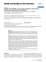
Using an optical trap, Smith et al. measured DNA
extension as a function of force on the DNA over the range
0–80 pN [23]. To do this, Smith et al. used k-DNA linked
at both ends to polystyrene beads, one of which was held
by a stationary micropipette and the other by an optical
trap, allowing the DNA to be stretched while monitoring
the force (Fig. 1A) using the trap potential. At low external
forces (< 10 pN), the DNA extension versus force curve
can be well fitted by the WLC model. As the DNA chain is
stretched towards it full contour length, the force abruptly
rises and reaches a plateau value of ~65 pN, at which point
the DNA abruptly overstretches to 170% of its B-form
contour length (Fig. 1B). The first-order-like transition into
the overstretched form of DNA (S-form) suggests that the
transition occurs cooperatively, unstacking bases into a flat
parallel ladder structure.
Beyond studying the physical properties of DNA,
researchers have extensively studied the interactions be-
tween optically trapped DNA and proteins. RNA poly-
merase (RNAP), for example, is a motor protein powered
by nucleotide triphosphate (NTP) hydrolysis during RNA
synthesis based on information read from DNA. Yin et al.
[24] measured the transcriptional velocity of E. coli RNAP
against an applied force on a DNA by directly monitoring
the displacement of a DNA molecule held by an optical
trap as it is transcribed by an immobilized RNAP (Fig.
2A). As RNAP actively transcribes the DNA, the bead is
pulled from the trap center, and a tension builds up on the
DNA until the force exerted by RNAP balances that ex-
erted by the optical trap. In this way, they showed that the
RNAP generates a considerable force (> 14 pN) during
transcription elongation.
Bustamante and coworkers investigated the effect of
assisting and opposing forces on the transcriptional pausing
and arrest of E. coli RNAP as shown in Fig. 2B[25, 26].
During transcription, E. coli RNAP is known temporarily to
stop or ‘‘pause’’ its transcription elongation or in some cases
undergo an irreversible structural change leading to a per-
manent halt or ‘‘arrest’’ of transcription. These pauses and
arrests are deviations from the main elongation pathway, and
play an important role in the regulation of gene expression. In
their experiments, a ternary complex including DNA tem-
plate, RNAP, and nascent RNA is stalled at a predetermined
position, followed by immobilization of RNAP onto a bead
surface which is optically trapped. Depending on the
geometry of the complex, the buffer flow stretching the DNA
can either assist or oppose transcription elongation
(Fig. 2B). Pauses of RNAP seen during the transcription in
assisting geometry are shown in Fig. 2C. Bustamante and
coworkers found that the force either opposing or assisting
the transcription elongation does not affect the transcrip-
tional velocity. This is consistent with the results of Yin et al.
who found that the transcriptional velocity is force-inde-
pendent until the force is high enough to deactivate the
protein, suggesting that mechanical translocation of RNAP
is not a rate-limiting step in transcription elongation. Nev-
ertheless, the force assisting the transcription elongation
apparently decreases the pause frequency and increases both
the mean transcription length and the fraction of pause-free
transcription compared to the case where the force opposes
transcription elongation, indicating that the entry into the
pause state is force-dependent. However, the exit from the
paused state is observed to be force-independent, suggesting
that the transition state between the entry into and exit from
the paused state is asymmetrically positioned in the reaction
Fig. 1 (A) Schematic of experimental setup used in [20]. (B) Force
versus extension for k-DNA in 150 mM NaCl, 10 mM Tris, 1 mM
EDTA, pH 8.0. Reprinted with permission from Science 271, 795
(1996). Copyright 1996 by the American Association for the
Advancement of Science
Nanoscale Res Lett (2007) 2:185–201 187
123
coordinate, with one state energetically favored. Similar
results have been observed with transcriptional arrests where
the assisting force reduces the incidence of arrest, although
the exit from the arrested state is rarely observed. These
experiments elucidate details of the reaction pathways of
prokaryotic transcription that are not available from con-
ventional bulk studies.
Multiple optical traps can be used to grab one or more
DNA molecules by their ends simultaneously. For exam-
ple, van den Brook et al. [27] investigated the dependence
of restriction enzyme activity on the tension exerted on
DNA optically trapped at both extremities as shown in
Fig. 3A. The tension on the DNA was controlled by
moving the position of one of the optical traps while
monitoring the force on the DNA with the other trap. Type
II restriction enzymes EcoRV and BamHI were used to
Fig. 3 (A) Schematic representation of experimental setup used in
Ref. [27]. (B) The reaction pathway for type II restriction enzymes.
The applied tension opposes DNA bending by the enzyme in the
induced-fit process. Reprinted with permission from Nucleic. Acids
Res. 32, 3040 (2005). Copyright 2005 by Oxford University Press.
(C) Schematic representation of experimental setup used in Ref. [28].
(D). Kinetic scheme for transcription by T7 RNAP. E denotes free
enzyme state; D, DNA template; ED
c
, DNA-bound closed complex;
ED
o
, DNA-bound open complex; E
init
D ÀN
m
, ternary complex
engaged in abortive RNA synthesis; E
elong
D–N
n
, ternary complex
engaged in elongation; PP
i
, pyrophosphate. Reprinted from J. Biol.
Chem. 279, 3239 (2004). Copyright 2004 by the American Society for
Biochemistry and Molecular Biology
Fig. 2 Schematic representations of experimental setup used in (A)
Ref. [24] and (B) Refs. [25, 26]. (C) The length between two beads
changes as RNAP transcribes DNA under a force that assists forward
transcription. Pauses during transcription are indicated by arrows.
Reprinted from Proc. Natl. Acad. Sci. USA 99, 11682 (2002).
Copyright 2002 National Academy of Sciences, USA
188 Nanoscale Res Lett (2007) 2:185–201
123
cleave the DNA at specific locations (‘‘GATATC’’ for
EcoRV and ‘‘GGATCC’’ for BamHI) which was registered
by a sudden drop in the tension. This study showed that the
cleavage rate for EcoRV decreases with DNA tension
whereas that for BamHI remains constant as long as the
tension is not so high as to overstretch the DNA. The
difference in the dependence of cleavage rate on the DNA
tension could be traced to dissimilarity between two en-
zymes in the ‘‘induced-fit’’ reaction with DNA, with the
tension-dependent enzyme significantly bending the DNA
upon binding. Their results were consistent with the crys-
tallographic images of the two enzymes bound to their
cognate sequences wherein EcoRV strongly bends the
DNA inside the binding pocket while BamHI does not
(Fig. 3B).
Using a dual optical trap setup, Skinner et al. [28]
investigated promoter binding, initiation, and elongation of
RNA by T7 RNAP. Bacteriophage T7 RNAP is a single
subunit enzyme fully capable of transcribing DNA into
RNA just as does the much more complicated eukaryotic
RNAP. In the experiment of Skinner et al., an optically
trapped DNA bearing a T7 promoter sequence was
maneuvered to interact with T7 RNAP immobilized to a
bead on a glass coverslip by applying a triangular wave-
form displacement on one of the traps, while monitoring
the coupled motion of the other bead (Fig. 3C). The
RNAP–DNA interaction was identified through changes in
the ‘‘stiffness’’ of the response of the second bead to
motion of the first. In this way, they measured the lifetime
of T7 RNAP bound to the promoter, from which they could
obtain the dissociation rate constant k
off
. In some DNA-
binding events that lasted much longer than others, a clear
movement of one of the beads toward the surface-bound
bead against the optical restoring force was observed. The
rate at which the distance between these two beads de-
creased corresponded to the transcriptional velocity k
pol
.
They could also directly measure the duration of the lag
between transcriptional initiation and elongation by mea-
suring the time between onsets of the DNA-binding and
unidirectional bead movement corresponding to the tran-
scriptional elongation. The stationary complex may repre-
sent a ternary complex engaged in abortive RNA synthesis
in which a short RNA chain of length 7–12 nt is repeatedly
released. The forward rate k
fow
at which the closed com-
plex transitioned to the elongation complex could be ob-
tained using the measurements of lag times (Fig. 3D).
Magnetic traps
Magnetic traps operate similarly to optical traps in that
they allow free maneuvering of a bead in solution. Just as a
particle is trapped in a potential well created by the laser
intensity profile in an optical trap, the force generated by an
electromagnetic field gradient traps a magnetic particle.
Typically, one end of the DNA molecule is fixed on a
surface while the other end, to which the magnetic bead is
attached, is held by the magnetic trap in solution (Fig. 4).
The force on the DNA, which can be varied by changing
the distance between the magnet and the bead, typically
ranges from tens of fN to ~100 pN. The extension of the
DNA in the vertical direction (l) can be measured by
analyzing the bead image using a diffraction ring whose
diameter increases with the distance of the bead from the
focal plane. The magnetic force on the DNA can be
computed using the equipartition theorem in which the
force is expressed as F
mag
¼ k
B
Tl=hdx
2
i, where dx is the
transverse Brownian fluctuation of the bead [29].
In early experiments with magnetic traps, Smith et al.
[30] studied the elasticity of single DNA molecules by
measuring the DNA extension as a function of external
force. In their setup, one end of the DNA was chemically
attached to a surface and the other end to a magnetic bead
held by the magnetic trap. The DNA was forced to stretch
upward by a hydrodynamic flow and was simultaneously
pulled to the right by the magnetic trap, creating an angle h
relative to the horizontal axis. The tension on the DNA was
calculated from the measured values of F
mag
and h. They
found that the extension versus force curve for a double
stranded DNA molecule deviates from the prediction of the
freely jointed chain (FJC) model, which assumes that the
Kuhn segments are uncorrelated in the absence of external
forces. A more precise description of the DNA elasticity
was provided by taking into account the continuous rigidity
of the polymer chain through the inextensible WLC model,
although this model fails to describe the DNA under ten-
sions greater than 10 pN. Marko later proposed an exten-
sible WLC model that also includes twisting elasticity as a
Fig. 4 Schematic representation of the force measurement. The mag-
netic force applied to the bead stretches the DNA vertically. The
transverse Brownian fluctuation of the bead dx is used to calculate the
force using the equipartition theorem in which the force is expressed
as F
mag
¼ k
B
Tl=hdx
2
i
Nanoscale Res Lett (2007) 2:185–201 189
123
model for DNA that can be applied to DNA under high
tensions [31].
Bensimon and coworkers have pioneered the study of
DNA–protein interactions using magnetic traps. In one of
their experiments, Maier et al. [32] measured the real-time
replication rate of a single DNA polymerase (DNAP) on a
single-stranded DNA (ssDNA) stretched by a magnetic trap
as shown in Fig. 5A. Similarly to RNAP, DNAP reads the
base sequence information from a single-stranded template
and synthesizes the complimentary strand. The differences
between DNAP and RNAP include (1) catalyzing of
addition of a new deoxyribonucleotide triphosphate
(dNTP) to the growing chain of DNA for DNAP while
RNAP catalyzes the addition of NTP to the growing chain
of RNA; and (2) DNAP requires a primer (a short piece of
ssDNA annealed to the template strand) to initiate the
synthesis while RNAP does not. Maier et al. tracked in
real-time the progress of replication by measuring the
change in the elastic response to an external force that
occurs as ssDNA is converted to double-stranded DNA
(dsDNA) (Fig. 5B). At low forces (< 5 pN), the elasticity
of dsDNA can be well described by the WLC model as
mentioned in the previous section, while that of ssDNA
exhibits a complex behavior due to the secondary structure
which varies with ionic strength and base composition. In
the low force regime (< 5 pN), a higher force is required to
stretch ssDNA than to stretch dsDNA to the same extent,
while a crossover occurs at a force of ~5 pN. The extension
versus force behavior of a partially replicated DNA is
intermediate between ssDNA and dsDNA, which can be
well described by the superposition of the elastic behavior
of ssDNA and dsDNA. In this way, the DNA extension is
converted into the number of dNTP incorporated into the
growing DNA chain. Two different DNAPs were used in
their experiments, both of which exhibit frequent pauses
during the synthesis and show a decrease in the replication
rate when the force exceeds 4 pN. The decrease in the
replication rate is attributed to the work that DNAP has to
perform against the external load to contract the template
in order to fit it into the dsDNA structure during the
polymerization rate-limiting step. We note that a similar
experiment has been carried out using an optically trapped
DNA molecule [33].
Bensimon and coworkers [34] followed in real time the
interaction between a type II DNA topoisomerase (topo)
and dsDNA that had been stretched and supercoiled by a
magnetic trap. Type II topo is an ATP-dependent protein
that relaxes positive supercoiling by removing two super-
coils per cycle to ensure proper segregation of DNA into
daughter chromosomes. Supercoiling of DNA can be
introduced simply by rotating the magnet above a surface-
anchored un-nicked DNA molecule. The torque on the
DNA builds up until it reaches the critical value at which
the DNA buckles, forming a plectoneme (Fig. 6A). The
DNA contracts in length by d(d = 45 nm per turn at a
constant force of F
mag
= 0.7 pN) as more positive super-
coils are generated by the continued twisting of the DNA
(Fig. 6B). As topo II is added to the system at low ATP
concentration, the stepwise DNA extension by 2d can be
observed each cycle in which the protein removes two
supercoils (Fig. 6C).
Fig. 5 (A) Schematic representation of experimental setup used in
Ref. [32]. The magnets pull on the bead with a force F
mag
\100 pN.
A primer is hybridized to the ssDNA for DNAP to initiate replication.
As DNAP progresses, the molecule’s extension increases due to the
difference in the elastic behavior between ssDNA and dsDNA. The
stretching force is increased to 50 pN to separate the newly
synthesized strand from the template strand by destabilizing the
DNA. (B) Comparison of the elasticity of a charomid and pXD II
ssDNA and the WLC model curve for dsDNA. The difference in
G + C content in ssDNA molecules influences the stability of
secondary structure at low forces. (C) The force versus extenstion
curve of a partially replicated DNA (squares) is intermediate between
ssDNA (circles) and dsDNA (diamonds). The full line
l
p
ðFÞ¼pl
ds
þð1 À pÞl
ss
is the superposition of elastic behavior of
ssDNA and dsDNA at a percentage of replication of p = 0.7. All
figures reprinted from Proc. Natl. Acad. Sci. USA 97, 12002 (2000).
Copyright 2006 by National Academy of Sciences, USA
190 Nanoscale Res Lett (2007) 2:185–201
123
Electrostretching
Stretching and immobilization of DNA in solution can also
be performed by applying AC fields using microfabricated
electrodes. Spatially non-uniform AC fields lead to
molecular movement induced by polarization, which is
known as dielectrophoresis (DEP). Depending on their
polarizability relative to the solvent in which they are
immersed, molecules tend to migrate towards either the
highest field strength (positive dielectrophoresis) or the
lowest (negative dielectrophoresis) [35]. Long polymers
not only migrate but also align or stretch in the AC field,
due to the tendency of the segments of polymer to align in
the field, since unaligned segments experience an electric-
field-induced torque acting on the induced dipoles [36];
i.e., a dielectric torque. Orientation due to this dielectric
torque is sometimes also called ‘‘dielectrophoresis,’’ but
here, to avoid confusion, we will restrict the term ‘‘di-
electrophoresis’’ to migration in an AC field due to spatial
gradients in the field. In addition to dielectric forces, such
experiments can also induce electrothermal force acting on
the fluid, whereby each electrode induces a circulatory
fluidic motion across the electrodes [35]. This field-induced
flow in turn contributes to DNA stretching [37]. In order to
overcome the random thermal forces experienced by the
DNA in solution, the electric field required for stretching is
typically very high (around 10
6
V/m), which, however, can
easily be generated using microfabricated electrodes, since
gaps between electrodes are then very small. Often in such
experiments, one end of the DNA molecule is first immo-
bilized on one electrode followed by stretching the other
end by the AC field.
Washizu and Kurosawa [15] were the first to demon-
strate DNA immobilization and stretching using an AC
electric field in deionized water (conductivity 2 lS/cm).
They used microfabricated aluminum electrodes deposited
and patterned on glass to manipulate k-DNA molecules.
The DNA molecules were covalently attached to the alu-
minum electrodes by an electrochemical process [38].
After attachment, the DNA molecules were stretched using
a 1 MHz field. A floating electrode configuration was used
to minimize the electrothermal force generated along the
electrode edge, thus enabling the DNA molecule to attach
to the electrode.
Namasivayam et al. [39] demonstrated DNA stretching
in a microfluidic channel using non-uniform electric fields.
Tris–HCl medium mixed with 3.75 wt% linear polyacryl-
amide was used to enhance DNA stretching [40]. The DNA
molecules were found to stretch partially at around 1 KHz
and also to stretch more fully at around 1 MHz. The
existence of significant stretching at both these frequency
ranges has been attributed to two distinct time constants
governing relaxation of the counterion cloud present
around the DNA molecule, one of these constants gov-
erning the tight ‘‘Stern’’ layer and the other the diffuse
layer [41]. However, in the presence of an entangled
polymer solution, additional mechanisms of stretching may
be possible, due to ‘‘reptation’’ of the DNA through the
polymer matrix [40]. Namasivayam et al. immobilized
DNA molecules onto gold electrodes at 1 KHz using a
thiol group bound to the 3¢ end of the DNA. After
attachment, the DNA was stretched and immobilized at the
other end across a 20 lm electrode gap using 1 MHz AC
field as shown in Fig. 7.
In subsequent work, Sung et al. [42] used a similar setup
to study the efficiency of DNA stretching for different
surface conditions and electrode designs in deionized water
(pH 8.0, conductivity 2 lS/cm) mixed with 4 wt% poly-
acrylamide solution. They applied 1 KHz AC fields to at-
tract the DNA molecules to the electrode’s edge
(apparently due to positive DEP) to enable DNA–thiol
attachment to the gold electrode. After immobilization the
DNA molecules were stretched and anchored at the other
end using a 1 MHz field. The stretching that occurred at
1 MHz might have arisen either by a negative DEP or a
flow that induced stretching.
Fig. 6 (A) Schematic representation of the buckling instability of
dsDNA undergoing topo II- mediated clamping in the absence of
ATP. Topo II can stabilize the DNA supercoil by binding to the
crossover between two DNA segments in the absence of ATP. (B)
The relaxation of supercoils in the presence of topo II and ATP. Two
supercoils are removed in each enzymatic cycle, resulting in an
increase in the DNA extension by 2d.(C) Individual steps of increase
in the DNA extension are observed. All figures reprinted with
permission from Nature 404, 901 (2000). Copyright 2000 by Nature
Publishing Group
Nanoscale Res Lett (2007) 2:185–201 191
123
From these experiments, Sung et al. deduced that more
efficient DNA stretching can be carried out with hydro-
phobic surfaces and thin electrodes than with those used in
the experiments of Namasivayam et al. The physical phe-
nomena behind DNA stretching for different frequencies,
pH and conductivity of buffer, electric field strength and
distribution, and the enhancement of stretching by poly-
acrylamide, are still not clear. Currently there are no
equations that can describe the behavior of DNA stretching
under different conditions [43]. The different forces and
their influence on DNA stretching have yet to be fully
understood.
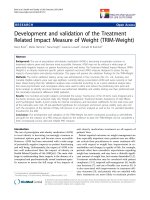
Germishuizen et al. [44] conducted DNA stretching
experiments (without added polymer) with a parallel
electrode pair to study different forces that contribute to
DNA stretching. DNA molecules were immobilized at
one end to a gold electrode using a multi-step procedure
involving biotinylation, thiolation and hybridization. The
stretching of DNA molecules of different contour lengths
was studied at various frequencies in deionized water
(conductivity 1 lS/cm). They found that DNA stretching
at first increases, and then decreases with increasing
frequency as shown in Fig. 8. The maximum elongation
was observed around 200–300 KHz for all different DNA
fragments while no stretching was observed at frequen-
cies below 100 KHz or above 1.1 MHz. The decreased
stretch lengths at higher frequencies could be due to an
inability of the DNA segment dipoles to respond at the
highest frequencies. The same study showed that the
normalized stretch was independent of the contour length
and the position of the segment of interest, i.e., the
distance from the electrode. From the above results and
experiments conducted with an electric-field-induced
fluid flow at different frequencies, the authors concluded
that both the field-induced segment orientation due to
dielectric torque and the induced flow contributed to the
DNA stretching, whereas the dielectrophoretic force
produced by the field gradient had little influence. Fur-
ther experiments conducted with varying electrode gaps
showed that DNA molecules can only be elongated to
half the electrode gap if the DNA contour length is
longer than the electrode gap.
Walti et al. [37] studied DNA stretching by recording
images both parallel and perpendicular to the plane of
the electrode, and concluded that the major contribution
to stretching is from the AC-field-induced dielectric
torque while the directionality of stretching is provided
by the electric-field-induced flow. They argued that the
dielectric torque tends to align molecular segments but
cannot on its own produce stretching, since the segments
will align equally both parallel and anti-parallel to the
field, unless a bias is introduced. The field-induced flow
is one source of a bias. To stretch the DNA, the induced
flow has to be directed from the electrode edge towards
the gap. Also, DNA molecules with contour length
greater than half the electrode gap cannot be stretched
beyond the center of the gap because the electric-field-
induced fluid flow from both electrodes changes direction
midway between the gaps. DNA molecules cannot stretch
in a direction opposite to the induced flow. However, for
high fields, Cohen [36] pointed out that the dielectric
torque can produce full stretching, since there is a
bending energy associated with each ‘‘kink’’ where the
DNA alignment changes direction, and this bending en-
ergy is only eliminated when the kinks disappear, and
the molecule is then fully stretched. Thus, there is not
necessarily a need for a ‘‘bias’’ to produce full stretching
of DNA by dielectric torque.
DNA molecules can also be immobilized to gold elec-
trodes by preparing the DNA solution in a weak acidic
buffer (pH 5.5–6.6). The DNA becomes ‘‘sticky’’ at the
Fig. 7 Single k-DNA molecule immobilized and stretched across
20 lm electrode gap using AC field (1 MHz, 3 Â 10
5
V/m), in a
linear polyacrylamide solution. Reprinted with permission from Anal
Chem. Copyright 2002 by American Chemical Society
Fig. 8 Stretch length of elongated DNA as a function of frequency at
an electric field of 0.5 MV/m across a 40 lm gap; 48 kb (closed
squares), 35 kb (open squares), 25 kb (closed circles), and 15 kb
(open circles). Reprinted with permission from J. Appl. Phys. 97,
014702 (2005). Copyright 2005 by American Institute of Physics
192 Nanoscale Res Lett (2007) 2:185–201
123
ends at low pH conditions due to protonation of bases
leading to the exposure of hydrophobic core as will be
discussed more in detail in section ‘‘Stretching by a
moving interface.’’ Using these DNA molecules, the
immobilization and stretching can be performed in a single
step without any chemical modifications to either the
electrode or the DNA. Dukkipati et al. [45] have demon-
strated DNA stretching and immobilization in microfluidic
channels in acidic condition (pH 5.8) and non-uniform
electric fields. When the electric field is applied across the
electrode gap below 8 V, DNA molecules are carried by
the electrothermal fluid flow and attach to the gold elec-
trode as shown in Fig. 9. At higher than 8 V, the induced
fluid flow reverses direction from the electrode edge to-
ward the gap for both electrodes) such that DNA molecules
stretch from both sharp- and straight-edged electrodes as
shown in Fig. 9C.
Electrostretching of DNA molecules has been used to
aid the study of the motion of DNA-interacting proteins
along the DNA molecule. Kabata et al. [46] have directly
observed fluorescently labeled EcoRI proteins sliding un-
der convective flow along electrostretched DNA molecules
held between electrodes. In these experiments, sliding
along the DNA was distinguished from simple convection
in the flow by a change in direction of the motion of the
stained proteins when they encountered the DNA mole-
cules. One possible future application of stretching DNA
molecules across electrode gaps is a fabrication of a net-
work of DNA-templated carbon nanotube (CNT) transis-
tors to realize fully functional digital blocks such as
inverters and adders [47]. In the construction of these CNT
transistors, electrostretching may be of advantage in that it
allows placement of stretched DNA molecules at precise
locations across electrodes [45], as opposed to DNA
combing, in which DNA placement is random. We will
discuss combing in more detail in section ‘‘Stretching by a
moving interface’’.
Flow stretching
Stretching by hydrodynamic drag
As mentioned in the section ‘‘Introduction,’’ stretching and
immobilization of DNA using flow occurs either by
hydrodynamic drag or the action of a moving meniscus. In
this section, we discuss methods that use hydrodynamic
drag. We have already described a couple of experiments
that used a hydrodynamic buffer flow to stretch the free end
of a DNA molecule anchored at the other end by an optical
or a magnetic trap. In this section, we discuss experiments
in which the DNA is attached to a surface at one end by an
avidin–biotin linkage and is free in solution at the other end
(Fig. 10A). Avidin is a tetrameric protein each subunit of
which provides a strong binding site for a biotin molecule.
A monolayer of avidin can deposited directly onto an acid-
cleaned glass surface [3], or onto either a monolayer of
biotin-labeled BSA [48] or a biotin-poly(ethylene glycol)
brush, which is known to reject non-specific binding of
proteins [49, 50]. The biotin labeling of the DNA is gen-
erally carried out by annealing a biotin-modified oligonu-
cleotide to the DNA. As discussed earlier, the force on the
DNA can be obtained from the transverse Brownian motion
of the free end of the DNA using the equipartition theorem.
van Oijen et al. [14] observed the digestion by k exo-
nuclease of dsDNA into ssDNA at the single-molecule
level. k exonuclease degrades each strand of duplex DNA
in the 5¢ to 3¢ direction by means of hydrolysis of phos-
phodiester bonds in a highly processive manner. In each
enzymatic cycle, k exonuclease catalyzes the hydrolysis of
a phosphodiester bond, translocates along the DNA, and
melts the 5¢ terminal base from neighboring bases. Three
oligos were annealed to the DNA to ensure that modifi-
cations in extremities to provide binding sites for avidin
and microsphere occur at one strand only, leaving the other
5¢ terminus exposed to initiate the digestion. As in the
Fig. 9 DNA stretching for different voltages at 100 KHz in a 100 lm
wide and 75 lm deep Si microchannel. (A) DNA stretching starts at
the tip of pointed electrode at 8 V. (B) Greater numbers of stretched
DNA molecules covering a greater area are observed near the tip of
the pointed electrode at 12 V. (C) DNA molecules stretched at both
the straight edge and pointed electrodes at 16 V. Reprinted with
permission from Appl. Phys. Lett. 90, 083901 (2007). Copyright 2007
by American Institute of Physics
Nanoscale Res Lett (2007) 2:185–201 193
123
experiments of Maier et al. presented in the previous sec-
tion, the transition from dsDNA to ssDNA is detected by
monitoring the elastic response to low stretching forces
(<6 pN). van Oijen et al. observed the decrease in the DNA
length as k exonuclease specifically degrades one strand of
the dsDNA (Fig. 10B). The digestion rate exhibits large
fluctuations depending on the position along the DNA
template, suggesting that a sequence-dependent melting of
the base pair (bp) is the rate-limiting step in the enzymatic
cycle (Fig. 10C).
Blainey et al. [51] observed the 1D Brownian motion of
human oxoguanine DNA glycosylase 1 (hOgg1) along
similarly flow-stretched DNA. DNA glycosylases initiate
DNA repair by catalyzing excision of damaged bases and
hOgg1 in particular removes highly mutagenic base 8-
oxoguanine from the human genome. The protein has to
locate these damaged bases amidst the vast number of
native bases and the question of how these DNA-binding
proteins locate their target sequence has long remained
unanswered. It has been proposed that proteins reach their
target sequence in part by a facilitated diffusion along the
contour of the DNA [52, 53]. The mechanisms of facili-
tation could include 1D ‘‘sliding’’ of proteins along the
DNA contour and short range ‘‘hopping’’ or long range
‘‘jumping’’ of proteins through 3D space from one site to
another on the DNA. The DNA was attached to a surface at
one end by avidin–biotin linkage while the other end was
free in solution. The protein was fluorescently labeled with
Cy3B at the C-terminal engineered cysteine. When these
proteins were introduced into a flow cell by a strong shear
flow which also stretched the DNA on the surface, Blainey
et al. observed the 1D movement of single proteins along
the DNA (Fig. 11A). These proteins exhibited a typical 1D
Brownian motion in which the net displacements were
symmetric around zero. The 1D diffusion coefficients (D
1
)
were obtained by plotting the mean-square displacements
(MSD) as a function of time at various salt concentrations.
Varying the salt concentration is expected to influence the
protein diffusion by changing the non-specific binding
affinity if the search mainly occurs through 3D space.
However, the D
1
values obtained in their experiments
exhibited no dependence on salt concentrations despite the
apparent decrease in binding lifetimes (Fig. 11B), sug-
gesting that during the sliding the protein maintains reg-
istry with the DNA, and does not hop on and off, since the
rate of re-binding to the DNA should be affected by
salinity. These results demonstrate how single-molecule
techniques can be used to characterize directly molecular
properties that could not have been measured with con-
ventional bulk studies.
Our group and others have also stretched DNA molecules
in a flow generated by drying a droplet deposited onto a
positively charged surface such as one treated with
Fig. 10 (A) Schematic representation of the experimental setup in
which biotinylated DNA is immobilized at one end to an avidin-
coated surface while the free end is stretched by buffer flow. (B) Two
digestion trajectories showing complete conversion of dsDNA into
ssDNA by k exonuclease. Two black traces correspond to beads
tethered to ssDNA (top) and dsDNA (bottom). (C) Time derivatives
of the two trajectories in (B) as a function of template position.
Figures in (B) and (C) are reprinted from Science 301, 1235 (2003).
Copyright 2003 by the American Association for the Advancement of
Science
194 Nanoscale Res Lett (2007) 2:185–201
123
aminopropyltriethoxy silane (APTES) [54, 55]. When the
contact line is pinned to this surface, a radial flow is created to
replenish fluid that is evaporated from the periphery of the
droplet [56]. This flow both transports DNA molecules to-
wards the periphery and stretches them. Since the DNA is
negatively charged along the backbone, it sticks to the pos-
itively charged APTES surface via electrostatic interactions,
or, more precisely, it adheres to the surface due to the entropy
gained by releasing counterions. Jing et al. [54] and Chopra
et al. [55] have reported the deposition of k DNA molecules
onto an APTES-treated surface via a drying droplet flow.
Brownian dynamics simulations using a bead-spring repre-
sentation of the DNA molecule predict 22% stretching for
DNA molecules adsorbed near the edge of the droplet (i.e., at
radial positions greater than 90% of the droplet radius) for
droplets dried under relatively ‘‘fast’’ evaporation condi-
tions (i.e., low humidity), which agreed with the experi-
mental findings (Fig. 12). This stretch is much poorer than in
meniscus-force-driven stretching. From the simulations, one
can infer that this rather poor stretching is due to the down-
ward convective flow created inside the drying droplet which
tends to push DNA molecules onto the surface before they
get chance to fully unravel.
Although these DNA molecules are not in general fully
stretched, they are a good template for an optical mapping
application. DNA molecules that are stretched and firmly
immobilized onto a surface can be cleaved by type II
restriction enzymes at one or more positions along the
backbone. As mentioned in the previous section, type II
restriction enzymes cleave both strands of the DNA by
recognizing a specific sequence on the DNA and catalyzing
the hydrolysis of phosphodiester bonds. In order to opti-
cally locate the positions of cleavage, it is desirable that the
cleaved fragments be retained in their original locations.
Jing et al. [54] have demonstrated the enzymatic cleavage
of k-DNA molecules that were stretched and immobilized
onto an APTES-treated surface by drying droplet flow. The
DNA fragments were well preserved on the surface as
shown in Fig. 13.
Stretching by a moving interface
Bensimon and coworkers developed a simple, but very
clever, method to stretch and align large number of DNA
molecules onto a hydrophobic substrate by the action of a
receding water meniscus [16, 17]. This so called ‘‘molec-
ular combing’’ method is carried out as follows: (1) the
DNA is dissolved in a buffer solution at pH 5–7, slightly
below the physiological pH in order to slightly denature
DNA at its the ends; (2) a hydrophobic substrate is dipped
into a the DNA-containing solution; and (3) the substrate is
slowly pulled out of the solution, leaving highly aligned
DNA molecules firmly attached to the substrate (Fig. 14A).
In this remarkably simple method, the stretching and
anchoring of the DNA is believed to come about in the
following way. First, a free end of the DNA sticks to the
hydrophobic substrate, presumably due to its affinity to the
exposed hydrophobic bases at the end of the DNA; then the
DNA molecule is stretched out by the force exerted on the
rest of the DNA by the receding meniscus; and finally the
other end also sticks to the substrate as it dries. The process
results in a high-throughput alignment of DNA molecules.
However, the force exerted on the DNA by the receding
water meniscus is strong enough to ‘‘overstretch’’ the
dsDNA by as much as 60% beyond the length of its
physiological B-form helix, and the DNA molecules often
stick to the substrate at multiple points along the backbone,
limiting their ability to interact with proteins. Our group
has recently demonstrated that the number of anchor points
along the DNA backbone can be controlled by varying the
pH [57]. At physiological pH the DNA bases are not lo-
cally melted and the adsorption occurs primarily at its ends,
reducing the chances for attachment at other points along
the DNA backbone. This also leads to a higher, more
uniform stretch at this pH, apparently because avoidance of
these interior attachment points removes ‘‘anchor points’’
that are present at lower pH and inhibit transmission of the
meniscus force to the entire DNA molecule (Fig. 14B).
The stretching can be further enhanced by using surfaces
Fig. 11 (A) Image of single hOgg1 protein molecules bound to flow-
stretched k-DNA. Scale bar = 1.0 lm. (B) Mean binding lifetime
(open symbols) and 1D diffusion coefficient (closed symbols)as
functions of salt concentration. All figures reprinted from Proc. Natl.
Acad. Sci. USA 103, 5752 (2006). Copyright 2006 by National
Academy of Sciences, USA
Nanoscale Res Lett (2007) 2:185–201 195
123
with low hydrophobicity which have reduced non-specific
interactions with the DNA.
Gueroui et al. [4] have demonstrated that the overstret-
ching of DNA can be suppressed by reducing the surface
tension at the air/solution interface using a monolayer of
fatty alcohol. In this way, they have deposited non-over-
stretched DNA molecules onto a hydrophobic substrate
which served as a template for T7 transcription system.
Gueroui et al. also visualized transcription on single
combed T7 DNA molecules by using fluorescently labeled
uridine triphosphate (UTP). This fluorescent monomer is
incorporated into the growing RNA chain, generating a
fluorescence signal as T7 RNAP transcribes the combed
DNA to synthesize RNA. These RNA transcripts are
visualized as bright dots aligned linearly on top of combed
DNA (Fig. 14C). The RNAP–RNA transcript complex
translocates along the DNA until it encounters an anchor
point at which the DNA is attached to the surface. At this
point, the protein complex stops and accumulates on the
DNA as suggested by multiple fluorescent dots when
multiple transcription initiation is allowed. When RNase
T1, which degrades RNA in its coiled form, is introduced
in the system, the bright dots are eliminated, suggesting
that the RNA is not hybridized to the DNA.
Combed DNA molecules can also be used for ‘‘optical
mapping,’’ which is a method devised by Jing et al. [54]of
quickly locating endonuclease restriction sites along DNA
molecules at optical resolution, and is useful for providing
a ‘‘scaffold’’ for assembling DNA ‘‘shotgun’’ sequence
data on small fragments (~1,000 bps) into a continuous
sequence for a long DNA molecule. Although DNA mol-
ecules are frequently overstretched during combing, we
find that the stretched lengths have a wide distribution
when combed at low pH conditions as compared to the
more uniform length distribution obtained for combing at
physiological pH condition. As mentioned above, we be-
lieve that this is because combing at low pH conditions
results in multiple anchor points along the backbone that
prevent the meniscus force from being fully transmitted to
the DNA [57]. However, the possible contribution of DNA
breakage to the distribution of DNA stretch lengths is
difficult to rule out. Since a large number of DNA mole-
cules are stretched and deposited in a single run, we expect
in each run to find a number of non-overstretched mole-
cules capable of interacting with a restriction enzyme. To
carry out the optical mapping, we simply comb YOYO-1
stained DNA molecules onto a hydrophobically treated
cover glass, deposit a drop of EcoRI solution on top of this,
incubate the solution in the dark for 20 min, and then
illuminate and image the DNA quickly, to avoid photoc-
leavage. EcoRI recognizes and cleaves DNA at the
Fig. 12 DNA images at the
edge of a droplet (radial
position > 90%) at (A) a high
evaporation rate (3 min drying
time) and (B) a low evaporation
rate (6 min drying time). (C),
(D) Simulated DNA images
under conditions identical to
those in the experiments in (A)
and (B), respectively. Scale
bars = 20 lm. All figures
reprinted with permission from
J. Rheol. 47, 1111 (2003).
Copyright 2003 by the Society
of Rheology
Fig. 13 Image of k-DNA molecules stretched and immobilized on
the APTES surface, digested with AvaI restriction enzyme. Reprinted
from Proc. Natl. Acad. Sci. USA 95, 8046 (1998). Copyright 1998 by
National Academy of Sciences, USA
196 Nanoscale Res Lett (2007) 2:185–201
123
six-base-pair-long cognate sequence ‘‘GAATTC’’ which
occurs at five locations on k-DNA, yielding six fragments
of different lengths. Although the DNA is bound to the
surface by combing, nevertheless, all five specific locations
were recognized by EcoRI as shown in Fig. 15. The
observed cleavage sites are in good agreement with the
predicted cleavage sites, which confirms that DNA mole-
cules are cleaved by EcoRI rather than by photocleavage.
EcoRI-conjugated nanoparticles can also be incubated with
fluorescently labeled lambda phage DNA molecules and
then stretched onto a hydrophobic surface by combing.
Several examples of EcoRI-conjugated nanoparticles at-
tached to DNA molecules at the expected restriction sites
(Mg
2+
was not added in order to prevent DNA cleavage),
are shown to within optical resolution (Fig. 15F). We note
that similar cleavage of combed DNA by EcoRI has been
observed by Yokota et al. [58].
Other methods of stretching and immobilization of DNA
molecules using moving interface include spin-coating and
air-blowing [57]. Both methods rely on fast motion of an
air–solvent interface, generated by the centrifugal force
exerted on a droplet of DNA solution deposited on the
rotating disk for spin-coating and by blowing an air jet at
the side of a droplet of DNA solution placed on a hydro-
phobic substrate for air-blowing. The fluid flow in these
methods however, is difficult to characterize and deforms
the droplet of DNA solution randomly, complicating the
stretching mechanism.
DNA stretching and immobilization
in a micro/nano-channel
Instruments and techniques used for DNA stretching and
immobilization such as optical and magnetic traps, as well
as electric fields, results in small numbers of immobilized
DNA molecules. In applications such as haplotyping for
personalized medicine and pathogen detection by com-
parative genomics, analyses need to be performed on large
number of stretched DNA molecules to eliminate the false
positives that may arise when a fluorescent marker is at-
tached to a non-specific sequence on the DNA molecule
[59, 60]. For these purposes, there is a growing need for
technology that will allow high throughput and low cost
analysis of stretched and immobilized DNA molecules. A
new technique that we call ‘‘protein-assisted DNA immo-
bilization’’ (PADI) generates hundreds or thousands of
stretched and immobilized DNA molecules in a micro-
channel [19]. The PADI technique is based on the general
phenomenon of protein adsorption to hydrophobic sur-
faces, combined with the fact that specialized proteins that
interact with DNA (such as restriction enzymes, RNA
polymerases, etc.) also bind to DNA molecules. In the
PADI method, DNA-interacting proteins are allowed to
bind to the DNA molecule in bulk. When this DNA–pro-
tein complex is introduced into a microchannel, the DNA is
stretched by hydrodynamic flow followed by DNA
immobilization at the surfaces. The DNA is attached to the
hydrophobic microchannel surfaces through protein
adsorption, resulting in immobilization of DNA molecules
inside the microchannel. Shown in Fig. 16A is an image of
large number of k-DNA molecules stretched and immobi-
lized in a 100 lm wide and 1lm deep microchannel using
RNAP as the DNA-interacting protein.
Fig. 14 (A) k-DNA molecules combed onto a poly(styrene)-coated
surface at pH 5.5. (B) The number of anchor points as a function of
stretch ratio (x/L, where x is the stretched length and L is the DNA
contour length) for T7 DNA molecules stretched at pH 8.0 on a
poly(methylmethacrylate)-coated surface, measured by a ‘‘photoc-
leavage assay.’’ Each pair of images shows a T7 DNA molecule
before (left) and after (right) the photocleavage. DNA molecules snap
back to the anchor points when they are photocleaved by exposure to
illumination. Scale bars = 2.5lm. The error bar displayed is the
standard error of the mean. Reprinted with permission from Langmuir
23, 755 (2007). Copyright 2007 by American Chemical Society. (C)
Fluorescently labeled RNA transcripts (red) formed along YOYO-
stained T7 DNA (green). Scale bar = 2.5 lm
Nanoscale Res Lett (2007) 2:185–201 197
123
The PADI technique offers several advantages over
some other methods: (1) overstretching of DNA molecules
is avoided; (2) the degree of attachment of DNA to the
substrate can be controlled by changing the protein con-
centration without changing the substrate material; (3) the
number of DNA molecules immobilized onto the substrate
is time and concentration dependent and can be controlled
simply by varying the pumping time as well as the con-
centration; (4) the stretching and immobilization is
achieved at physiological pH; (5) inexpensive microfabri-
cated devices are used; and (6) it only requires a couple of
microlitters of sample. The ability of the PADI technique
to produce different degrees of DNA attachment is dem-
onstrated in Fig. 16B and C. At high-protein concentration,
the DNA is firmly attached to the surface (Fig. 16B), while
lowering the protein concentration leads to fewer proteins
bound to DNA, resulting in a looser attachment of DNA to
the surface (Fig. 16C).
A number of DNA–protein interactions can be
performed on DNA molecules immobilized by PADI
including optical mapping and transcription. We have
demonstrated optical mapping of DNA molecules by first
immobilizing DNA by PADI in the presence of RNAP, and
then introducing type II restriction enzyme SmaI that
cleaves DNA at ‘‘CCCGGG’’ sequence. The cleaved
fragments are well preserved on the channel surface as
shown in Fig. 17A. We have also demonstrated transcrip-
tion of DNA molecules immobilized by PADI, similar to
the experiments discussed in section ‘‘Stretching by a
moving interface’’. We have stretched and immobilized T7
DNA molecules in the presence of T7 RNAP followed by
introduction of transcription buffer containing NTPs and
fresh RNAP. As shown in Fig. 17B, the transcripts are
detected when fluorescently labeled UTPs are incorporated
into the growing RNA chain, similar to those seen in the
experiments of Gueroui et al. [4], discussed above.
Austin and coworkers [61] investigated the statics and
dynamics of DNA molecules confined in varying size of
nanochannels of various widths. The elongation of a con-
fined polymer in the ‘‘de Gennes regime,’’ in which the
channel width D is much larger than the persistence length
of the DNA (D ) p), is purely due to excluded volume
interactions between segments of freely coiled polymer,
and is predicted to scale with D as x ffi L
dp
D
2
ÀÁ
1=3
, where d is
Fig. 15 (A)–(E) k-DNA
cleaved by EcoRI at specific
locations. (F) EcoRI-conjugated
fluorescent nanoparticles (red)
attached to a single k-DNA
molecule. The blue diamonds
are the expected restriction
sites, while red squares indicate
actual digestion or binding sites
198 Nanoscale Res Lett (2007) 2:185–201
123
the DNA diameter and L is contour length of the DNA. The
extension of a confined polymer in the Odijk regime (D (
p) is dominated by the interplay of confinement and
intrinsic DNA elasticity. The interactions of the polymer
with the channel walls extend the molecule since coiling
tightly enough to fit into the channel is made energetically
unfavorable. In this regime, the extension scales with D as
x @ L½1 À0:361ðD=pÞ
2=3
. The physics underlying the
behavior of the confined polymer is not well understood at
the crossover between the de Gennes and Odijk regimes.
Since the channel dimension of a typical nanodevice lies
near the crossover between the de Gennes and Odijk re-
gimes (D ~ p, where p ~ 50 nm), it is therefore critical to
understand the crossover behavior between two regimes.
Austin and coworkers obtained the DNA extension as a
function of the channel dimension by collecting the fluo-
rescence intensity transverse to the channel axis
(Fig. 18A). The deviation from the de Gennes power-law
seen for the DNA in the thinnest 30 nm wide channel
indicates that this channel width corresponds to the Odijk
regime. By matching the expression for the DNA extension
in the Odijk regime to the power-law fit, the crossover
scale of D
critical
~ 2 p is obtained.
Overview and final observations
We have reviewed different methods of stretching and
immobilizing DNA molecules for studying single-mole-
cule DNA–protein interactions. Single-molecule experi-
ments overcome the problem of ensemble-averaging of
molecular properties intrinsic to conventional bulk
experiments by directly interrogating each molecule one
at a time. Although advantageous for many purposes,
single-molecule experiments also suffer the drawback
that many repetitions of often-difficult and tedious
experiments are required in order to obtain sufficient
statistics to provide meaningful quantitative results and to
determine the range of behavior possible. It is therefore
critical to develop robust methods of DNA stretching and
immobilization that offer both high sensitivity and high-
throughput detection of DNA–protein interactions. Opti-
cal and magnetic traps allow the most accurate mea-
surements of changes in physical properties of DNA in
Fig. 16 (A) k-DNA (5.5 pM) stretched and immobilized in the
presence of T7 RNAP (10 nM). T7 DNA molecules are immobilized
at (B) 5 nM and (C) 0.5 nM T7 RNAP concentration, followed by
DNA photo-cleavage by exposure to illumination, revealing the
number of anchor points at each concentration. All figures reprinted
with permission from Nano Lett. 6, 2499 (2006). Copyright 2006
American Chemical Society
Fig. 17 (A) k-DNA molecules were stretched and immobilized with T7
RNAP followed by enzymatic cleavage by SmaI. The location of
predicted cleavage sites for SmaIonk-DNA is shown on the right. Scale
bar = 2.5lm. (B) Fluorescently labeled RNA transcripts (red spots)
formed along YOYO-stained T7 DNA (green lines) immobilized by
PADI. Scale bar = 5lm. All figures reprinted with permission from
Nano Lett. 6, 2499 (2006). Copyright 2006 American Chemical Society
Nanoscale Res Lett (2007) 2:185–201 199
123
response to external force fields and physiochemical
modifications by proteins. Advancements and modifica-
tions are being made to incorporate more features into
these tools, such as fluorescence resonance energy
transfer (FRET) that has been recently combined with the
use of optical traps [62]. However, optical and magnetic
traps generally are low-throughput methods, interrogating
only one molecule at a time. Electrostretching could
become a convenient and powerful method of stretching
stretch and immobilizing multiple DNA molecules in a
single run. However, more research is needed to attain
more reproducible and controllable stretching by this
method and to more fully understand the underlying
physics.
Flow fields offer multiple alternative possibilities to
stretch and immobilize DNA molecules and to study
DNA–protein interactions, although a careful character-
ization of flow fields is required to differentiate intrinsic
properties of DNA–protein interaction from the external
influence. Combing of DNA molecules is perhaps the
simplest form of stretching and immobilization available.
This method brings DNA into close contact with the
surface onto which it is immobilized, limiting its use so
far to optical mapping, transcription, and fluorescence
in situ hybridization [63]. Nevertheless, recent advances
in combing techniques such as generating a pattern of
DNA bundles [64] and stretching between lithographically
patterned lines of hydrophobic polymer [65] may open
new ways to use combed DNA molecules. The PADI
(protein-assisted DNA immobilization) technique utilizes
specific and non-specific interaction between DNA and
DNA-binding proteins to stretch and immobilize DNA
molecules inside a microfabricated device. Using this
technique, we have been able to stretch and immobilize
single ssDNA molecules in the presence of ssDNA-
binding proteins. There are only a limited number of
researchers that have visualized surface aligned ssDNA
molecules under AFM, and none, to our knowledge, have
detected with fluorescence microscopy an array of long
stretched ssDNA molecules. We expect that ssDNA or
RNA molecules stretched by PADI technique will bring
new opportunities to study DNA hybridization, replica-
tion, RNA splicing, and post-transcriptional modifications.
References
1. H. Kabata, O. Kurosawa, I. Arai, M. Washizu, S.A. Margarson,
R.E. Glass, N. Shimamoto, Science 262, 1561 (1993)
2. Y. Harada, T. Funatsu, K. Murakami, Y. Nonoyama, A. Ishiha-
ma, T. Yanagida, Biophys. J. 76, 709 (1999)
3. E.C. Greene, K. Mizuuchi, Mol. Cell 9, 1079 (2002)
4. Z. Gueroui, C. Place, E. Freyssingeas, B. Berge, Proc. Natl. Acad.
Sci. USA 99, 6005 (2002)
5. J.O. Tagenfeldt, C. Printz, H. Cao, S. Chou, W.W. Reisner, R.
Riehn, Y.M. Wang, E.C. Cox, J.C. Sturm, P. Silberzan, R.H.
Austin, Proc. Natl. Acad. Sci. USA 101, 10979 (2004)
6. W X. Shi, R. G. Larson, Nano Lett. 5, 2476 (2005)
7. M. Guthold, X. Zhu, C. Rivetti, G. Yang, N.H. Thomson, S.
Kasas, H.G. Hansma, B. Smith, P.K. Hansma, C. Bustamante,
Biophys. J. 77, 2284 (1999)
8. B.D. Sattin, M.C. Goh, Biophys. J. 87, 3430 (2004)
9. T. Funatsu, Y. Harada, M. Tokunaga, K. Saito, T. Yanagida,
Nature 374, 555 (1995)
10. H.P. Lu, L. Xun, X.S. Xie, Science 282, 1877 (1998)
11. Y. Harada, O. Ohara, A. Takatsuki, H. Itoh, N. Shimamoto, K.
Kinosita, Jr., Nature 409, 113 (2001)
12. A. Revyakin, R.H. Ebright, T.R. Strick, Proc. Natl. Acad. Sci.
USA 101, 4776 (2004)
13. J.F. Marko, E.D. Siggia, Macromolecules 28, 8759 (1995)
14. A.M. van Oijen, P.C. Blainey, D.J. Crampton, C.C. Richardson,
T. Ellenberger, X.S. Xie, Science 301, 1235 (2003)
Fig. 18 (A)ImagesofT2DNAmoleculesin30· 40 nm,
60 · 80 nm, 80 · 80 nm, 140 · 130 nm, 230 · 150 nm,
300 · 440 nm, and 440 · 440 nm channels (width · depth, left
to right). (B) Log–log plot of normalized extension of k-DNA as a
function of the geometric average of the channel width and depth. The
bold line is a power-law fit to the data for the 440, 300, 230, 140, 80,
and 60 nm wide channels. The best fit exponent is –0.85 ± 0.05
which differs somewhat from the de Gennes prediction of –2/3. The
dashed line is the Odjik prediction for the three smallest channels with
a fitted value of p = 52 ± 5 nm in agreement with the stained DNA
persistence length of 57.5 ± 2 nm. All figures reprinted with
permission from Reisner et al. Phys. Rev. Lett. 94, 196101 (2005).
Copyright 2005 by the American Physical Society
200 Nanoscale Res Lett (2007) 2:185–201
123
15. M. Washizu, O. Kurosawa, IEEE Trans. Ind. Appl. 26, 1165
(1990)
16. A. Bensimon, A. Simon, A. Chiffaudel, V. Croquette, F. Heslot,
D. Bensimon, Science 265, 2096 (1994)
17. X. Michalet, R. Ekong, F. Fougerousse, S. Rousseaux, C.
Schurra, N. Hornigold, M. van Slegtenhorst, J. Wolfe, S. Povey,
J.S. Beckmann, A. Bensimon, Science 277, 1518 (1997)
18. P.S. Doyle, B. Ladoux, J L. Viovy, Phys. Rev. Lett. 84, 4769
(2000)
19. V.R. Dukkipati, J.H. Kim, S.W. Pang, R.G. Larson, Nano Lett. 6,
2499 (2006)
20. A. Ashkin, J.M. Dziedzic, J.E. Bjorkholm, S. Chu, Opt. Lett. 11,
288 (1986)
21. T.T. Perkins, D.E. Smith, R.G. Larson, S. Chu, Science 268,83
(1995)
22. R.G. Larson, T.T. Perkins, D.E. Smith, S. Chu, Phys. Rev. E 55,
1764 (1997)
23. S.B. Smith, Y. Cui, C. Bustamante, Science 271, 795 (1996)
24. H. Yin, M.D. Wang, K. Svoboda, R. Landick, S.M. Block, J.
Gelles, Science 270, 1653 (1995)
25. R.J. Davenport, G.J.L. Wuite, R. Landick, C. Bustamante, Sci-
ence 287, 2497 (2000)
26. N.R. Forde, D. Izhaky, G.R. Woodcock, G.J.L. Wuite, C.
Bustamante, Proc. Natl. Acad. Sci. USA 99, 11682 (2002)
27. B. van den Broek, M.C. Noom, G.J.L. Wuite, Nucleic. Acids Res.
32, 3040 (2005)
28. G.M. Skinner, C.G. Baumann, D.M. Quinn, J.E. Molloy, J.G.
Hoggett, J. Biol. Chem. 279, 3239 (2004)
29. C. Gosse, V. Croquette, Biophys. J. 82, 3314 (2002)
30. S.B. Smith, L. Finzi, C. Bustamante, Science 258, 1122 (1992)
31. J.F. Marko, Europhys. Lett. 38, 183 (1997)
32. B. Maier, D. Bensimon, V. Croquette, Proc. Natl. Acad. Sci. USA
97, 12002 (2000)
33. G.J.L. Wuite, S.B. Smith, M. Young, D. Keller, C. Bustamante,
Nature 404, 103 (2000)
34. T.R. Strick, V. Croquette, D. Bensimon, Nature 404, 901 (2000)
35. A. Ramos, H. Morgan, N.G. Green, A. Castellanos, J. Phys. D:
Appl. Phys. 31, 2338 (1998)
36. A.E. Cohen, Phys. Rev. Lett. 91, 235506 (2003)
37. C. Walti, P. Tosch, A.G. Davies, W.A. Germishuizen,
C.F. Kaminski, Appl. Phys. Lett. 88, 153901 (2006)
38. M. Washizu, Y. Kimura, T. Kobayashi, O. Kurosawa, S. Mat-
sumoto, T. Mamine, AIP Conf. Proc. 725, 67 (2004)
39. V. Namasivayam, R.G. Larson, D.T. Burke, M.A. Burns, Anal.
Chem. 74, 3378 (2002)
40. M. Ueda, K. Yoshikawa, M. Doi, Polym. J. 29, 1040 (1997)
41. R. Holzel, F.F. Bier, IEE Proc. Nanobiotechnol. 150, 47 (2003)
42. K.E. Sung, M.A. Burns, Anal. Chem. 78, 2939 (2006)
43. L. Zheng, J.P. Brody, P.J. Burke, Biosens. Bioelectron. 20, 606
(2004)
44. W.A. Germishuizen, P. Tosch, A.P.J. Middelberg, C. Walti, A.G.
Davies, R. Wirtz, M. Pepper, J. Appl. Phys. 97, 014702 (2005)
45. V.R. Dukkipati, S. W. Pang, Appl. Phys. Lett. 90, 083901 (2007)
46. H. Kabata, W. Okada, M. Washizu, Jpn. J. Appl. Phys. 39, 7164
(2000)
47. K. Keren, R.S. Berman, E. Buchstab, U. Sivan, E. Braun, Science
302, 1380 (2003)
48. T. Ha, X. Zhuang, H.D. Kim, J.W. Orr, J.R. Williamson, S. Chu,
Proc. Natl. Acad. Sci. USA 96, 9077 (1999)
49. T. Ha, I. Rasnik, W. Cheng, H.P. Babcock, G. Gauss, T.M.
Lohman, S. Chu, Nature 419, 638 (2002)
50. S.C. Blanchard, H.D. Kim, R.L. Gonzalez, Jr., J.D. Puglisi, S.
Chu, Proc. Natl. Acad. Sci. USA 101, 12893 (2004)
51. P.C. Blainey, A.M. van Oijen, A. Banerjee, G.L. Verdine, X.S.
Xie, Proc. Natl. Acad. Sci. USA 103, 5752 (2006)
52. P.H. von Hippel, O.G. Berg, J. Biol. Chem. 264, 675 (1989)
53. N. Shimamoto, J. Biol. Chem. 274, 15293 (1999)
54. J. Jing, J. Reed, J. Huang, X. Hu, V. Clarke, J. Edington, D.
Housman, T.S. Anantharaman, E.J. Huff, B. Mishra, B. Porter, A.
Shenker, E. Wolfson, C. Hiort, R. Kantor, C. Aston, D.C. Sch-
wartz, Proc. Natl. Acad. Sci. USA 95, 8046 (1998)
55. M. Chopra, L. Li, H. Hu, M.A. Burns, R.G. Larson, J. Rheol. 47,
1111 (2003)
56. R.D. Deegan, O. Bakajin, T.F. Dupont, G. Huber, S.R. Nagel,
T.A. Witten, Nature 389, 827 (1997)
57. J.H. Kim, W X. Shi, R.G. Larson, Langmuir 23, 755 (2007)
58. H. Yokota, F. Johnson, H. Lu, R.M. Robinson, A.M. Belu, M.D.
Garrison, B.D. Ratner, B.J. Trask, D.L. Miller, Nucleic. Acids
Res. 25, 1064 (1997)
59. P.Y. Kwok, M. Xiao, Hum. Mutat. 23, 442 (2004)
60. T. Slezak, T. Kuczmarski, L. Ott, C. Torres, D. Medeiros, J.
Smith, B. Truitt, N. Mulakken, M. Lam, E. Vitalis, A. Zelma,
C.E. Zhou, S. Gardner, Brief. Bioinform. 4, 133 (2003)
61. W. Reisner, K.J. Morton, R. Riehn, Y.M. Wang, Z. Yu,
M. Rosen, J.C. Sturm, S.Y. Chou, E. Frey, R.H. Austin, Phys.
Rev. Lett. 94, 196101 (2005)
62. R.R. Brau, P.B. Tarsa, J.M. Ferrer, P. Lee, M.J. Lang, Biophys. J.
91, 1069 (2006)
63. P. Philippe, A. Bensimon, E. Schwob, Genes Dev. 16, 2479
(2002)
64. J. Guan, L.J. Lee, Proc. Natl. Acad. Sci. USA 102, 18321 (2005)
65. D.C.G. Klein, L. Gurevich, J.W. Janssen, L.P. Kouwenhoven,
J.D. Carbeck, L.L. Sohn, Appl. Phys. Lett. 78, 2396 (2001)
Nanoscale Res Lett (2007) 2:185–201 201
123