Báo cáo hóa học: " Research Article Efficient MAC Protocols for Wireless Sensor Networks Endowed with Directive Antennas: A Cross-Layer Solution" pot
Bạn đang xem bản rút gọn của tài liệu. Xem và tải ngay bản đầy đủ của tài liệu tại đây (733.12 KB, 9 trang )
Hindawi Publishing Corporation
EURASIP Journal on Wireless Communications and Networking
Volume 2007, Article ID 37910, 9 pages
doi:10.1155/2007/37910
Research Article
Efficient MAC Protocols for Wireless Sensor Networks Endowed
with Directive Antennas: A Cross-Layer Solution
Gianfranco Manes, Romano Fantacci, Francesco Chiti, Michele Ciabatti, Giovanni Collodi,
Davide Di Palma, Ilaria Nelli, and Antonio Manes
Department of Electronics and Telecommunications, University of Florence, Via di S. Marta 3, 50139 Firenze, Italy
Received 21 October 2006; Revised 21 March 2007; Accepted 11 May 2007
Recommended by Mischa Dohler
This paper deals with a novel MAC layer protocol, namely, directive synchronous transmission asynchronous reception (D-STAR)
able to space-time synchronize a wireless sensor network (WSN). To this end, D-STAR integrates directional antennas within the
communications framework, while taking into account both sleep/active states, according to a cross-layer desig n. After character-
izing the D-STAR protocol in terms of functional characteristics, the related performance is presented, in terms of network lifetime
gain, setup latency, and collision probability. It has shown a remarkable gain in terms of energy consumption reduction with re-
spect to the basic approach endowed with omnidirectional antennas, without increasing the signaling overhead nor affecting the
setup latency.
Copyright © 2007 Gianfranco Manes et al. This is an open access article distributed under the Creative Commons Attribution
License, which permits unrestricted use, distribution, and reproduction in any medium, provided the original work is properly
cited.
1. INTRODUCTION
Wireless sensor networks (WSNs) [1] have been attracting
a great deal of scientific interest in the last decade, making
this approach an enabling technology for intelligent envi-
ronments instrumenting. The deployment of networks com-
prised of tens up to hundreds of sensors currently represents
an affordable solution to some challenging problems: envi-
ronmental sensing, productive chains control, real-time phe-
nomena monitoring, safety and rescue applications.
Though WSNs represent a special case of the more gen-
eral wireless ad hoc networks paradigm [2], they present spe-
cific constraints, as for the limited energy, storage, process-
ing, and communication capabilities, the low degree of mo-
bility, and the presence of a small number of sinks. In ad-
dition, a novel paradigm, namely, distributed wireless sen-
sor and ac tor networks (WSANs) [3], has been recently pro-
posed, which joins ad hoc and sensor networks features to
achieve enhanced capabilities of observing, data processing,
and decision making.
All WSN applications claim at pursuing reliable tasks
even though such networks rely upon intrinsically unreliable
actors. This challenging paradox might be overcome through
careful system design, with particular regard to the com-
munications and control protocols. It is of particular rele-
vance whenever advanced interaction and sensing schemes
are applied, as it happens in the case of WSANs or mobile
WSNs.
To this end, some promising issues to be addressed are
the management of both sleep and active states, the int ro-
duction of directional antennas and their integration within
the communications framework [4]. As these aspects belong
to both the physical (PHY) and the medium access control
(MAC) layers, they might be joined to reach an overall en-
ergy efficiency; it could be feasible by jointly managing the
duty cycle δ and the transmitting (receiving) antenna gain G
t
(G
r
). The way to accomplish this goal effectively relies on the
so-called cross-layer protocol design principle [5]. However,
the increased system complexity needs to be addressed and
possibly limited as well as the capability of quickly setting up
an end-to-end communication path.
This paper aims at filling this gap by proposing a novel
MAC layer protocol, namely, directive synchronous trans-
mission asynchronous reception (D-STAR), that broadens
the previously introduced STAR MAC approach [6]towards
the management of directive antennas. To this end, the cross-
layer principle has been adopted to allow the adaptation
of physical parameters (as the antenna main lobe pointing)
according to the link-to-link communications channel fea-
tures. In addition, D-STAR MAC provides a nodes’ logical
2 EURASIP Journal on Wireless Communications and Networking
synchronization explicitly taking into account the antenna
capabilities.
The paper is organized as follows: in Section 2, the char-
acteristics of the proposed D-STAR MAC protocol are de-
scribed. To this purpose, some preliminary remarks on exist-
ing MAC protocols for WSNs are given in Section 2.1, while
the benefits achievable by the adoption of directive anten-
nas are briefly summarized in Section 2.2. Finally, Sections
2.3 and 2.4 deal with the proposed approach, giving a deep
insight in terms of functional characteristics, finite state ma-
chine (FSM) descr iption, and the related protocol time charts
for different use cases. The overall communications protocol
performance is presented, i n terms of network lifetime gain,
setup latency, and collision probability, in Section 3. Finally,
some conclusions are drawn explaining the future directions
of the present research activity.
2. PROPOSED MAC PROTOCOL
2.1. Related work
WSNs differ from wireless ad hoc networks because of a
higher degree of more constraints: nodes are indeed char-
acterized by limited resources such as energy, storage, pro-
cessing, and communication capabilities [1, 4]. To cope with
these impairments, there has been a lot of interest in novel
protocols design for using smart antennas in ad hoc networks
[2]. In fact, smart antennas allow the energy to be transmit-
ted or received in a particular direction instead of dissemi-
nating it in all directions. This helps in achieving significant
spatial reuse and, thereby, increasing the capacity of the net-
work. Finally, it has been recently proved that the integration
of several antennas on sensor hardware platforms is feasible
with minimal additional cost [7]. However, the MAC and the
network (NWK) layers must be modified and made aware of
the presence of enhanced antennas in order to exploit their
use. This might be accomplished by means of the cross-layer
principle [5], as widely adopted in recent wireless networks
design [8]. It is possible to classify medium access protocols
into two classes [9]:
(i) scheduled access,
(ii) on demand or unscheduled access.
The former mechanism attempts to schedule transmissions
in advance to reduce the possibility of collisions. On the
other hand, unscheduled access is based on contention ac-
cess; in particular, the IEEE 802.11 MAC protocol adopts car-
rier sensing (CS) to reduce the extent of packet losses due to
collisions.
Various approaches have been proposed for addressing
the drawbacks of the original IEEE 802.11 MAC in the pres-
ence of directional antennas, as directional MAC (DMAC)
[10] or multihop MAC (MMAC) [11]tomentionafew,
while other solutions have been proposed for scheduled ac-
cess, as the receiver-oriented multiple access (ROMA) [12]
protocol. It is worth noticing that the use of directional an-
tennas might also affect routing algorithms and the schedul-
ing of transmissions. Although there have been some works
related to ad hoc networks, this area still remains open for
future research in WSNs. For instance, a forwarding ap-
proach that exploits the use of directional antennas is pro-
posed in [13] for WSNs. It tr ies maximizing efficiency and
minimizing energy consumption by favoring certain paths
toward the sink by using switched beam antennas.
All the previously proposed protocols are highly depen-
dent on the antenna beam width; by carefully selecting the
appropriate beam width, one obtains a tradeoff between ro-
bustness and load incurred in the network.
2.2. Smart antennas features
The adoption of smart antennas in a wireless network allows
the gain maximization toward the desired directions by con-
centrating the energy in a smaller area, with a transmitted
power decreasing, a received power increasing, a power con-
sumption reduction, a coverage range increasing, and an er-
ror probability reduction.
In addition to this, the use of smart antennas in WSNs
is highly desirable for several reasons: higher antenna gain
might compensate the reduced coverage range due to higher
frequencies (for realizing small size nodes) or preserve con-
nectivity in networks and efficiently use the node energy thus
increasing its lifetime.
We can note these benefits by observing the following re-
lationships for the gain:
G
dir
>G
omni
,(1)
the received power:
P
r
>P
t
G
t
G
r
λ
4π
2
1
d
n
,(2)
the coverage range:
R
dir
= R
omni
G
dir
G
omni
2n
,(3)
the transmitted power:
P
t,dir
= P
t,omni
G
omni
G
dir
2
,(4)
the receiver sensitiv ity:
S
dir
= S
omni
G
dir
G
omni
2n
,(5)
and finally the bit-error rate (BER):
BER
dir
= Q
2P
r,dir
T
b
N
0
,
BER
omni
= Q
2P
r,omni
T
b
N
0
,
BER
dir
< BER
omni
.
(6)
Moreover, the management of smart antennas performed
by a channel access scheme permits the reduction of the
power radiation toward undesired direction; this could re-
duce the interference caused by other transmissions as well
as the collision probability.
Gianfranco Manes et al. 3
2.3. STAR MAC protocol
Taking the IEEE 802.11 distributed coordination function
(DCF) [14] as a starting point, several more energy efficient
techniques have been proposed in literature to avoid exces-
sive power waste due to the so-called idle listening effect.
These are based on the periodical preamble sampling per-
formed at the receiver side to leave a low-power state and re-
ceive the upcoming messages, as in the WiseMAC protocol
[15]. Derived from the classical contention-based scheme,
several protocols (S-MAC [16], T-MAC [17], and DMAC
[18]) have been proposed to address the idle listening over-
head by synchronizing the nodes, and by implementing a
duty cycle within each slot.
Resorting to the above considerations, a class of MAC
protocols, named synchronous transmission asynchronous
reception (STAR), particularly suited for a flat network
topology,
1
has been derived in [6], taking into account the
benefits of both WiseMAC and S-MAC schemes. In partic-
ular, it joins the power saving capability, due to the intro-
duction of a duty cycle (S-MAC), together with the com-
munication advantages provided by the offset scheduling
(WiseMAC), without an excessive signaling overhead nor re-
quiring a strict synchronization as it happens in the S-MAC
protocol. According to the STAR MAC protocol, each node
might be either into an idle mode, in which it remains for a
time interval T
l
(listening time), or in an energy saving sleep-
ing state for a T
s
(sleeping time). The transitions between
states are synchronous with a period called frame equal to
T
f
= T
l
+ T
s
partitioned in two subintervals; as a conse-
quence, a duty cycle function can also be introduced:
δ ˙
=
T
l
T
l
+ T
s
. (7)
To provide f ull communication capabilities to the net-
work, all the nodes need to be weakly synchronized, this
means that they are aware at least of the awakening time
of all their neighbors. To this end, during the setup phase,
each node, while discovering the network topology, asyn-
chronously broadcasts a synchronization message. As the
setup phase is expired and the virtual links couple of nodes
have been established, each node sends frame by frame one
synchronization message to each of its neighbors known to
be in the listening mode (synchronous transmission). On
the other hand, its neighbors periodically awake and enter
the listening state independently (asynchronous reception).
The header of the synchronization message contains the fol-
lowing fields: a node unique identifier, the message sequence
number, and the phase φ, that is, the time interval after which
the sender claims to be again in the listening status wait-
ing for both the synchronization and data messages from its
neighbors.
1
It means that the network is comprised of homogeneous nodes that do not
require to be clustered.
Init
Switch on
n
f
<N
fd
Discovery
n
f
= N
fd
Off
Regime
1
≤ empty sectors <N
s
Battery < battery low
Empty sectors
= N
s
Battery < battery low
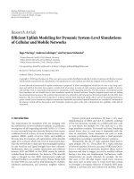
Figure 1: Finite state machine description of the proposed D-STAR
protocols, involving the transitions occurring among init, discovery,
regime,andoff phases.
2.4. Directive STAR MAC protocol
The proposed directive STAR (D-STAR) MAC protocol ex-
pands the STAR MAC concept to achieve a time-space syn-
chronization.
2
The network infrastructure is built up by
means of joining together bidirectional links; to allow com-
munications inside a WSN, each node sends to its neighbors
its own phase φ as it happens in STAR approach, while the
angular position is implicitly taken into account at the re-
ceiver and transmitter sides.
3
To give an exhaustive description of the D-STAR pro-
tocol, it is possible to refer to the state diagram given in
Figure 1. According to it, every node wakes up independently
of the other ones, entering an initial idle mode (init), in
which it remains for a time interval necessary to perform the
elementary CPU operations and to be completely switched
on (T
init, j
). Then it switches into the discovery phase where
it tries to recognize its neighbors and to establish a logical
synchronization with them. Within this phase, the operation
mode of jth node is duty cycled with a periodic succession of
listening and sleeping subperiods, whose durations are T
l, j
and T
s, j
,respectively.
4
For the sake of generality, it has been supposed that the
generic jth node has a specific frame period T
f , j
and duty
cycle δ
j
(and of course listening T
l,i
and sleeping T
s,i
subperi-
ods) with j
= 1, , N,whereN is the total number of nodes
2
It is worth noticing that this approach, like the STAR protocol, is mainly
suited for flat networks in which there are no cluster heads distributing a
time frame and for densely deployed networks with a number of neigh-
bors per node greater than ten [6].
3
Since there is not a common angular reference system, each node upon
the reception of a packet is able to identify the angular position of the
sender with respect to its own system; this information is stored and used
to transmit to that node.
4
The abrupt introduction of this operation mode allows a remarkable
power saving as an unnecessary long listening phase is avoided, while
more attention might be devoted to also minimize the setup latency.
4 EURASIP Journal on Wireless Communications and Networking
in the network. Moreover, it has been assumed that the wake
up time is randomly selected by each node.
To provide an affordable and robust approach, during the
initial setup (discovery) phase each node remains in a listen-
ing mode for a time interval equal to
T
setup
≥ 2max
j
T
f , j
. (8)
The minimum value for T
setup
has been chosen equal to
2max
j
{T
f , j
} since it has been assumed that T
init, j
≤ T
f , j
.
In the discovery phase, each node begins to broadcast one
hello message to each angular sector (i.e., the coverage area
within a certain side lobe) sending its ID and phase; then
it waits for a fixed time duration τ
s
in search of reply mes-
sages
5
and sw itches to the following angular sector, repeating
the procedure until T
setup
is expired. In particular, each node
sends the hello messageswithaperiod
T
broad
≤ min
j
T
l, j
. (9)
As a consequence, the number of hello messages sent by the
jth node during the discovery phase is equal to
N
broad
≥
T
f , j
min
i
T
l,i
N
s
, (10)
where N
s
is the number of nonoverlapping angular sectors
of the transmitter antenna.
6
The value of the phase φ sent
is strictly related to the time interval remaining to exit the
discovery phase and enter the duty-cycled mode.
It is worth noticing that as N
s
increases the cost of hello
messages transmission is predominant with respect to the
cost of the listening mode for the vast majority of hardware
platforms available on the market. This justifies a posteriori
the simplified exit condition from the setup phase.
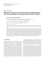
The overall messages exchange related to the discovery
phase is represented in Figure 2. In particular, it has been
assumed that Node A has four neighbors belonging to four
different angular sectors. Node A begins the channel sens-
ing procedure and then it sends one hello message per an-
gular sector. Upon the successful reception of this message,
each node adds Node A to the list of its own active neigh-
bors. The procedure is repeated until the discovery phase is
expired, that is, for a time interval T
setup
= 2T
f
.
7
In Figure 1
the transition from the discovery to the regime phase occurs
when the condition n
f
= N
fd
is satisfied, where n
f
is the
5
Once the communication is logically established with this node, the fol-
lowing hello messages sent to it in a unicast way are able to also reach the
other nodes within the same angular sector.
6
If no additional information is provided during the discover y phase, the
value of max
i
{T
f ,i
} mightbeestimatedbythegeneric jth node on the
basis of its own characteristics (i.e., max
i
{T
f ,i
}≡T
f ,j
)andthesameis
true for min
i
{T
l,i
} (i.e., min
i
{T
f ,i
}≡T
f ,j
). These values could be further
refined upon receiving hello messages from neighbor nodes containing
this information.
7
It implies that the hello message sending is repeated twice.
number of frame periods spent from the beginning of the
discovery phase and N
fd
represents its maximum value.
Once the discovery phaseisexpired,eachnodeentersthe
regime phase, according to Figure 1. The reference node then
sends hello messages in a unicast way to the neighbors be-
longing to different angular sectors, according to the phase
φ transmitted in previous hello message. In addition to that,
several hello messages are sent in background with the proper
period to unknown neighbors in the empty angular sector.
Upon the replying of a node, a logical channel is established
and jth node can adopt the unicast or the multicast ap-
proach, according to the STAR+ approach [6]. Again, the
transmitted phase value φ is the time interval after which the
sender claims to be again in the listening status, as previously
introduced in Section 2.3. It might be pointed out that the D-
STAR protocol is able to prevent the so-called deafness prob-
lem,
8
under the hypotheses that the transmitted phase values
φ are correct, the local clocks do not present a remarkable
time drift and the antenna switching is ideally performed.
The channel access is managed by means of the carrier
sense multiple access with collision avoidance (CSMA/CA)
scheme, as specified in [19]. Before transmitting a packet to-
ward a certain angular sector, a node first listens to the chan-
nel: if no transmitted packets are detected, it assumes that
the channel is idle and starts transmitting. Otherwise, it must
wait and try again to transmit in that sector after a random
time interval until a maximum number of attempts has been
reached. This mechanism is very effective in reducing colli-
sions, while the problem of hidden node [2] is stil l partially
unsolved [20].
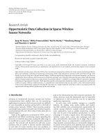
Each node remains in the regime phase until there is at
least one neighbor, otherwise if there are no active neigh-
bors (i.e., the number of empty angular sectors is equal to
N
s
)
9
it reenters the discovery phase in search of connectiv ity.
In Figure 3, the signaling occurring within the regime phase
is pointed out following the illustrative topology introduced
above. In particular, the channel sensing mechanism and the
unicast sending of one hello message per neighbor node are
shown, according to both the destination’s angular sector and
duty cycle.
To complete the protocol characterization, whenever a
node battery is depleted, this node turns off, entering an off
phase.
10
This is again represented in Figure 1.
3. PERFORMANCE ANALYSIS
To evaluate the performance of the proposed D-STAR
protocol, extensive numerical simulations have been con-
ducted over a realistic scenario in compliance with the pi-
8
This effect takes place when the transmitter fails to communicate to its
intended receiver, because the receiver’s antenna is oriented in a different
direction.
9
It might be due to the fact that a node could have joined the network
extremely late or even have changed its position.
10
This transition could indifferently occur starting both from the discovery
phase and from the regime phase.
Gianfranco Manes et al. 5
ChannelSensing
ChannelSensing
ChannelSensing
ChannelSensing
HEv
HelloMsgBroadcast
HEv
HelloMsgBroadcast
HEv
HelloMsgBroadcast
HEv
HelloMsgBroadcast
HelloReceived
CountCollision
RoutingTableUpdate
HelloReceived
CountCollision
RoutingTableUpdate
HelloReceived
CountCollision
RoutingTableUpdate
HelloReceived
CountCollision
RoutingTableUpdate
T
f
T
f
.
.
.
.
.
.
Node A Node B Node C Node D Node E
ChannelSensing
ChannelSensing
ChannelSensing
ChannelSensing
HEv
HelloMsgBroadcast
HEv
HelloMsgBroadcast
HEv
HelloMsgBroadcast
HEv
HelloMsgBroadcast
HelloReceived
CountCollision
RoutingTableUpdate
HelloReceived
CountCollision
RoutingTableUpdate
HelloReceived
CountCollision
RoutingTableUpdate
HelloReceived
CountCollision
RoutingTableUpdate
Figure 2: Message passing occurr ing within the discovery phase of the proposed D-STAR protocols.
lot site developed by EU Integrated Project “GoodFood”
[21]. The simulated system has been de veloped by means of
network protocol simulator (NePSing), that is, a C++ frame-
work specifically designed for modeling the evolution of a
time-discrete, asynchronous network [22]. The most rele-
vant simulation parameters are summarized in Tab le 1.The
adopted antenna model is an ideal switched beam antenna. A
group of almost nonoverlapping beams has been created that
together result in omnidirectional coverage, so that the pat-
terns’ main lobes are adjacent. The microcontroller at each
node is able to scan the channel according to the D-STAR
protocol, switching to the correct beam corresponding with
the user wishing to communicate at that time. Only a single
beam pattern is employed at any given time. In particular,
the antenna has been conceived so that to cover a fixed arc or
sector of, say, π, π/2, π/3, and π/4 radians, thus providing in-
creased gain over a restricted range of azimuths as compared
to an omnidirectional antenna. Besides, WSN nodes are sup-
posed to be deployed only in a 2D scenario.
The adopted approach has been conceived to mini-
mize the power consumption, thus enhancing the network
lifetime.
11
To this end, a duty-cycled operation and direc-
tive antennas have been introduced and properly managed
to allow full connectivit y through time-space synchroniza-
tion. However, the D-STAR protocol is also able to minimize
the setup latency, as the discovery phase duration T
setup
is up-
per bounded by twice the maximum frame period value, as
explained in (8).
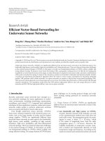
To give an insight on the protocol energy efficiency, in
Figure 4, the lifetime as a function of the number of network
nodes has been pointed out in the case of omnidirectional
antennas (i.e., the basic STAR MAC protocol), and directive
antennas with two or four angular sectors, respectively. The
remarkable gain provided by the introduction of directive
antennas could be noticed; in particular, it is a lmost equal to
4 or 16 in the case of two or four angular sectors, respectively,
in accordance with analytical predictions. Nevertheless, per-
formance gets worse as the number of nodes increases, due to
11
As to o ur p urpose, the network lifetime has been assumed in a strict sense,
that is, as the time interval after which the first node is turned off.
6 EURASIP Journal on Wireless Communications and Networking
UnicastManagement
ChannelSensing
ChannelSensing
ChannelSensing
ChannelSensing
ChannelSensing
HEv
HelloMsgUnicast
HEv
HelloMsgUnicast
OccupiedChannel
HEv
HelloMsgUnicast
HEv
HelloMsgUnicast
T
l
T
s
Node A Node B Node C Node D Node E
T
l
T
s
T
l
T
s
T
l
T
s
T
l
T
s
Figure 3: Message passing occurring within the regime phase of the proposed D-STAR protocols.
the presence of packet collisions that implies packets retrans-
missions and transmitted power wasting. It is not surpris-
ing that the network lifetime is extremely high,
12
as only the
MAC layer operations have been simulated, that is, the hello
message sending, thus with a very low network load. This
choice better highlights the benefits of the proposed scheme
with respect to the basic approach (i.e., with omnidirectional
antennas).
13
In Figure 5, the same comparisons have been performed
with respect to the duty cycle value which has been var-
ied over a commonly adopted range of [1%, 5%]. With-
out pointing out again the noticeable gain, it is possible to
highlight that lifetime remains constant no matter what the
dutycycle is, as the larger the listening time the greater the
receiving cost and the lower the collision probability.
12
For instance it is equal to two and a half years in the worst case.
13
However, to complete the present analysis, the D-STAR protocol might be
integrated in future works with the Network layer to take into account the
packet forwarding that is undoubtedly the most relevant cause of power
consumption.
Finally, in Figure 6, the network lifetime as a function of
the frame period duration T
f
is shown. Within a usual op-
eration range for T
f
from 10 seconds up to 90 seconds, the
lifetime has a linear increase, as the listening subperiod du-
ration T
l
is also proportional to T
f
and it mostly affects the
overall power consumption.
The energy efficiency of the proposed D-STAR protocol
can be evaluated by also focusing on the collision probability
that depends upon the node density and the presence of the
hidden nodes. The underlying CSMA/CA mechanism might
fail indeed if neighbor nodes get extremely close or if two or
more nodes not belonging to the same coverage area attempt
to transmit toward the same node.
To get an insight on this aspect, in Figure 7, the collision
probability as a function of the number of network nodes is
depicted, again in the case of omnidirectional antennas and
directive antennas with two, four, six, eight possible angular
sectors, respectively. It could be noticed that the adoption of
omnidirectional antennas minimizes the packets collisions,
even in the case of densely deployed nodes, while the con-
verse is true for directive antennas mostly due to the presence
Gianfranco Manes et al. 7
Table 1: Parameters values adopted within the numerical simula-
tion campaign.
Parameter Value
Monitored Area [m
2
] 25 × 25
Number of nodes
[10, , 50]
Number of angular sectors
[1,2,4,6,8]
Frame duration T
f
[s] [10, 25, 50, 75, 93]
Duty cycle δ [%]
[1, ,5]
Transmitted power [dBm]
0
Receiver attenuation [dBm]
−50
Receiver sensitivity [dBm]
−90
Transmitting antenna gain G
t
[0.5, 1, 2, 3, 4]
Receiving antenna gain G
r
[0.5, 1, 2, 3, 4]
Battery initial level [mAh]
2500
Cost of 1 hello packet
6 · 10
−5
transmission [mAh]
Cost of hello pkt reception/channel
2.777 · 10
−3
sensing [mA/s]
Cost of sleeping [mA/s] 2.97 · 10
−6
Maximum number of CSMA/CA
6
algorithm backoff attempts
Time duration of a channel
0.02
sensing attempt [s]
Hello packet size (payload) [B] 8
Transmission bit-rate [kb/s]
250
Packet error rate [%]
5
Simulated time interval [s]
86400
of hidden nodes, since the coverage area gets smaller in terms
of azimuth and an increasing number of nodes become invis-
ible.
14
However, as the angular resolution increases, a lower
number of nodes might overlap with a third node when
transmitting and the communication becomes really point-
to-point.Thiseffect is more evident in the case of directive
antennas with a number of possible angular sectors greater
than four, since a kind of spatial blindness occurs in the case
of lower values.
15
The adoption of a medium access scheme following a
CSMA/CA approach implies that a new channel sensing
is randomly scheduled whenever a channel is not detected
as idle. This allows for the avoidance of packet collision,
whilst reducing the link throughput. To conclude this anal-
ysis, Figure 8 points out the probability of finding the chan-
nel occupied as a function of the number of deployed nodes.
In this case the most conservative scheme, that is, the omni-
directional one, highlig hts the worst behavior for these pa-
rameters being compensated by a better collision probability,
while the opposite happens for more directional antennas.
14
It could be noticed that in any case the maximum value for collision prob-
ability remains lower that 2%.
15
This statement is true in the case of a symmetric link, that is, w ith the
same antenna at the receiver and transmitting sides. Otherwise, the per-
formance is limited by the antenna with the lower directivity.
0
5000
10000
15000
20000
25000
30000
35000
40000
45000
50000
55000
60000
65000
70000
75000
Network lifetime (days)
10 15 20 25 30 35 40 45 50
Number of nodes
Omnidirectional
N
= 2
N
= 4
Figure 4: Network lifetime as a function of the number of nodes
in the case of omnidirectional and directive antennas with π or π/2
main lobes for T
f
= 93 seconds and δ = 3%.
0
2500
5000
7500
10000
12500
15000
17500
20000
Network lifetime (days)
0.01 0.015 0.02 0.025 0.03 0.035 0.04 0.045 0.05
Dutycycle
Omnidirectional
N
= 2
N
= 4
Figure 5: Network lifetime as a function of the duty cycle δ in the
case of omnidirectional and directive antennas with π or π/2main
lobes for T
f
= 93 seconds and 50 nodes.
4. CONCLUSIONS AND FURTHER DEVELOPMENTS
The WSN application is widely considered as the most
promising solution for intelligent environments instrument-
ing, leading to novel communications paradigms. However,
this could be pursued by means of effective protocols design,
since sensor nodes present specific constraints, as far as the
limited resources, the low degree of mobility, and the unat-
tended operations.
8 EURASIP Journal on Wireless Communications and Networking
0
2500
5000
7500
10000
12500
15000
17500
20000
Network lifetime (days)
10 20 30 40 50 60 70 80 90
Time of frame (s)
Omnidirectional
N
= 2
N
= 4
Figure 6: Network lifetime as a function of the frame duration T
f
in the case of omnidirectional and directive antennas with π or π/2
main lobes for T
f
= 93 seconds and 50 nodes.
0
0.005
0.01
0.015
0.02
0.025
0.03
Collision probability
10 15 20 25 30 35 40 45 50
Number of nodes
Omnidirectional
N
= 2
N
= 4
N
= 6
N
= 8
Figure 7: Collision probability as a function of the number of nodes
in the case of omnidirectional and directive antennas with π, π/2,
π/3, and π/4 main lobes for T
f
= 93 seconds and δ = 3%.
This paper deals with both the sleep/active states power
management, as well as the introduction of directional an-
tennas and their integration within the communications
framework, following a cross-layer design. A novel MAC
layer protocol, namely, D-STAR is proposed, aiming at ex-
panding the capabilities of previously introduced STAR MAC
approach [6] toward the management of directive antennas,
without increasing the signaling overhead or affecting the
setup latency, but by achieving a reduction in energy con-
sumption.
0
0.005
0.01
0.015
0.02
0.025
0.03
0.035
0.04
0.045
0.05
0.055
0.06
0.065
0.07
0.075
0.08
Channel occupation probability
10 15 20 25 30 35 40 45 50
Number of nodes
Omnidirectional
N
= 2
N
= 4
Figure 8: Channel occupation probability as a function of the num-
ber of nodes in the case of omnidirectional and directive antennas
with π and π/2 main lobes for T
f
= 93 seconds and δ = 3%.
The D-STAR protocol has been characterized in terms
of functional characteristics, state transitions diagram repre-
sentation, and the related time charts for different use cases.
The overall communications protocol performance is pre-
sented, in terms of network lifetime gain, setup latency, and
collision probability, pointing out a remarkable gain with re-
spect to the basic approach endowed with omnidirectional
antennas.
Future developments of the present research activity
might include the protocol implementation and testing over
realistic user defined scenarios, like the ones proposed in
[21, 23], or the application to critical emergency operations
such as [24].
ACKNOWLEDGMENTS
This work was supported in part by the EU Integrated Project
FP6-IST-1-508774-IP “GoodFood” as well as by the EU Net-
work of Excellence FP6-IST-4-027738-NoE “CRUISE” and
EU STREP FP6-IST-045299-STREP “DustBot.”
REFERENCES
[1] I. F. Akyildiz, W. Su, Y. Sankarasubramaniam, and E. Cayirci,
“Wireless sensor networks: a survey,” Computer Networks,
vol. 38, no. 4, pp. 393–422, 2002.
[2] P. Mohapatra and S. Krishnamurthy, Ad Hoc N etworks Tech-
nologies and Protocols, Springer Science & Business Media,
New York, NY, USA, 2005.
[3] I.F.AkyildizandI.H.Kasimoglu,“Wirelesssensorandactor
networks: research challenges,” Ad Hoc Networks, vol. 2, no. 4,
pp. 351–367, 2004.
[4] A. Ha
´
c, Wireless Sensor Network Designs,JohnWiley&Sons,
New York, NY, USA, 2003.
Gianfranco Manes et al. 9
[5] S. Shakkottai, T. S. Rappaport, and P. C. Karlsson, “Cross-layer
design for wireless networks,” IEEE Communications Maga-
zine, vol. 41, no. 10, pp. 74–80, 2003.
[6] F. Chiti, M. Ciabatti, G. Collodi, D. Di Palma, R. Fantacci, and
A. Manes, “Design and application of enhanced communica-
tion protocols for wireless sensor networks operating in envi-
ronmental monitoring,” in Proceedings of IEEE International
Conference on Communications (ICC ’06), vol. 8, pp. 3390–
3395, Istanbul, Turkey, June 2006.
[7] D. Leang and A. Kalis, “Smart sensorDVBs: sensor network
development boards with smart antennas,” in Proceedings of
the International Conference on Communications, Circuits and
Systems (ICCCAS ’04), vol. 2, pp. 1476–1480, Chengdu, China,
June 2004.
[8] V. Srivastava and M. Motani, “Cross-layer design: a survey
and the road ahead,” IEEE Communications Magazine, vol. 43,
no. 12, pp. 112–119, 2005.
[9] K. Langendoen and G. Halkes, “Energy-efficient medium
access control,” Tech. Rep., />.html.
[10] C. E. Perkins, Ad Hoc Networking, Addison-Wesley, Boston,
Mass, USA, 2000.
[11] L. Breslau, D. Estrin, K. Fall, et al., “Adavance in network sim-
ulation,” Computer, vol. 33, no. 5, pp. 59–67, 2000.
[12] L. Bao and J. J. Garcia-Luna-Aceves, “Transmission scheduling
in ad hoc networks with directional antennas,” in Proceedings
of the 8th Annual International Conference on Mobile Comput-
ing and Networking (MOBICOM ’02), pp. 48–58, Atlanta, Ga,
USA, September 2002.
[13] A. Kalis and T. Dimitriou, “Fast routing in wireless sensor net-
works using directional transmissions,” International Journal
of Mobile Network Design and Innovation, vol. 1, no. 1, pp. 63–
69, 2005.
[14] IEEE standard 802.11: Wireless LAN Medium Access Control
(MAC) and Physical Layer (PHY) Specifications, IEEE Std.,
1999, />[15] A. El-Hoiydi, J D. Decotignie, C. Enz, and E. Le Roux,
“WiseMAC, an ultra low power MAC protocol for the
wiseNETwirelesssensornetwork,”inProceedings of the 1st In-
ternational Conference on Embedded Networked Sensor Systems
(SenSys ’03), pp. 302–303, Los Angeles, Calif, USA, November
2003.
[16] W. Ye, J. Heidemann, and D. Estrin, “An energy-efficient MAC
protocolforwirelesssensornetworks,”inProceedings of the
21st Annual Joint Conference of the IEEE Computer and Com-
munications Societies (INFOCOM ’02), vol. 3, pp. 1567–1576,
New York, NY, USA, June 2002.
[17] T. van Dam and K. Langendoen, “An adaptive energy-efficient
MAC protocol for wi reless sensor networks,” in Proceedings of
the 1st International Conference on Embedded Networked Sen-
sor Systems (SenSys ’03), pp. 171–180, Los Angeles, Calif, USA,
November 2003.
[18] G. Lu, B. Krishnamachari, and C. S. Raghavendra, “An adap-
tive energy-efficient and low-latency MAC for data gathering
in sensor networks,” in Proceedings of International Workshop
on Algorithms for Wireless, Mobile, Ad Hoc and Sensor Networks
(WMAN ’04), Santa Fe, NM, USA, April 2004.
[19] 802.15.4-2003—part 15.4: Wireless Medium Access Control
(MAC) and Physical Layer (PHY) Specifications for Low-Rate
Wireless Personal Area Networks (LR-WPANs), IEEE Std., Oc-
tober 2003, />[20] A. P. Subramanian and S. R. Das, “Using directional an-
tennas in multi-hop wireless networks: deafness and direc-
tional hidden terminal problems,” in Proceedings of the 13th
International Conference on Network Protocols (ICNP ’05),
Boston, Mass, USA, November 2005.
[21] “EU Integrated Project FP6-IST-1-508774-IP “GoodFood”,”
/>[22] T. Pecorella, “NePSing—Network Protocol Simulator ng,”
/>[23] “EU Networkof ExcellenceFP6-IST-4-027738-NoE“CRUISE”,”
/>[24] “EU STREP FP6-IST-045299-STREP “DustBot”,” http://www
.dustbot-project.org/.