Báo cáo hóa học: " Research Article Advanced Fade Countermeasures for DVB-S2 Systems in Railway Scenarios" ppt
Bạn đang xem bản rút gọn của tài liệu. Xem và tải ngay bản đầy đủ của tài liệu tại đây (1.34 MB, 17 trang )
Hindawi Publishing Corporation
EURASIP Journal on Wireless Communications and Networking
Volume 2007, Article ID 49718, 17 pages
doi:10.1155/2007/49718
Research Article
Advanced Fade Countermeasures for DVB-S2 Systems in
Railway Scenarios
Stefano Cioni,
1
Cristina P
´
arraga Niebla,
2
Gonzalo Seco Granados,
3
Sandro Scalise,
2
Alessandro Vanelli-Coralli,
1
and Mar
´
ıa Angeles V
´
azquez Castro
3
1
ARCES, University of Bologna, Via Toffano 2, 40125 Bologna, Italy
2
German Aerospace Center (DLR), Institute of Communications and Navigation, Postfach 1116, 82230 Wessling, Germany
3
Department of Telecommunications and Systems Engineering, Universitat Aut
`
onoma de Barcelona, Campus Universitari, s/n,
08193 Be llatera, Barcelona, Spain
Received 22 October 2006; Accepted 3 June 2007
Recommended by Ray E. Sheriff
This paper deals with the analysis of advanced fade countermeasures for supporting DVB-S2 reception by mobile terminals
mounted on high-speed trains. Recent market studies indicate this as a potential profitable market for satellite communications,
provided that integration with wireless terrestrial networks can be implemented to bridge the satellite connectivity inside railway
tunnels and large train stations. In turn, the satellite can typically offer the coverage of around 80% of the railway path with existing
space infrastructure. This piece of work, representing the first step of a wider study, is focusing on the modifications which may
be required in the DVB-S2 standard (to be employed in the forward link) in order to achieve reliable reception in a challenging
environment such as the railway one. Modifications have been devised trying to minimize the impact on the existing air interface,
standardized for fixed terminals.
Copyright © 2007 Stefano Cioni et al. This is an open access article distributed under the Creative Commons Attribution License,
which permits unrestricted use, distribution, and reproduction in any medium, provided the original work is properly cited.
1. INTRODUCTION
Satellite communications developed to a tremendous global
success in the field of analog and then digital audio/TV
broadcasting by exploiting the inherent wide-area coverage
for the distribution of content. It appeared a “natural” con-
sequence to extend the satellite services for point-to-point
multimedia applications, by taking advantage of the ability of
satellite to efficiently distribute multimedia information over
very large geographical areas and of the existing/potential
large available bandwidth in the Ku/Ka band. Particularly in
Europe, due to the successful introduction of digital video
broadcasting via satellite (DVB-S) [1], a promising techni-
cal fundament has been laid for the development of satel-
lite communications into these new market opportunities
using the second generation of DVB-S [2], commonly re-
ferred to as DVB-S2, as well as return channel via satellite
(DVB-RCS) [3] standards. Thus, for satellite systems cur-
rently under development and being designed to support
mainly multimedia services, the application of the DVB-S2,
for the high-capacit y gateway-to-user (forward) links and of
DVB-RCS for the user-to-gateway (return) links, is widely
accepted.
Complementing to satellite multimedia to fixed termi-
nals, people are getting more and more used to broadband
communications on the move. Mobile telephones subscrip-
tions have exceeded fixed line subscription in many coun-
tries. Higher data rates for mobile devices are provided
by new standards such as UMTS, high-speed packet access
(HSPA), prestandardized version of mobile WiMAX, and, in
case of broadcast applications, digital video broadcasting for
handhelds (DVB-H) [5].
At present, broadband access (e.g., to the Internet) and
dedicated point-to-point links (for professional services) are
primarily supplied by terrestrial networks. Broadband sat-
coms services are still a niche market, especially for mobile
users. In this context, many transport operators announce
the provision of TV services in ships, trains, buses, and air-
crafts. Furthermore, Internet access is offered to passengers.
With IP connectivity, also radio interfaces for GSM can be
implemented for such mobile platforms by using satellite
connectivity for backhauling.
Thus, DVB-S2/RCS appears an ideal candidate to be in-
vestigated for mobile usage, as it can ideally combine digital
TV broadcast reception in mobile environments (airTV, lux-
ury yachts, trains, e tc.) and IP multimedia services.
2 EURASIP Journal on Wireless Communications and Networking
However, the aforementioned standards have not been
designed for mobile use. Collective terminals installed in a
mobile platform, such as train, ship, or aircraft, are exposed
to a challenging environment that will impact the system per-
formance considering the current standard in absence of any
specific provision.
Mobile terminals will have to cope in general with strin-
gent frequency regulations (especially in Ku band), Doppler
effects, frequent handovers, and impairments in the synchro-
nization acquisition and maintenance. Furthermore, the rail-
way scenario is affec ted by shadowing and fast fading due
to mobility, such as, for example, the deep and frequent
fades due to the presence of metallic obstacles along electri-
fied lines providing power to the locomotive
1
[6] and long
blockages due to the presence of tunnels and large train sta-
tions. This suggests that hybrid networks, that is, interwork-
ing satellite and terrestrial components, are essential in order
to keep service availability.
In this context, this paper is focused on proposing and
evaluating fade countermeasures to compensate the impact
of fade sources in the railway scenario, that is, shadowing,
fast fading, and power arches, excluding tunnels which will
be address at a later stage. In particular, antenna diversity and
packet level forward error correction (FEC) are investigated.
The rest of the paper is organized as follows: Section 2
discusses the potential of opening the current DVB-S2/RCS
standards to provide mobile services efficiently. Section 3
presents the peculiarities of the trains’ scenario and discusses
the different aspec ts that can impact the system performance.
Section 4 describes the fade countermeasures proposed in
this paper. Section 5 introduces the simulation platform s in
which the proposed fade countermeasures are evaluated and
Section 6 presents and discusses the obtained results. Finally,
Section 7 draws the conclusions of this work.
2. THE VISION: A NEW DVB-S2/RCS STANDARD FOR
MOBILE COLLECTIVE TERMINALS
The large capacity of DVB-S2/RCS systems can efficiently ac-
commodate broadcast services (e.g., digital TV) and unicast
IP multimedia interactive services to fixed terminals. How-
ever, the increasing interest on broadband mobile services
suggests that the natural evolution of DVB-S2/RCS standard
to cover new market needs goes towards the support of mo-
bile terminals.
In particular, the required antenna performance in Ku
(10–12 GHz) and Ka (20–30 GHz) bands focuses the mar-
ket opportunities of DVB-S2/RCS onto mobile terminals in
collective transportation means. Actually, transport opera-
tors are starting to announce the provision of TV services in
ships, tr ains, buses, and aircrafts, and broadband IP connec-
tivity, for passengers. For the specific case of trains, broad-
band services can provided using satellite systems, cellular
connectivity or dedicated trackside installations.
1
Hereafter referred to as “ power arches,” for the sake of brevity.
As summarized in Tabl e 1, none of these alternatives
alone represents a satisfactory solution. As a matter of fact,
deployed or upcoming commercial services are based on
combinations of different access technologies. In this light,
a satellite access based on an open standard can have very
significant benefits in terms of interoperability (achieved for
DVB-S2/RCS through SatLabs Qualification Program) and
competition, thus benefiting from availability of fully com-
patible terminals from multiple vendors and reducing the
cost of terminals.
However, the aforementioned DVB standards have been
designed for fixed terminals. To cope with these new market
opportunities, DVB TM-RCS has investigated how the cur-
rent DVB-RCS standard could be applied to mobile applica-
tions. A white paper on the applicability of DVB-RCS to mo-
bile services was prepared and a technical annex was added
to the implementation guidelines document [4]. This annex
states the boundary conditions and limitations under which
the existing standard could be used in mobile environment,
considering the impact of mobility in terminal synchroniza-
tion and demodulator performance in forward and return
links. Furthermore, a survey on applicable regulations and a
brief analysis on DVB-RCS features that can be used for mo-
bility management are provided, the latter referring to inter-
beam handover only.
Thus, the DVB-RCS guideline cannot support the full
adaptability to mobile environments and hence the applica-
ble services and scenarios happen to be very limited. Fur-
thermore, additional issues related to mobility are not fully
solved, such as handling of nonline-of-sight (nLOS) channel
conditions, which will require the interworking with terres-
trial gap fillers in the railway scenario due to the presence of
tunnels. In addition, even if DVB-RCS features to be applied
for mobility management are analyzed, a determined m ech-
anism or protocol should be specified in order to ensure in-
teroperability. Finally, the impact of control signals loss (due
to deep fades or handover) is not negligible. For instance, the
loss of terminal burst time plan (TBTP) tables damages the
operation of the resource management, essential in the re-
turn link for a coordinated access to the radio resources.
As a matter of fact, mobile services could be more effi-
ciently supported if the present standards could be improved
for mobile scenarios. The reopening of the standard
2
would
allow for the specification of methods for improving the link
reliability in mobile environments (e.g., packet level FEC),
handover protocols, interfaces to terrestrial gap fillers (even
using terrestrial mobile technologies), improved mobility-
aware signalling and resource m anagement, and so forth.
In this context, a number of R and D initiatives are on-
going with the aim at investigating enhancements of the
DVB-S2/RCS standards for the efficient support of mobil-
ity. Among those, the SatNEx network of excellence has set
up a dedicated working group investigating different aspects
related to mobility in DVB-S2/RCS. The first results of this
activity in the field of forward link reliability for the rail-
way scenario are presented in this paper. For the return link,
2
Envisaged at the time of writing.
Stefano Cioni et al. 3
Table 1: Pros and cons of different solutions for providing broadband services on trains.
Type of
technology
Examples Pros Cons
Satellite
DVB-S2/RCS
Proprietary systems,
for example, ViaSat
(i) No new trackside
infrastructure—quick to
deploy, project costs may be
lower on long distance routes
(i) Available tracking antennas and
efficient satcom modems expensive
(ii) Dedicated bandwidth available (ii) High variable cost per MB
(iii) Performance easy to predict
depending on satellite visibility
(iii) Return bandwidth constrained
by antenna size
(iv) Not affected by borders—good
for international trains
(iv) Satellite visibility seriously
restricted on some rail routes
Cellular
GPRS
EDGE
UMTS
HSUPA/HSDPA
(EV-D O)
(i) Equipment is small and cheap (i) Geographic coverage of UMTS
limitedforyearstocome
(ii) Usage is cheap (50–75 C per month
flat rate)
(ii) Coverage of railway lines often
worse than roads
(iii) Data rates improving year on year (iii) GPRS/EDGE not really fast enough
(iv) Competitive supply—3 or 4 network
operators in most countries
(iv) Inverse relationship between
throughput and train speed
(v) No QoS guarantees—affected by
network congestion at peak times
(vi) Organized country by country—data
roaming charges are punitive
Trackside
Flash OFDM
IEEE 802.11
IEEE 802.16 (WiMAX)
(i) High data rates possible (i) Existing standards not designed to
support fast-moving terminals
(ii) Can control bandwidth and QoS (ii) Proprietary equipment is more
expensive
(iii) On-train equipment relatively
inexpensive
(iii) No suitable public services yet in
licensed bands—will licence-holders be
allowed to provide mobile services?
(iv) No volume-related usage costs (iv) Licence-exempt bands are low power,
thus limited range
(v) Infrastructure deployment (especially
trackside) is expensive and time consuming
analogue solutions have to be devised, which are however not
in the scope of the present work.
3. THE RAILWAY SCENARIO, A CHALLENGING
ENVIRONMENT
3.1. Overview
The land mobile satellite channel (LMSC) has been widely
studied in the literature [7]. Several measurement campaigns
have been carried out and several narrow and wideband
models have been proposed for a wide range of frequencies,
including Ku [8]andKa[9] bands. Nevertheless, for the spe-
cific case of the railway environment, only few results are
presented in [10] as a consequence of a limited trial cam-
paign using a narrowband test signal at 1.5 GHz, performed
more than 10 years ago in the north of Spain. These results
represent a very interesting reference, although no specific
channel model has been extracted from the collected data.
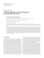
After an initial qualitative analysis, the railway environment
appears to differ substantially with respect to the scenarios
normally considered when modelling the LMSC. Excluding
railway tunnels and areas in the proximity of large railway
stations, one has to consider the presence of several metallic
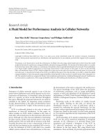
obstacles like power arches (Figure 1, left u ppermost), posts
with horizontal brackets (Figure 1, left lowermost), which
may be often grouped together (Figure 1, rightmost), and
catenaries, that is, electrical cables, visible in all the afore-
mentioned figures.
The results of direct measurements performed along the
Italian railway and aiming to characterize these peculiar ob-
stacles are reported in [6] and references herein. In summary,
4 EURASIP Journal on Wireless Communications and Networking
Figure 1: Nomenclature of railway specific obstacles.
the attenuation introduced by the catenaries (less than 2 dB)
and by posts with brackets (2-3 dB) is relatively low and can
be easily compensated by an adequate link margin. On the
other hand, the attenuation introduced by the power arches
goes, depending on the geometry, the radiation pattern of the
RX antenna, and the carrier frequency, down to values much
greater than 10 dB.
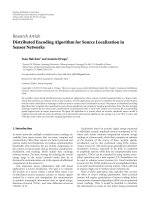
3.2. Modelling
Even if the layout and exact geometry of such obstacles can
significantly change depending on the considered railway
path, it tur ned out from previous works that the attenuation
introduced by these kind of obstacles can be accurately m od-
elled using knife-edge diffraction theory [11]: in presence of
an obstacle having one infinite dimension (e.g., mountains
or high building s), the knife-edge attenuation can be com-
puted as the ratio between the received field in presence of
the obstacle and the received field in free space conditions. In
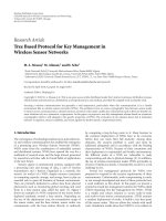
the case addressed here, as shown in Figure 2 (left), the obsta-
cle has two finite dimensions, and the received field is hence
the sum of the contributions coming from both sides of the
obstacle. Therefore, the resulting attenuation can be written
as follows:
A
s
(h)
=
1
√
2G
max
G
α
1
(h)
∞
Kh
e
−j(π/2)v
2
dv
+ G
α
2
(h)
K(h−d)
−∞
e
−j(π/2)v
2
dv
,
K
=
2
λ
a + b
a · b
,
(1)
where λ is the wavelength, a is the distance between the re-
ceiving antenna and the obstacle, b is the distance between
the obstacle and the satellite, h is the height of the obstacle
above the line-of-sight (LOS), and d is the width of the ob-
stacle. Finally, the usage of a directive antenna with radiation
pattern G(α) has to be considered. This implies an additional
attenuation due to the fact that whenever the two diffracted
rays reach the receiving antenna with angles α
1
and α
2
as
shown in Figure 2(left), the antenna shows a gain less than
the maximum achievable (G
max
) and depending on the vari-
able h, which is directly related to the space covered by the
train.
In absence of a channel model directly extracted from
measurements in the railway environment, it is a common
practice to model the so-called “railroad satellite channel”
by superimposing (i.e., multiplying) the statistical fades re-
produced by a Markov model (see [8, 9]) with the space-
periodic fades introduced by the electrical trellises obtainable
by means of the above equation. Values of the parameters
in Figure 2, as well as the space separation between subse-
quent electrical trellises, depend on the considered railway.
Finally, the considered receiving antennas are modelled with
high directivity in order to achieve large gain and at the same
time to reduce the received multipath components with large
angular spread. Hence, as reported in [12], the key parame-
ter becomes the antenna beamwidth which describes in the
frequency domain the Doppler power spectrum density of
the satellite fading channel. In this paper, the highly direc-
tive antennas are modelled with the reasonable value of the
beamwidth in the order of 5 degrees.
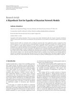
3.3. Need for fade countermeasures and gap fillers
The periodical fading events induced by power arches (PA)
result in a physical error floor that limits the performance of
the DVB-S2 system to unacceptable quality of service (QoS)
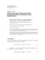
levels. In Figure 3, the baseband frame (BBFRAME) error
rate is reported in LOS conditions, for train speed equal to
300 km/h, and in the presence of power arches, when the re-
ceiver has only one receiving antenna and does not adopt
any packet level FEC technique. The error floor value is
about 0.0117, corresponding to the ratio between the du-
ration of PA induced fading events, that is, 6 msilliseconds
at 300 km/h, and the time between two fading events, that
is, 600 msilliseconds at 300 km/h. Considering the case of
27.5 M baud, the DVB-S2 BBFRAME duration is less than
1 msillisecond, therefore when the receiving antenna is ob-
scured by a power arch, transmitted packets are completely
lost unless fade countermeasures are adopted.
4. ADVANCED FADE COUNTERMEASURES
System designers can resort to different approaches to coun-
teract deep fading conditions and to guarantee an acceptable
QoS level. A possible classification of fade countermeasure is
between those techniques that need a return channel (from
the user to the network) to require a change in the transmis-
sion mode or a retransmission of the lost information, and
those that do not rely on a return channel and are therefore
more suitable for unidirectional delivery, such as multicast
or broadcast applications. The latter class of techniques is of
great interest for the collective railway application considered
in this work, for which return channel-based approaches,
such as automatic repeat request (ARQ) or adaptive coding
and modulation (ACM) techniques, are not doable. In par-
ticular, antenna diversity and packet level FEC techniques are
considered in the following.
Stefano Cioni et al. 5
b
hh-d
E
2
/E
0
a
E
1
/E
0
v
α
1
α
2
(a)
−45
−40
−35
−30
−25
−20
−15
−10
−5
0
5
Attenuation (dB)
−2.5 −2 −1.5 −1 −0.500.511.52 2.5
h (m)
0.6m
0.4m
0.2m
d
= 0.4m,a = 2.5m
(b)
Figure 2: Knife-edge diffraction model applied to the railway sce-
nario and possible attenuation caused by power arches at Ku band
for different antenna diameters.
4.1. Antenna diversity
The adoption of multiple receiving antennas to counteract
power arch obstructions in railway environment has been re-
cently proposed and investigated in [13, 14]. Antenna diver-
sity is used to provide different replica of the received signal
to the detector for combination or selection. If the receiving
antennas are sufficiently spaced, the received signals fade in-
dependently on each antenna thus providing multiple diver-
sity branches that can be linearly or nonlinearly combined to
improve detection reliability. There are mainly three types of
linear diversity combining approaches: selection, maximal-
ratio, and equal-gain combining. Considering two receiving
1E −04
1E
− 03
1E
− 02
1E
− 01
1E +0
BBFRAME error rate
13579111315171921
E
b
/N
0
(dB)
1/2 - QPSK (LOS, FAST, noPA)
2/3 - 8PSK (LOS, FAST, noPA)
3/4 - 16APSK (LOS, FAST, noPA)
5/6 - 16APSK (LOS, FAST, noPA)
1/2 - QPSK (LOS, FAST, PA)
2/3-8PSK(LOS,FAST,PA)
3/4 - 16APSK (LOS, FAST, PA)
5/6 - 16APSK (LOS, FAST, PA)
Power arches floor
Figure 3: BBFRAME error rate for DVB-S2 in the presence of
power arch blockage events. LOS propagation conditions and train
speed set to 300 km/h.
antennas, and assuming perfect compensation of time delays
of the two replicas, the combined signal can be written as
r
c
(t) = w
1
r
1
(t)+w
2
r
2
(t), (2)
where w
i
and r
i
(t), i = 1, 2, are the combing weights and
the received signals, respectively. The received signals at each
antenna is
r
i
(t) = α
i
s
0
(t)+n
i
(t), (3)
where s
0
(t) is the t ransmitted signal, α
i
is the time variant
fading envelope over the ith antenna, and n
i
(t) is the thermal
noise.
The simplest combining scheme is the signal selection
Combining (SC), in which the branch-signal with the largest
amplitude or signal-to-noise ratio (SNR) is the one selected
for demodulation. In this case, w
i
will be 1 or 0 if the
ith power branch is the largest or the smallest, respectively.
Clearly, SC is bounded by the performance of the single re-
ceiving antenna in absence of fading, that is, there is no di-
versity gain when the two antennas experience good chan-
nel conditions at the same time. Maximum-ratio combin-
ing (MRC), although requiring a larger complexity at the
receiver, allows for the exploitation of the diversity gain. In
fact, MRC scheme provides for the maximum output SNR.
According to the optimum combination criter ion, the signal
weights are directly proportional to the fading amplitude and
inversely proportional to the noise power, N
i
, as follows:
w
i
=
α
i
N
i
. (4)
Another technique, often used because it does not require
channel fading strength estimation, is equal gain combining
6 EURASIP Journal on Wireless Communications and Networking
(EGC) in which the combination weights are all set to one,
thus leading to a simpler but suboptimal approach. Clearly,
SC and MRC (or EGC) represent the two extremes in diver-
sity combining strategy with respect to the complexity point
of view and the number of signals used for demodulation
process. Furthermore, the classical combining formula can
be gener a lized for nonconstant envelope modulations such
as 16-APSK or 32-APSK (amplitude and phase shift keying)
and integrated with the soft demodulator that computes the
channel a posteriori information to feed the low density par-
ity check (LDPC) FEC decoder. The maximum likelihood a
priori information for a single receiver antenna given by
log
Pr
b
i
= 0 | r
k
Pr
b
i
= 1 | r
k
=
log
s
i
∈S
0
exp
−
r
k
− α
k
s
i
2
/N
0
s
i
∈S
1
exp
−
r
k
− α
k
s
i
2
/N
0
(5)
can be extended for L receiving antennas, according to the
MRC principle, as follows:
log
Pr
b
i
= 0 | r
k
Pr
b
i
= 1 | r
k
=
log
s
i
∈S
0
exp
−
L
p=0
r
p
k
− α
p
k
s
i
2
/N
p
0
s
i
∈S
1
exp
−
L
p=0
r
p
k
− α
p
k
s
i
2
/N
p
0
,
(6)
where r
k
is the received sample at time k, α
k
is the true or
the estimated channel coefficient, and S
0
and S
1
are the sets
of symbols which have “0” or “1” in the ith position, respec-
tively.
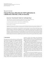
In the configuration proposed in this work, we adopt
MRC combining with two antennas. The antennas are placed
on the same coach so as to reduce the costs of installa-
tion and the connection length. The antenna spacing is cho-
sen as a function of the distance b etween two consecutive
power arches so as to guarantee that only one antenna at
a time can be obscured. Accordingly, the distance between
the two antennas is about 15 m. Considering the maximum
train speed (about 300 km/h), this translates into the fact
that power-arch blockage on a single antenna lasts for about
7 msilliseconds, and it hits the second antenna after a bout
180 msilliseconds. Therefore, it is reasonable to assume that
there is enough time for the combining circuit to react and
maintain constant signal connection. A drawback of this ap-
proach is that the receiving chain w ill be duplicated in or-
der to maintain connection and avoid frequent reacquisitions
process with the consequent loss of packet. As proposed in
[14], the solution which considers the presence of a second
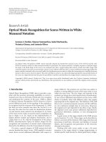
receiving antenna is depicted in Figure 4.Thegrayblocks
represent the subsystems that need to be duplicated in the
two antenna case. Further details on the digital receiver are
described in Section 5.1.
4.2. Packet level FEC
4.2.1. The concept of packet level FEC
Reliable transmission occurs when all recipients correctly re-
ceive the transmitted data. This target can be achieved by op-
erating at different layers of the protocol stack and in dif-
ferent ways. Retransmission techniques allow that lost pack-
ets are retransmitted to the receivers, while packet level FEC
schemes create redundant packets that permit to reconstruct
the lost ones at the receiver side, with a very beneficial in-
put on the final end-to-end delay. In fact, as detailed in [15],
the additional delay introduced by packet level encoding and
decoding is always lower than the delay deriving from any
retransmission scheme.
Regarding the retransmission schemes, efficient proto-
cols should limit the use of acknowledgement- (ACK-) based
mechanisms because they introduce heavy feedback traffic
towards the sender, thus increasing the congestion of reverse
link that, typically, has a reduced capacity with respect to
forward link. Negative acknowledgement- (NACK-) based
approaches are hence particularly interesting. In combina-
tion with (or in alternative to) the traditional retransmission
schemes, packet level FEC can be added on top of physical
layer FEC, in order to achieve the same level of reliability with
a reduced number of retransmissions. This might be partic-
ularly useful if resources on the return link need to be saved
(smaller number of NACKs or no NACKs are needed at all),
or when multiple lost packets are recovered with the retrans-
mission of a lower number of redundant packets. Basically,
h redundancy packets are added to each g roup of k informa-
tion packets, thus resulting in the transmission of n
= k + h
packets. These packets are finally transferred to the physi-
cal layer, which adds independent channel coding to each of
them. This principle is described in Figure 5.
At the physical layer, the bits affected by low noise lev-
els can be corrected by the physical layer FEC, so that the
related packets are passed to the higher layer as “correct.” If
the noise level exceeds the correcting capability of the phys-
ical layer, the received bit cannot be properly decoded, but
the failure to decode can be usually detected with a very high
reliability. Since erroneous packets are not propagated to the
higher layers, we have an erasure channel. The system can use
the redundancy packets to recover these erasures. By using
maximum distance separable (MDS) codes, like the Reed-
Solomon, it is possible to reconstruct the original informa-
tion if at least k out of n packets are correctly received. There-
fore, the receiver can cope with erasures, as long as they result
in a total loss not exceeding h packets, independently from
where the erasures occurred. LDPC codes and their deriva-
tions might be also used because of their low complexity and
greater flexibility, thus permitting to encode larger files, al-
though a small inefficiency, depending on the code design
and typically around 5%–10%, will be taken into account.
If packet level FEC is implemented at IP or data link layer,
very near to the physical channel, no change in the trans-
port and network layers protocols and in the physical layer
are necessary. This solution presents the additional advantage
that it can be adapted to the propagation channel conditions
Stefano Cioni et al. 7
Frame
synch
Received
signal
from
antenna no. 1
Matched
filter
Symbol
sampling
DeMUX
Data
Buffer
Frequency
acquisition
Timing
recovery
Preamble /
pilots
Noise level
estimation
N
1
0
θ
1
0
α
1
k
θ
1
0
θ
1
k
Digital
AGAC
Buffer
Lock
detector
Freq./phase
tracking
Signal
combiner
Hard/soft
demodulator
De-
interleav er
LDPC/BCH
decoder
From second
antenna
Figure 4: Receiver block diagram with antenna diversity.
n packets
k data packets (group) h redundancy packets
12
··· kk+1 ··· k + h Data link/IP layer
Channel coding
12
··· kk+1 ··· k + h Physical layer
Transmission
Figure 5: Packet level FEC principle.
by choosing n, so that the interleaver size is long enough to
compensate the channel outages. However, different protec-
tion for individual transfers (e.g., specific files) is not possi-
ble (although different QoS classes may be supported), extra
memory is required, and additional delays must be properly
handled.
For the forward link, the usage of packet level FEC is
especially powerful in allowing online variable coding ap-
proaches, which can be fine tuned in a closed-loop approach.
Based upon the “history” of the link, appropriate redun-
dancy can be easily added. Packet level FEC has then impact
on different layers.
(i) The requirements on control loops can be lessened, for
example, power control and or adaptive coding and
modulation control, if a loss of up to h packets can tol-
erated.
(ii) The typical fade structure of a link can be measured
and accordingly coding with the correct profile added.
(iii) Different QoS classes with different redundancy pro-
files can be supported. Furthermore, redundancy
packets for low-priority traffic can be put in a special
queue, which is served only if free capacity is available
and, in turn, increased redundancy can be sent during
handovers, minimizing the overall probability of lost
packets.
(iv) Different IP-based access methods can be used in par-
allel, improving the link reliability if different redun-
dancy is sent via different access methods.
4.2.2. The GSE-FEC method
When moving to the concrete applicability of this scheme to
the scenario under consideration, even though the fact that
IP packets have three sizes that are the most common ones,
the fact that IP packet size can actually take any value up
to a maximum value (typically 64 Kbytes) represents a clear
8 EURASIP Journal on Wireless Communications and Networking
IP packets
FEC matrix
GSE
encapsulation
BBFRAME assembly
using one or several
GSE units
BBFRAME
padding
BBFRAMEs
Figure 6: Steps involved in GSE-FEC.
difficulty in applying packet level FEC (PL-FEC). The funda-
mental difficulty comes from the fact that most codes take as
input a fixed amount of data, from which they compute the
redundancy bytes. As a given number of IP packets corre-
spond to a variable amount of data depending of their sizes,
codes needing a fixed amount of data cannot be directly ap-
plied. One possible solution is to use codes that can be eas-
ily adapted to different input sizes; however, this comes at
the price of a much more complex encoding and decoding
process. Another solution has been proposed in the DVB-H
standard [16]. In this case, units of constant length are built
by interleaving IP packets and, therefore, codes with fixed in-
put size can be easily applied. It is worth noting that those
units are not built by concatenating IP packets but by inter-
leaving them. However, interleaving is this case must not be
understood as it is typical in physical layer coding, where it
means that data is written in one direction in a matrix and
it is read in the orthogonal direction for transmitting. In PL-
FEC, we understand interleaving as computing the redun-
dancy in an orthogonal direction to the writing direction of
the data; however, in this case the writing and reading direc-
tions coincide. This kind of interleaving is advantageous be-
cause the redundancy is computed across a large number of
packets. Thus, a fade event may destroy one or several pack-
ets but not the majority of them, assuming that the system
is well dimensioned, so the added redundancy can effectively
help in recovering the destroyed packets.
DVB-H also provides a solution for encapsulating the
coded IP packets for transmission over DVB-T. The solution
is based on the use of multiprotocol encapsulation (MPE)
combined with MPEG. Although it would be possible to
adapt the same approach for DVB-S2, it presents a number
of dr awbacks, such as lack of flexibility, low encapsulation
efficiency, delay constraints. A new encapsulation protocol
call generic stream encapsulation (GSE) has been recently de-
fined [17]. It is a very flexible protocol applicable to several
physical layer standards. It overcomes most of the limitations
of MPE-MPEG. GSE is especially suitable for transmitting IP
packets through the generic stream interface mode of DVB-
S2, and it has been proposed for the second generation of
Terrestrial digital video broadcasting (DVB-T2) as well. GSE
also efficiently support s the ACM functionalities of DVB-S2
and facilitates the provision of QoS guarantees because it re-
duces the constraints on the scheduling operation.
It can be deducted from the previous discussion that the
implementation of PL-FEC consists of two main processes:
the encoding the IP packets and, second, the encapsulation
of the result of the encoding process in order to adapt it to
the underlying transmission system. In DVB-H, the first pro-
cess consists in arranging the IP packets in a mat rix (here-
after called FEC matrix) and applying a Reed-Solomon code,
while the second process employs MPE-MPEG. The whole
implementation is called MPE-FEC in DVB-H. Our proposal
for DVB-S2 is based on keeping the same first process as in
DVB-H, whereas it employs GSE in the second process. This
proposal for applying PL-FEC in DVB-S2 is named GSE-
FEC.
A block diagram of GSE-FEC is depicted in Figure 6.The
incoming IP packets are arranged in the so-called FEC ma-
trix, where also the packet-level redundancy is added. The
filling of the FEC matrix and the encoding are done in the
same way as in DVB-H. For the sake of completeness, this
will be briefly described below. Next, each IP packet is en-
capsulated using GSE, and this represents one of the novel
aspects of our proposal. Each IP packet may be fragmented
into several GSE units or it may also be sent unfragmented.
Subsequently, the maximum number of GSE units that can
be fitted inside a BBFRAME is concatenated and introduced
in the BBFRAME. The size of the BBFRAME depends on the
combination of coding rate and modulation scheme (MOD-
COD) adopted by the DVB-S2 modem, so the number of
GSE units that can be concatenated also depends on the
MODCOD. By making the GSE units small enough to have
the required flexibility, but large enough in order not to pe-
nalize encapsulation efficiency, this method provides an easy
mechanism to adapt the output of the packet-level FEC to the
variations of the physical layer. Moreover, note that padding
is not applied inside the GSE unit but only at BBFRAME level
if the size of the BBFRAME does not coincide with that of the
concatenation of the GSE u nits.
The IP packets are placed one after another along the
columns of the FEC mat rix, see Figure 7. Each IP packet may
be split among two or more columns. Only the first block of
the matrix, from column 1 to 191, can be filled in with IP
packets. The second block of the matrix, from column 192 to
255, carries the redundancy information, which is computed
by a Reed-Solomon (255,191) code applied to the first block
on a row basis. Each column in the second block is encap-
sulated individually using GSE, whereas in the first block the
GSE encapsulation is performed on an IP packet basis. In the
baseline operation, padding is only applied in the first block
to account for the fact that an additional IP packet may not
be fitted without overrunning the 191 columns and all 64 re-
dundancy columns are transmitted. The code can be made
weaker (i.e., with higher rate) by puncturing some of the re-
dundancy columns, which are then not transmitted and are
considered as unreliable bytes in the decoding process. The
code can also be made more robust (i.e., with lower rate)
by padding with zeros columns in the first block and, hence,
leaving less space for IP packets. The padded columns are not
transmitted but they are used in the encoding process. In the
decoding process, they are considered as reliable.
Stefano Cioni et al. 9
Coding direction
Writing direction
FEC matrix
1 2 3 188 189 190 191 192 193 254 255
··· ···
Data submatrix Redundancy submatrix
IP packet encapsulation with GSE Percolumn GSE encapsulation
Column size
IP packet 1
IP packet 2 IP packet 1 (cont.)
IP packet 3 IP packet 2 (cont.)
Padding Last IP packet (cont.)
Padding
Padding
Padding
1st redundancy column
2nd redundancy column
Punctured column
Punctured column
Figure 7: Arrangement of IP packets for FEC encoding.
After GSE encapsulation, the GSE packets are introduced
in BBFRAMEs and transmitted. On the receive side, erro-
neous BBFRAMEs are detected by checking the CRC. The
receiver reconstructs the FEC matrix and marks any column
that is totally or partially received by means on an erroneous
BBFRAME as unreliable. Finally, if the reconstructed FEC
matrix has no more than 64 unreliable columns, the code
can correctly compute all bytes in the matrix. If there are
more than 64 unreliable columns, the code cannot correct
anything, and only those columns received by means of cor-
rectBBFRAMEswillbecorrect.
5. SIMULATION SCENARIOS
In the following, the simulation platforms used to evaluate
the performance of DVB-S2 with advanced fade countermea-
sures in the railway environment as described in Section 3 are
duly detailed.
5.1. Advanced physical layer simulation platform
To cover a rather large set of spectral efficiency, four MOD-
CODs have been considered: 1/2-QPSK, 2/3-8PSK, 3/4-
16APSK, and 5/6-16APSK. The LOS channel condition
(Rice factor equal to 17.4 dB) and the train speed equal to
300 km/h have been simulated. Equally spaced power arches
with a separation of 50 m have been included in some sce-
narios, with a duty cycle of 1%, corresponding to a width of
0.5 m in accordance with Figure 2. The symbol rate was fixed
to 27.5 Mbaud.
The considered DVB-S2 physical layer transmitter [2]is
depicted in Figure 8. A continuous stream of MPEG pack-
ets passes through the mode adaptation which provides
input stream interfacing. This data flow is passed to the
merger/slicer that, depending on the applications, allocates
a number of input bits equal to the maximum data field ca-
pacity. In this way, user packets are broken in subsequent
data fields, or an integer number of packets are al located in
it. Then, a fixed length base-band header (BBHEADER) of
80 bits is inserted in front of the data field, describing its for-
mat. For example, it reports to the decoder the input streams
format, the mode adaptation type and the roll-off factor.
The efficiency loss introduced by this header varies from
0.25% to 1% for long and short codeword lengths, respec-
tively. The role of stream adaptation is to provide padding
when needed, in order to complete a constant length frame,
and scrambling. Padding is applied when the user data avail-
able for transmission are not sufficient to completely fill a
BBFRAME, or w hen more than one packet have to be allo-
cated in a BBFRAME. The built frame is randomized using a
scrambling sequence generated by the pseudorandom binary
sequence described by the polynomial (1 + X
14
+ X
15
). After
this scrambling, each BBFRAME is processed by the forward
error correction (FEC) encoder which is carried out by the
concatenation of a Bose-Chaudhuri-Hocquenghem (BCH)
outer code and an LDPC inner code. Available code-rates
for the inner code are 1/4, 1/3, 2/5, 1/2, 3/5, 2/3, 3/4, 4/5,
5/6, 8/9, and 9/10. Depending on the application area, code-
words can have length N
LDPC
= 64800 bits or 16200 bits. In
the following, the case of 64800 bits is considered. Regard-
ing the modulation format, each coded BBFRAME can be
mapped onto QPSK, 8PSK, 16APSK, or 32APSK constella-
tions. Modulated streams enter in the physical layer framing
where physical layer signalling and pilot symbols are inserted.
For energy disp ersal, another scrambling sequence is applied
to the entire physical layer frame (PLFRAME). The system
has been designed to provide a regular PLFRAME structure,
based on slots of M
= 90 modulated symbols, which allow
10 EURASIP Journal on Wireless Communications and Networking
Single/multiple
input data streams
Input
interface no. 1
BB
signaling
Merge
slicer
Stream
adapter
Input
interface no. n
.
.
.
Mode & stream
adaptation
1/4, 1/3, 2/5,
1/2, 3/5, 2/3,
3/4, 4/5, 5/6,
8/9, 9/10
BCH
LDPC
bit interleaver
FEC coding
QPSK
8PSK
16APSK
32APSK
Mapping
PL signaling
pilot symbols
Scram
bler
Dummy
frame
PL framing
Roll-off factors:
α
= 0.2,
α
= 0.25,
α
= 0.35
BB
filter
Modulation
BBFRAME FECFRAME PLFRAME
To t he RF
satellite
channel
Figure 8: DVB-S2 physical layer transmitter block diagram (taken from [2]).
reliable receiver synchronization on the FEC block struc-
ture. The first slot, PLHEADER, is devoted to physical layer
signalling, including start-of-frame (SOF) delimitation and
MODCOD definition. Receiver channel estimation is facil-
itated by the introduction of a set of P
= 36 pilot sym-
bols, that are inserted every 16 slots. In addition, a pilot-
less transmission mode is also available, ensuring greater sys-
tem capacity. Finally, for shaping purposes, a squared-root
raised cosine (SRRC) filter with variable roll-off factors (0.2,
or 0.25, or 0.35) is considered. To cope with the intrinsic
nonlinearity of the on-board high power amplifier (HPA),
a purposely designed predistortion technique is considered.
In particular, a fractional predistortion technique based on
a lookup table (LUT) approach is considered which operates
right a fter the shaping filter [18]. The fractional predistorter,
which is a digital waveform predistorter, acts on the signal
samples for precompensating the HPA AM/AM and AM/PM
characteristics and mitigating the impact of non linear dis-
tortion. In particular, the signal is processed by means of
the LUT, which stores the inverted HPA coefficients com-
puted offline through analytic inversion of a proper HPA
model. The steps needed to obtain LUT coefficients are the
following: HPA model selection, parameter extrapolation, an-
alytical model inversion, and LUT construction. Regarding the
first step, a simple yet robust empirical model is the clas-
sic Saleh model [18]. Given the measured HPA character-
istics, the second step can be performed by minimizing the
energy of the difference between the modelled and the ex-
perimental HPA c urves (MMSE criterion). These parameters
are then applied to the analytically inverted characteristics,
so as to obtain the analytical predistortion transfer function.
The last step is the quantization of the analytical cur ve in
order to store it into the LUT. The adopted strategy is lin-
ear in power indexing, that is, table entries are uniformly
spaced along the input signal power range, yielding denser
table entries for larger amplitudes, where nonlinear effects
reside.
The proposed digital receiver architecture is depicted in
Figure 4. In particular, several subsystems are present in or-
der to coherently demodulate and combine the received sig-
nals. The first coarse correction regards the carrier frequency,
which allows match filtering with minimal intersymbol in-
terference regrowth; then the subsequent block deals with
clock recovery for timing adjustment, performed by a digi-
tal interpolator. The demultiplexer is used to separate pilots
from data symbols in a PLFRAME. The pilot symbol stream
is used by the following four subsystems: the noise level esti-
mator, the digital automatic gain and angle control (AGAC),
the block in charge of tracking the residual frequency offset
and carrier phase, and finally the coarse frequency acquisi-
tion loop (not performed). On the other path, the data sym-
bols, softly combined with the last equation of Section 4.1,
feed the hard/soft demodulator. The demodulator provides
the hard decisions on data symbols as a feed-back for car-
rier frequency and phase tracking, and computes the soft ini-
tial a poster i ori probability (APP) on the received informa-
tion bits. Finally, the APPs are deinterleaved and given to the
LDPC-BCH decoder. As far as frame synchronization and
frequency acquisition are considered, that is, dashed white
blocks in Figure 4, they are not considered in the simula-
tion chain because the receiver behaviour is assessed during
steady state.
5.2. Packet level coding simulation platform
A simulation platform to analyze the performance of GSE-
FEC has been developed. Given that this performance as-
sessment entails many layers, in particular, from the physical
to the network layers, of the protocol stack, a modular ap-
proach has been considered as the only feasible way to de-
velop the platform. The physical-layer simulator described
in the previous section interfaces with the packet-level sim-
ulator shown in Figure 9. This takes as input a stream of
IP packets and applies the GSE-FEC encoding technique as
described above, generating a sequence of BBFRAMEs. At
this point, the output of the physical-layer simulator is used
to mark the BBFRAMEs as correctly or wrongly received.
Next, the GSE-FEC decoding process is applied. The effect
of the BBFRAMEs on the GSE units and subsequently on the
columns of the reconstructed FEC mat rix is calculated. Then,
the correction capability of the Reed-Solomon code is taken
into account to eliminate, if possible, the unreliable columns
Stefano Cioni et al. 11
Traffic generation
IP packets
GSE-FEC
BBFRAMEs
Selective BBFRAME
corruption
Physical-layer
simulation
Time series of
correct/wrong BBFRAMEs
IP PER
calculation
Mapping to
correct/wrong
IP packets
Corrected FEC
matrix
FEC decoding
Mapping to
correct/wrong
FEC matrix
columns
Mapping to
correct/wrong
GSE units
Figure 9: Simulation platform at IP-BBFRAME level.
of the FEC matrix. Finally, the list of IP packets affected by
the unreliable columns (an IP packet is considered wrong if
any part of it falls inside an unreliable column which cannot
be corrected) is obtained and the packet error rate (PER) at
IPleveliscomputed.
The packet-level simulator is useful to assess very quickly
the performance of different parameter configurations of
the GSE-FEC since different combinations can be simulated
without the need of repeating the time-consuming physical
layer simulations. The main parameters of GSE-FEC to be
designed are the follow ing:
(i) size of the columns of the FEC matrix,
(ii) size of GSE u nits,
(iii) number of padding columns in the first part of the FEC
matrix,
(iv) number of punc tured redundancy columns.
The effect of varying some of these parameters will be show n
in the numerical results section.
6. RESULTS
6.1. Antenna diversity
Numerical results have been obtained by considering the
entire transmit-receive chain described in Section 5.1.The
introduction of the second receiving antenna adopting the
1E −04
1E
− 03
1E
− 02
1E
− 01
1E +0
PER
−2 −1 0 1 2 3 4 5 6 7 8 9 10 11 12 13 14 15
E
b
/N
0
(dB)
1/2 - QPSK (LOS, FAST, noPA)
2/3 - 8PSK (LOS, FAST, noPA)
3/4 - 16APSK (LOS, FAST, noPA)
5/6 - 16APSK (LOS, FAST, noPA)
1/2 - QPSK (LOS, FAST, MRC)
2/3 - 8PSK (LOS, FAST, MRC)
3/4 - 16APSK (LOS, FAST, MRC)
5/6 - 16APSK (LOS, FAST, MRC)
Power arches floor
Figure 10: MRC performance in LOS channel condition and train
speed equal to 300 km/h.
MRC technique is reported in Figure 10. The most impor-
tant result is that the MRC solution completely eliminates
the error floor with respect to the single antenna case (see
for comparison Figure 3). Secondly, it will be observed that
instead of a constant 3- dB gain for all E
b
/N
0
values, three
different working regions can be distinguished. In particular,
BBFRAME er ror rates curves are characterized by two water-
fall regions separated by a short floor. This unexpected be-
haviour has a theoretical explanation that has been treated
in details in [14]. Here, we limit the discussion to a numeri-
cal example. Let us consider MODCOD
= 1/2-QPSK and a
working E
b
/N
0
= 0 dB, when a PA blockage event occurs, the
“nonobscured” antenna has not a sufficient SNR to reliably
decode the received MPEG packets, thus generating an error
floor at that E
b
/N
0
. The second waterfall region starts only
for E
b
/N
0
values larger than 1 dB, when, as a matter of fact,
a single antenna receiver has sufficient margin to correctly
decode. This consideration can also be extended to all other
MODCOD configurations. Notably, the short floor value is
twice the floor value obtained with one receiving antenna;
this is determined by the fact that there are two blockage
events between two consecutive PA, that is, one per receiv-
ing antenna.
6.2. Packet level FEC
The objective of the following analysis is twofold: first, to
provide a guideline for an appropriate choice of the column
size of the FEC matrix, which is the key parameter in the
GSE-FEC method; second, to analyze the performance of
GSE-FEC under various configurations. In all cases, a sce-
nario with line-of-sight propagation has been used.
12 EURASIP Journal on Wireless Communications and Networking
0
0.1
0.2
0.3
0.4
0.5
0.6
0.7
0.8
0.9
1
Probability
02468101214
Error burst length
1/2-QPSK
(a)
0
0.1
0.2
0.3
0.4
0.5
0.6
0.7
0.8
0.9
1
Probability
02468101214
Error burst length
2/3-8PSK
(b)
0
0.1
0.2
0.3
0.4
0.5
0.6
0.7
0.8
0.9
1
Probability
02468101214
Error burst length
5/6-16APSK
(c)
Figure 11: Histogram of the BBFRAME error burst length for two different MODCOD modes and target BBFRAME error rate equal to
0.02.
6.2.1. Dimensioning the FEC matrix
First of all, it is worth remarking that the appropriate size
of the FEC matrix depends on the length of the bursts of
erroneous BBFRAMEs. It is clear that longer bursts will re-
quire larger FEC matrices to avoid that the number of wrong
columns exceeds the correction capability of the code. There-
fore, the design of the height of the FEC matrix should be
derived from an analysis of the length of the error bursts.
Figure 11 shows the histogram of the length of the bursts for
some particular MODCOD modes for the scenario described
above. In all modes besides the two shown in Figure 11,
it is observed that the distribution is bimodal. The bursts
of short length (typically between 1 and 4 BBFRAMEs) are
due to random errors caused by noise, whereas the rest of
bursts are caused by the power arches. Second, the higher
the modulation order, the longer the error bursts produced
by power arches are. This is justified by the fact that ac-
cording to the DVB-S2 standard, BBFRAMEs are coded and
converted into FECFRAMEs, which have constant length
in bits regardless of the used modulation [2]. The bits in
the FECFRAME are transformed by the modulator into
bytes in the PLFRAMEs. Higher modulations need fewer
symbols and, hence, less time to transmit an FECFRAME.
The duration of the fade event caused by a power arch
only depends on the speed of the train, which we have
considered to be 300 km/h throughout the rest of the pa-
per. Therefore, the shorter the PLFRAME, the more PL-
FRAMEs and hence BBFRAMEs are affected by each power
arch.
In order to present the procedure to compute the col-
umn size of the FEC matrix, we consider a numerical exam-
ple. We use for instance the least efficient MODCOD, that
is, 1/2-QPSK. It can be seen in Figure 11 that the maximum
error burst length due to power arches is 7 BBFRAMEs. In
this MODCOD, each BBFRAME has a data field of length
32128 bits [2], which is equal to 4016 bytes. Therefore, a
burst of 7 BBFRAMES corresponds to 28112 bytes. We con-
sider that this amount of bytes should correspond to less
than 30 columns in the FEC matrix. The value of 30 has
been chosen arbitrarily. It is nevertheless a reasonable num-
ber since the objective is to leave a margin with respect to the
64 columns that the code can correct (assuming no punctur-
ing)soastobeabletocopewitherrorscausedbynoiseas
well. Therefore, the column size of the FEC matrix should
fulfil
30L
c
≥ 28112 =⇒ L
c
≥ 938 bytes, (7)
where L
c
is the number of rows (i.e., the length of each col-
umn) of the FEC matrix in bytes. In the previous compu-
tation, we have not taken into account the overhead intro-
duced by GSE since it is small and we are only interested
in obtaining an approximate value for the column size. If
the same calculation is repeated for the most efficient MOD-
COD, that is, 5/6-16APSK, the result is L
c
≥ 2912 bytes. The
Stefano Cioni et al. 13
0
0.02
0.04
0.06
0.08
0.1
0.12
IP packet error rate
0 1000 2000 3000 4000 5000 6000
Column size (bytes)
1/2-QPSK
(a)
0
0.02
0.04
0.06
0.08
0.1
0.12
IP packet error rate
0 1000 2000 3000 4000 5000 6000
Column size (bytes)
2/3-8PSK
(b)
0
0.02
0.04
0.06
0.08
0.1
0.12
IP packet error rate
0 1000 2000 3000 4000 5000 6000
Column size (bytes)
3/4-16APSK
(c)
0
0.02
0.04
0.06
0.08
0.1
0.12
0.14
IP packet error rate
0 1000 2000 3000 4000 5000 6000
Column size (bytes)
5/6-16APSK
(d)
Figure 12: Comparison of the IP packet error rate for different ACM modes in a channel with BBFRAME error rate equal to 12% (circles →
results without any kind of PL-FEC, squares → results with GSE-FEC).
results for the intermediate MODCODs, 2/3-8PSK and 3/4-
16APSK, are 1790 and 2618 bytes, respectively.
We conclude from this discussion that the appropriate
size of the FEC matrix strongly depends on the error burst
length caused by the power arches, which in its turn depends
on the train speed. The lower the train speed is, the longer
the bursts are and the taller the FEC matrix must be. How-
ever, the size of the FEC matrix cannot be increased arbitrar-
ily because it has an impact on the delay of GSE-FEC process
and, on top of that, because more errors due to noise appear
inside the FEC matrix. These errors may risk the correction
capability of the code, as will be seen below. Therefore, the
performance of GSE-FEC may be limited for low train speeds
since it is not possible to combat simultaneously very long er-
ror bursts due to power arches and a large amount of random
errors due to noise.
6.2.2. Performance analysis
Dependence on the size of the FEC matrix
The IP packet error rate as a function of the column size for
different MODCODs is shown in Figures 12 and 13.Thecon-
sidered columns sizes and the corresponding number of GSE
units used to encapsulate each RS redundancy column are
listed in Ta ble 2. The number of GSE units per column has
been selected in such a way that the size of the units is small
enough to limit the amount of padding in the BBFRAMEs,
but large enough not to penalize encapsulation efficiency
(encapsulation efficiency is out of the scope of this work and
will be analyzed in a follow-on paper). A fixed IP packet
length equal to 576 bytes has been considered.
14 EURASIP Journal on Wireless Communications and Networking
0
0.005
0.01
0.015
0.02
0.025
IP packet error rate
0 1000 2000 3000 4000 5000 6000
Column size (bytes)
1/2-QPSK
(a)
0
0.005
0.01
0.015
0.02
0.025
IP packet error rate
0 1000 2000 3000 4000 5000 6000
Column size (bytes)
2/3-8PSK
(b)
0
0.005
0.01
0.015
0.02
IP packet error rate
0 1000 2000 3000 4000 5000 6000
Column size (bytes)
3/4-16APSK
(c)
0
0.005
0.01
0.015
0.02
0.025
0.03
IP packet error rate
0 1000 2000 3000 4000 5000 6000
Column size (bytes)
5/6-16APSK
(d)
Figure 13: Comparison of the IP packet error rate for different ACM modes in a channel with BBFRAME error rate equal to 2% (circles →
results without any kind of PL-FEC, squares → results with GSE-FEC).
Figures 12 and 13 also compare the results obtained when
GSE-FEC is used and when no packet-level FEC is applied.
The baseline GSE-FEC is employed, that is to say, no ad-
ditional padding has been used in the first 191 columns
and no puncturing of the last 64 columns has been per-
formed. The case of no packet-level FEC follows the same
architecture as for GSE-FEC, depicted in Figures 6 and 7.
The difference is that the 255 columns of the FEC ma-
trix are filled with IP packets and no redundancy is intro-
duced into it. Figure 12 was obtained when the physical-
layer simulator was tuned to provide a BBFRAME error rate
around 0.12, whereas Figure 13 was obtained for a value
of 0.02.
In the case of no packet-level FEC, the IP PER is almost
insensitive to changes in the column size and its value is very
close to the BBFRAME error rate, as expected. It is very in-
teresting to observe that the proposed scheme, GSE-FEC, ef-
fectively reduces the IP PER and, in many configurations, the
IP PER is exactly zero.
3
This means that, in those cases, all
3
Note that the simulation duration was equal to 5000 BBFRAMEs, so we
can only say that the IP PER is not worse than 2
× 10
−5
.
IP packets were correctly received in spite of the fact that the
BBFRAME error rate is higher than 10%.
For small column sizes, the IP PER decreases as the col-
umn size increases. This behaviour is in line with the discus-
sion at the beginning of this section: when the FEC matrix
is too small, a power arch causes errors in a portion of the
matrix that is too large to be corrected by the code. The IP
PER decreases until it reaches a minimum, which is attained
at a column length that is well approximated by the previ-
ous back-of-the-envelope calculations. If the column length
is increased further, the IP PER increases because the correc-
tion capability of the code is fixed and equal to 64 columns,
but the size of the FEC matrix becomes larger and, hence,
the number of errors due to noise increases. This behaviour
is visible in Figure 12,butnotinFigure 13.Thereasonis
that the later figure corresponds to a scenario with very high
signal-to-noise ratio, and BBFRAME errors are almost only
caused by power arches.
Dependence on the IP packet length
The effect of different IP packet l engths is shown in Figure 14.
In this case, the column size of the FEC matrix is fixed
Stefano Cioni et al. 15
0
0.02
0.04
0.06
0.08
0.1
0.12
0.14
0.16
IP packet error rate
0 500 1000 1500
IP packet length (bytes)
1/2-QPSK
No PL-FEC
Column size: 1024 bytes
Column size: 4096 bytes
(a)
0
0.02
0.04
0.06
0.08
0.1
0.12
0.14
0.16
IP packet error rate
0 500 1000 1500
IP packet length (bytes)
5/6-16APSK
No PL-FEC
Column size: 1024 bytes
Column size: 4096 bytes
(b)
Figure 14: Dep endence of the IP packet error rate with the IP packet size for two column sizes (1024 and 4096 bytes) and two MODCOD
modes (1/2-QPSK and 5/6-16APSK).
and equal to 1024 or 4096 bytes. The general trend is that
the IP PER slightly increases as the IP size increases. There
are however some lengths, such as 576 bytes, that are espe-
cially favourable. This happens because for those lengths an
integer number of IP packets fit in an integer number of
columns of the FEC matrix. For instance, it is fulfilled that
576
× 16 = 1024 × 9, which means that 16 IP packets of
length 576 bytes fit in 9 columns of length 1024 bytes. As this
perfect fitting reduces the ratio of IP packets that are split
across two columns, the number of IP packets corrupted by
a wrong column is also reduced on average. If the length of
IP packets follows a certain distribution, as it happens with
real traffic, the IP PER can be obtained by computing an av-
erage of the values shown in Figure 14. This average would
be computed by weighting the IP PER for a given length by
the frequency of occurrence of that length.
Conclusions on GSE-FEC results
The analysis of the GSE-FEC and the corresponding numer-
ical results has shown that the column size is a key design
parameter. Long columns appropriate to obtain low IP PER
when the duration of the fade e vents caused by power arches
is large (e.g., when the train is moving slowly) or when very
spectrally efficient MODCODs are used; but this comes at
the price of a large encoding and decoding delay, and an in-
creased sensitivity to random BBFRAME errors caused by
noise and interference. Therefore, the column size must be
selected as the result of a tradeoff between competing goals;
it is not possible to propose a single value appropriate for
all scenarios. We consider that the column size must be an
adaptive parameter, which is changed in response to vari-
ations of the propagation conditions, train speed, and so
forth. This adaptation would constitute an example of cross-
layer optimization, whereby a link layer parameter (i.e., the
column size of the FEC matrix) is adapted as function of
the physical-layer conditions. The padding and puncturing
of columns in the FEC matrix are other degrees of freedom
that can be exploited in the parameterization of GSE-FEC.
A detailed analysis of these aspects is a subject for further
research.
6.3. Comparative analysis
As it can be seen from the results presented in the last two
sections, very satisfactory results to ensure reliable reception
can b e obtained with both techniques. In the case of antenna
diversity, this does not penalize the overall system efficiency,
although some additional complexity in the receiver imple-
menting the MRC scheme will be accounted for. However,
the main issue to be addressed in the practice is represented
by the installation of two antennas. Many experiments and
trials have shown that this is a very critical point, since anten-
nas suitable for installation on trains are subject to very strict
requirements in terms of p ointing accuracy, size, and ro-
bustness against mechanical vibrations, wind, pressure gra-
dients when entering or exiting a tunnel, and so forth. With
current antenna technologies, a relatively high failure rate
16 EURASIP Journal on Wireless Communications and Networking
Table 2: Parameters of the GSE-FEC algorithm.
FEC-matrix column
size (bytes)
256 512 768 1024 2048 3072 4096 5120
GSE units per column 11122345
of mechanical components included in the antenna plat-
form has to be expected. Furthermore, train operators are
extremely keen on keeping the installation and maintenance
procedures as simple as possible. For all these reasons, addi-
tional countermeasures must be also investigated as possible
complement to the presence of two antennas (e.g., in case
one antenna suddenly breaks and no immediate replacement
is possible).
Although it has been shown that the dimensioning of
packet level FEC is a complex task, that will be carried out
following a cross-layer approach, the results presented in the
previous section confirm that also this technique, if properly
designed, can guarantee reliable reception at the expenses of
a limited increase in the system complexity and overhead.
The concrete solution presented in this paper has been es-
pecially devised taking into account the architectural con-
straints introduced by the latest encapsulation scheme (GSE)
currently being proposed for future DVB systems. Clearly,
packet level FEC results in a reduction of the overall spectral
efficiency of approximately 33% with the adopted RS code,
partial ly compensated by the migration to a more efficient
encapsulationschemesuchasGSE.
7. CONCLUSIONS
To conclude, two countermeasures are thoroughly analyzed
in this paper: antenna diversity and a packet-level forward
error correction mechanism especially tailored to DVB-S2,
named GSE-FEC. Simulations have shown the excellent per-
formance of both approaches, while they have complemen-
tary features in terms of hardware complexity, delay, and
bandwidth efficiency. Generally speaking, the results in this
paper show that effective countermeasures to compensate the
impairments of the railroad satellite channel are possible and
can be integrated into the existing DVB-S2 standard with a
limited to moderate impact on the receiver design and on the
system complexity. In fact, to support antenna diversity, the
receiver structure will be modified as depicted in Figure 4,
whereas for packet level FEC a software implementation may
be considered.
Further topics to be addressed in order to conclude the
analysis of the forward link are the foll owing:
(i) cross-layer optimization of all the relevant parameters
(MODCODs and GSE-FEC), taking also into account
nLOS channel conditions and the usage of ACM to
compensate for slower fades due to atmospherical ef-
fects,
(ii) inclusion of mechanizm(s) to support QoS and study
of their integration and interaction with the proposed
GSE-FEC scheme.
ACKNOWLEDGMENT
This work was supported and partially funded by Sat-
NEx, the Satellite Communications Network of Excellence
(www.satnex.org), FP6 Contr act IST-507052.
REFERENCES
[1] EN 300 421 v1.1.2: Digital Video Broadcasting (DVB); Fram-
ing structure, channel coding and modulation for 11/12 GHz
satellite services.
[2] ETSI EN 302 307 v1.1.1: Digital Video Broadcasting (DVB):
Second generation framing structure, channel coding and
modulation system for Broadcasting, Interactive Services,
News Gathering and other broadband satellite applications.
[3] ETSI EN 301 790 v1.4.1: Digital Video Broadcasting (DVB):
Interaction channel for satellite distribution systems.
[4] ETSI TR 101 790 v1.3.1: Digital Video Broadcasting (DVB):
Interaction channel for satellite distribution systems; Guide-
lines for the use of EN 301 790.
[5] ETSI EN 302 304 v1.1.1: Digital Video Broadcasting (DVB);
Transmission System for Handheld Terminals (DVB-H).
[6] S. Scalise, R. Mura, and V. Mignone, “Air interfaces for satellite
based digital TV broadcasting in the Railway environment,”
IEEE Transactions on Broadcasting, vol. 52, no. 2, pp. 158–166,
2006.
[7] E. Lutz, M. Werner, and A. Jahn, Satellite Systems for Per-
sonal and Broadband Communications,Springer,NewYork,
NY, USA, 2000.
[8] S. Scalise, H. Ernst, and G. Harles, “Measurement and mod-
elling of the land mobile satellite channel at Ku-band,” to ap-
pear in IEEE Transactions on Vehicular Technology.
[9] E. Kubista, F. P. Fontan, M. A. V. Castro, S. Buonomo,
B. R. Arbesser-Rastburg, and J. P. V. Polares Baptista, “Ka-
band propagation measurements and statistics for land mobile
satellite applications,” IEEE Transactions on Vehicular Technol-
ogy, vol. 49, no. 3, pp. 973–983, 2000.
[10] A. Benarroch and L. Mercader, “Signal statistics obtained form
a LMSS experiment in Europe with the MARECS satellite,”
IEEE Transactions on Communications, vol. 42, no. 2–4, pp.
1264–1269, 1994.
[11] G. Sciascia, S. Scalise, H. Ernst, and R. Mura, “Statistical char-
acterization of the railroad satellite channel at Ku-band,” in
Proceedings of the International Workshop of Cost Actions 272
and 280, Noordwijk, The Netherlands, May 2003.
[12] S. Scalise, O. L
¨
ucke, and E. V. Torralbo, “A link availability
channel model for the railroad satellite channel,” in Proceed-
ings of 24th AIAA International Communications Satellite Sys-
tems Conference (ICSSC ’06), vol. 1, pp. 305–317, San Diego,
Calif, USA, June 2006.
[13] S. Cioni, G. E. Corazza, and A. Vanelli-Coralli, “Antenna di-
versity for DVB-S2 mobile services in Railway environments,”
to appear in Journal of Satellite Communications and Networks,
special issue on ASMS Conference.
[14] S. Cioni, M. Berdondini, G. E. Corazza, and A. Vanelli-Coralli,
“Antenna diversity for DVB-S2 mobile services in Railway en-
vironments,” in Proceedings of the 3rd Advanced Satellite Mobile
Systems (ASMS) Conference, Herrsching am Ammersee, Ger-
many, May 2006.
[15] S. Cioni, A. Vanelli-Coralli, C. P
´
arraga Niebla, S. Scalise, G.
Seco Granados, and M.A. V
´
azquez Castro, “Antenna diver-
sity and GSE-based packet level FEC for DVB-S2 systems
in Railway scenarios,” in Proceedings 25th AIAA International
Stefano Cioni et al. 17
Communications Satellite Systems Conference, Seoul, South Ko-
rea, April 2007.
[16] ETSI TR 102 377 v1.2.1: Digital Video Broadcasting (DVB);
DVB-H Implementation Guidelines.
[17] DVB Blue Book A116 - Generic Stream Encapsulation
Specification. />.tm3762r1.gbs0436r10.GSE
spec.pdf.
[18] P. Salmi, M. Neri, and G. E. Corazza, “Design and perfor-
mance of predistortion techniques in Ka-band satellite net-
works,” in Proceedings of the 22nd AIAA International Commu-
nications Satellite Systems Conference and Exhibit (ICSSC ’04),
vol. 1, pp. 281–291, Monterey, Calif, USA, May 2004.