Báo cáo hóa học: " Research Article Multi-Satellite MIMO Communications at Ku-Band and Above: Investigations on Spatial " pot
Bạn đang xem bản rút gọn của tài liệu. Xem và tải ngay bản đầy đủ của tài liệu tại đây (980.85 KB, 11 trang )
Hindawi Publishing Corporation
EURASIP Journal on Wireless Communications and Networking
Volume 2007, Article ID 59608, 11 pages
doi:10.1155/2007/59608
Research Article
Multi-Satellite MIMO Communications at Ku-Band and
Above: Investigations on Spatial Multiplexing for Capacity
Improvement and Selection Diversity for
Interference Mitigation
Konstantinos P. Liolis, Athanasios D. Panagopoulos, and Panayotis G. Cottis
Wireless & Satellite Communications Group, School of Electrical and Computer Engineering, National Technical University of Athens
(NTUA), 9 Iroon Polytechniou Street, Zografou, Athens 15780, Greece
Received 28 August 2006; Revised 2 March 2007; Accepted 13 May 2007
Recommended by Alessandro Vanelli-Coralli
This paper investigates the applicability of multiple-input multiple-output (MIMO) technology to satellite communications at the
Ku-band and above. After introducing the possible diversity sources to form a MIMO matrix channel in a satellite environment,
particular emphasis is put on satellite diversity. Two specific different topics from the field of MIMO technology applications to
satellite communications at these frequencies are further analyzed: (i) capacity improvement achieved by MIMO spatial multi-
plexing systems and (ii) interference mitigation achieved by MIMO diversity systems employing receive antenna selection. In the
first case, a single-user capacity analysis of a satellite 2
× 2 MIMO spatial multiplexing system is presented and a useful analytical
closed form expression is derived for the outage capacity achieved. In the second case, a satellite 2
×2 MIMO diversity system with
receive antenna selection is considered, adjacent satellite cochannel interference on its forward link is studied and an analytical
model predicting the interference mitigation achieved is presented. In both cases, an appropriate physical MIMO channel model is
assumed which takes into account the propagation phenomena related to the frequencies of interest, such as clear line-of-sight op-
eration, high antenna directivity, the effect of rain fading, and the slant path lengths difference. Useful numerical results obtained
through the analytical expressions derived are presented to compare the performance of multi-satellite MIMO systems to relevant
single-input single-output (SISO) ones.
Copyright © 2007 Konstantinos P. Liolis et al. This is an open access article distributed under the Creative Commons Attribution
License, which permits unrestricted use, distribution, and reproduction in any medium, provided the original work is properly
cited.
1. INTRODUCTION
Multiple-input multiple-output (MIMO) technology has re-
cently emerged as one of the most significant technical
breakthroughs in modern digital communications due to its
promise of very high data rates at no cost of extra spectrum
and transmit power [1, 2]. Wireless communication can be
benefited from MIMO signaling in two different ways: spa-
tial multiplexing and diversity. In the former case, indepen-
dent data is transmitted from separate antennas, and aiming
at maximizing throughput (i.e., linear capacity growth with
the number of antennas can be achieved). In the latter case,
the same signal is transmitted along multiple (ideally) inde-
pendently fading paths aiming at improving the robustness
of the link in terms of each user BER performance. These
advantages have been largely responsible for the success of
MIMO both as a research topic and as a commercially viable
technology in terrestrial communications [1, 2].
The appealing gains obtained by MIMO techniques in
terrestrial networks generate a further interest in investigat-
ing the possibility of applying the same principle in satel-
lite networks, as well. However, the underlying differences
between the terrestrial and the satellite channels make such
applicability a non straightforward matter and, therefore, a
rather challenging subject. In this case, one of the funda-
mental problems is the difficulty of generating a completely
independent fading profile over the space segment. In satel-
lite communications, due to the huge free space losses along
the earth-space link, line-of-sight (LOS) operation is u sually
deemed a practical necessity. However, this is not the typ-
ical case in terrestrial communications where rich scatter-
ing and non-LOS environments with multipath propagation
2 EURASIP Journal on Wireless Communications and Networking
are encountered. Thus, placing multiple antennas on a sin-
gle satellite does not seem a suitable choice in order to ex-
ploit the MIMO channel capabilities. In fact, the absence of
scatterers in the vicinity of the satellite leads to an inherent
rank deficiency of the MIMO channel matrix. Therefore, at a
first glance, the applicability of MIMO technology to satellite
channels does not seem well justified.
The objective of this paper is in line with some other re-
cent research efforts [4–8, 12–16] casting further light in this
regard. These studies have been mainly concerned with the
possible diversity sources that can be exploited in satellite
communications to form a MIMO matrix channel. A cate-
gorization of these diversity sources follows.
(i) Site diversity, where multiple cooperating terminal
stations (TSs), sufficiently separated from each other, are in
communication with a single satellite. So far, it has only been
studied as an efficient rain fade mitigation technique at the
Ku (12/14 GHz), Ka (20/30 GHz), and Q/V (40/50 GHz) fre-
quency bands because of its very low achievable spatial cor-
relation due to rain [3]. However, due to the enormous slant
path lengths associated, the required separation distance be-
tween the multiple TSs to ensure ideally independent fading
profile is of the order of several km, which rather hinders its
practical interest in MIMO applications.
(ii) Satellite (or orbital) diversity, where multiple satel-
lites, sufficiently separated in orbit to provide (ideally) in-
dependently fading channels, communicate with a single TS
equipped with either multiple antennas or even a single mul-
tiple-input antenna. So far, it has been studied mostly as an
efficient rain fade mitigation technique in Ku-, Ka-, and Q/V-
band satellite communications [3] and, also, recently, as a
candidate to form satellite MIMO matrix channels at high
(i.e., Ku, Ka, and Q/V) [4, 5]aswellasatlowfrequency
bands, such as L (1/2 GHz) and S (2/4 GHz) [ 6–8]. Also, it
is worthwhile noting that it is already successfully employed
in the continental US digital audio radio services (DARS),
mobile systems, Sirius and XM satellite radio, operating at
the S-band [9]. Satellite diversity provides a rather practical
solution of reasonable complexity since the multiple received
signals at the single TS can easily be combined due to the
colocation of the antennas. However, an inherent problem
of this scheme, apart from the costly utilization of multiple
satellites, is the asynchronism of the multiple transmitted sig-
nals at the TS receiver, which comes as a result of the prop-
agation delay difference due to the wide separation between
the satellites. A similar problem is dealt with and solutions
are proposed in several papers mainly concerning distributed
sensor networks, such as i n [10]. To the authors’ knowledge,
for the more complicated satellite case—due to the much
larger and variable delay difference—the only relevant solu-
tion proposed so far is reported in [5].
(iii) Polarization diversity, where a single dual-orthogonal
polarized satellite communicates with a single TS equipped
with a dual-orthogonal polarized antenna. Its principle is
based on the polarization sensitivity of the reflection and
diffraction processes, which causes random signal fading at
the TS receiver. It represents a solution of rather practical
interest due to the recent developments in MIMO compact
antennas (see, e.g., [11]) which allow for compact MIMO
setups. It has already been examined as a promising solu-
tion to shape MIMO channels in S-band land mobile satellite
communications [7, 12–16]. Its main advantage over satellite
diversity is the elimination of any additional cost associated
with the utilization of multiple satellites. It also bypasses the
asynchronism problem associated with the distributed na-
ture of satellite diversity. However, it can be disadvantageous
to satellite diversity especially in satellite networks operating
at high-frequency bands (i.e., Ku, Ka, and Q/V), which are
affected by the highly correlated rainfall medium and, also,
in case of large blockages resulting in hard system failures
(i.e., on/off
channel phenomena). Moreover, as concluded in
[13], polarization diversity can only increase the transmis-
sion rate of a satellite communication system by a factor of
two, whereas in multi-satellite systems, satellite diversity can
result in m-fold capacity increase, where m is the number of
satellites occupied.
This paper focuses particularly on dual-satellite MIMO
communication systems employing satellite diversity. More-
over, emphasis is put on the less congested high-frequency
bands, such as Ku and above. At these frequencies, multi-
path propagation is insignificant. However, by virtue of satel-
lite diversity, MIMO can be considered to effectively exploit
the rainfall spatial inhomogeneity instead. A physical 2
× 2
MIMO satellite channel model is assumed taking into ac-
count the relevant propagation phenomena, such as clear
LOS operation, high antenna directivity, rain fading, and
rainfall spatial inhomogeneity [3, 17]. This model is flexi-
ble and can be applied on a global scale since it has physical
inputs obtained by regression fitting analysis on the ITU-R
rainmaps [18] and is based on general assumptions about
the rain process [17]. Moreover, it incorporates the general
case of an ordered MIMO satellite channel (due to the slant
path lengths difference). To this end, the resulting propaga-
tion delay offset is assumed to be properly taken into account
at the TS receiver. A possible practical solution to this prob-
lem might be the one implemented in [5] according to which
matched filters are first applied to the received signals for the
detection of the propagation delay offset, which is then fed to
a timing aligner. Subsequently, the proposed timing aligner
eliminates the delay offset by adjusting the timing of a signal
parallel-to-serial converter. The study of more efficient solu-
tions to the asynchronism problem associated with satellite
diversity, althoug h rather challenging, is out of the scope of
this paper and will be the subject of a future work.
In the first part of this work, emphasis is put on a satellite
2
× 2MIMOspatial multiplexing system and on its possi-
ble capacity improvement with respect to the relevant SISO
system. The term “spatial multiplexing” refers to the trans-
mission of independent data streams from the multiple sep-
arate satellites [1, 2]. Well-known results obtained from the
MIMO literature [19, 20] are applied here for the capacity
analysis of such a 2
× 2MIMOsystem.Thefigureofmerit
used to characterize the resulting MIMO fading channel is
the outage capacity [1], for which an analytical closed form
expression is provided. Note that such analytical expressions
are extremely hard to obtain even in the well-established field
Konstantinos P. Liolis et al. 3
S
1
S
2
d
1
, A
R1
d
2
, A
R2
Δθ
TS
(a)
T
o
S
1
T
o
S
2
ϕ
2
ϕ
1
TS
(b)
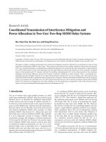
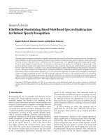
Figure 1: (a) Configuration of a dual-satellite 2 ×2 MIMO channel. Individual satellites S
1
and S
2
transmit either independent data streams
(MIMO spatial multiplexing system, Section 3) or the same signal over the multiple (ideally) independently fading paths (MIMO diversity
system, Section 4), (b) associated elevation angles.
of MIMO theory due to the intractability of the outage ca-
pacity distribution [2].
In the second part, a satellite 2
× 2MIMOdiversity sys-
tem employing receive antenna selection is examined, and
issues specifically related to cochannel interference (CCI) are
addressed from a propagation point of view. The term “di-
versity” refers to the transmission of the same signal over the
multiple (ideally) independently fading paths [1, 2]. Receive
antenna selection is a low-cost, low-complexity approach to
benefit from many of the advantages of MIMO technology
while, at the same time, bypassing the multiple RF chains
associated with multiple antennas at the receiver, which are
costly in terms of size, power, and hardware [21]. The inter-
ference analysis presented here is quite different from con-
ventional communication-oriented approaches followed in
standard MIMO theory [1]. Attention is paid to the CCI
problems arising on the forward link of such a 2
× 2MIMO
satellite system due to differential rain attenuation from an
adjacent satellite [22]. To deal with the statistical behaviour
of the signal-to-interference ratio (SIR) introduced by the
rainfall spatial inhomogeneity, the concept of unacceptable
inter ference probability
1
[23, 24] is employed here. An ana-
lytical prediction model concerning the interference mitiga-
tion achieved by the proposed satellite 2
×2MIMOdiversity
system is provided.
The rest of the paper is organized as follows. Section 2
presents the channel model adopted for MIMO satellite com-
munications at the Ku-band and above. Section 3 provides a
communication-based capacity analysis for a satellite 2
× 2
MIMO spatial multiplexing system. A propagation-oriented
1
Note that the concept of the “unacceptable interference probability
(UIP)” in this paper is exactly the same as that of the “acceptable interfer-
ence probability (AIP)” employed in [23, 24]. Their only difference con-
cerns their nomenclature.
analysis for the possible interference mitigation achieved by a
satellite 2
×2 MIMO diversity system with receive antenna se-
lection is presented in Section 4. Useful numerical results ob-
tained for both the above satellite MIMO applications con-
sidered are provided in Section 5. Section 6 concludes the
paper.
2. MIMO SATELLITE CHANNEL MODEL
Figure 1 depicts the configuration of a dual-satellite MIMO
communication channel at the Ku-band and above. The TS
is equipped with two colocated highly directive antennas and
communicates with two satellites, S
1
and S
2
, subtending an
angle Δ θ to the TS, large enough that the spatial correlation
due to rain along the relevant slant paths is as low as possible.
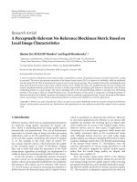
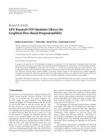
The normalized radiation pattern of each TS antenna, de-
noted by G
R
(·), is compatible with the ITU-R specifications
[25] and is shown in Figure 2.
2
The lengths of slant paths
S
i
-TS are denoted by d
i
(i = 1, 2) and the random variables
(RVs) associated with the respective rain induced attenua-
tions (in dB) are denoted by A
Ri
(i = 1, 2). In general, the
two slant paths S
i
-TShavedifferent elevation angles denoted
by φ
i
(i = 1, 2), respectively.
Assuming that clear LOS between the TS and each satel-
lite S
i
exists, that each TS antenna is at boresight with the
corresponding satellite S
i
(i = 1, 2) and that rain attenuation
is the major fading mechanism, the path gain for each S
i
-TS
link is modeled as
g
i
∝ G
R
0
◦
· d
−2
i
· 10
−A
R
i
/10
(i = 1, 2). (1)
2
Note that the analyses presented hereafter are quite general and, therefore,
may incorporate other TS antenna radiation patterns, as well.
4 EURASIP Journal on Wireless Communications and Networking
−100 −80 −60 −40 −200 20406080100
Off-axis angle (deg)
−40
−35
−30
−25
−20
−15
−10
−5
0
TS antenna normalized gain, G
R
(dB)
Figure 2: Normalized radiation pattern of each TS antenna com-
patible with ITU-R specifications [25].
Hence, the total path loss along each S
i
-TS link (in dB) is
A
i
= FSL
i
+ A
Ri
(i = 1, 2), (2)
where FSL
i
= 10log
10
(4πd
i
f/c)
2
is the free space loss along
each link, c the speed of light, and f the operating fre-
quency. Note that the fundamental assumptions concerning
the modeling of the rain attenuation RVs A
Ri
(i = 1, 2) are
the same as those analytically presented in [17]. The convec-
tive raincell model employing Crane’s assumptions is used
for the description of the vertical variation of the rainfall
structure [17]. Based on this assumption, if Δθ is sufficiently
large, the spatial correlation coefficient between the RVs A
Ri
is relatively low and, thus, an (ideally) decorrelated MIMO
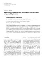
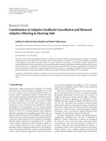
satellite channel is possible. To this end, an illustrative quan-
titative example is presented in Figure 3, which depicts the
spatial correlation coefficient due to rain ρ
12
versus Δθ for a
dual-satellite MIMO channel operating in Atlanta, GA, USA
at the Ka-band with satellite elevation angles φ
1
= 45
◦
and
φ
2
= 40
◦
.
Based on the above and, also, assuming frequency nonse-
lective fading, the resulting MIMO channel matrix H is given
by
H
=
h
11
h
12
h
21
h
22
=
⎡
⎢
⎢
⎣
√
g
1
exp
j2πd
1
f
c
0
0
√
g
2
exp
j2πd
2
f
c
⎤
⎥
⎥
⎦
.
(3)
The diagonal structure of H is due to the high directivity of
the TS antennas and the large value of Δθ.InMIMOter-
minology, channels with diagonal H matrix are known as
parallel MIMO channels. Further details about such chan-
nels can be found in [26]. Moreover , as opposed to s tandard
MIMO theory [1, 2], H is not normalized here (i.e., ordered
MIMO channel) due to the different slant path lengths d
i
0 20 40 60 80 100 120 140 160 180
Angular separation, Δθ (deg)
0.3
0.4
0.5
0.6
0.7
0.8
0.9
1
Spatial correlation coefficient due to rain, ρ
12
Figure 3: Spatial correlation coefficient due to rain ρ
12
versus an-
gular separation Δθ for a dual-satellite MIMO channel operating in
Atlanta, GA, at the Ka-band with satellite elevation angles φ
1
= 45
◦
and φ
2
= 40
◦
.
(i = 1, 2). Finally, the assumption of independent identically
distributed (i.i.d) elements of H, often made in conventional
terrestrial M IMO systems, cannot be made here, since there
is a relatively high spatial correlation due to rain.
3. SATELLITE MIMO SPATIAL MULTIPLEXING SYSTEM:
CAPACITY ANALYSIS
In this Section, the two satellites S
i
(i = 1, 2) depicted in
Figure 1 are assumed to transmit different and independent
data streams (i.e., spatial multiplexing is investigated). The
channel H is considered perfectly known to the TS receiver
(via training and tracking), while at the transmit side, both
satellites are assumed to have no channel knowledge. In the
absence of channel state information (CSI) at the transmit
side, equal power allocation to the two satellites is a reason-
able and rather practical choice, due to the distributed na-
ture of the system. Therefore, from the standard MIMO the-
ory, the following well-known formula for the capacity (in
bps/Hz) of MIMO channels is adopted [19, 20]:
C
= log
2
det
I
2
+
P
T
2N
0
HH
H
=
2
i=1
log
2
1+
P
T
2N
0
λ
i
,
(4)
where I
2
is the 2 × 2 identity matrix, P
T
the total average
power available at the transmit side,
3
N
0
the noise spectral
3
Note that P
T
is the sum transmit power of all transmitting satellites S
i
re-
gardless of their number. This means that in both the dual-satellite MIMO
case and the single satellite SISO case, the total available transmit power
is constant and equal to P
T
. This is ensured employing the normalization
factor “2” in (4),whichallowsforafaircomparisonbetweentherelevant
MIMO and SISO cases.
Konstantinos P. Liolis et al. 5
density at the TS receiver input, and λ
i
(i = 1,2) the positive
eigenvalues of the matrix HH
H
(the superscript
H
stands for
conjugate transposition).
Taking into account the channel modeling assumptions,
(4)iswrittenas
C =
2
i=1
log
2
1+0.5SNR
CSi
10
−A
Ri
/10
,(5)
where SNR
CSi
(i = 1, 2) are the nominal SNR values under
clear sky conditions. Based on the path gain model given in
(1), the SNR
CSi
values (in dB) are related through
SNR
CS1
− SNR
CS2
= 20 log
10
d
2
d
1
. (6)
Equation (5) provides an expression for the instantaneous
capacity of a deterministic 2
× 2 MIMO channel H.How-
ever, since the rainfall introduces slow fading and stochastic
behaviour over the channel H, the appropriate statistic mea-
sure to characterize the resulting fading channel is the outage
capacity defined by [1]
P
C ≤ C
out,q
=
q,(7)
where C
out,q
is the information rate guaranteed for (1−
q)100% of the channel realizations.
Consider the RV transformation
u
i
=
ln
A
Ri
− ln
A
m
Ri
S
a
Ri
(i = 1, 2) (8)
which relates the lognormal rain attenuation RVs A
Ri
(i =
1, 2) to the normalized normal RVs u
i
(i = 1, 2). Substituting
(5) into (7) and after some straightforward algebra, the fol-
lowing analytical closed form expression for the outage ca-
pacity is obtained:
P
C ≤ C
out,q
=
1
2
+∞
u
A
du
1
f
U
1
u
1
erfc
u
B
− ρ
n12
u
1
2
1 − ρ
2
n12
=
q,
(9)
where erfc(
·) is the complementary error function, f
U
1
(u
1
)
the probability density function (pdf) of the normal distri-
bution, ρ
n12
the logarithmic correlation coefficient between
the normal RVs u
i
(i = 1, 2) [17]andu
A
, u
B
are analytically
given by
u
A
=
ln
10 log
10
0.5SNR
CS2
− 10 log
10
2
C
out,q
− 1
−
ln
A
m
R2
S
a
R2
,
(10)
u
B
=
ln
10 log
10
0.5SNR
CS1
+10log
10
1+0.5SNR
CS2
10
−A
m
R2
exp(u
1
S
a
R2
)/10
−
10 log
10
2
C
out,q
−1−0.5SNR
CS2
10
−A
m
R2
exp(u
1
S
a
R2
)/10
−
ln
A
m
R1
S
a
R1
.
(11)
The quantities A
m
Ri
, S
a
Ri
(i = 1, 2), encountered in (8)–(11),
are the statistical par a meters of the lognormal RVs A
Ri
(i =
1, 2) given by [17]
S
2
a
Ri
= ln
1+
H
i
L
2
Di
exp
b
2
S
2
r
− 1
(i = 1, 2),
A
m
Ri
= aR
b
m
L
Di
exp
b
2
S
2
r
− S
2
a
Ri
2
(i = 1, 2),
(12)
where L
Di
(i = 1, 2) are the projections of the effective path
lengths L
i
(i = 1, 2) [17] on the earth surface, H
i
(i = 1, 2) are
spatial parameters related to each path of length L
Di
(i = 1, 2)
which may be found in [17], and a, b are constants depend-
ing on the operating frequency f , the polarization tilt angle,
the temperature, and the rainfall characteristics over the ser-
viced area. R
m
, S
r
are the lognormal statistical parameters of
the rainfall rate R (in mm/hr). A reliable database of rainfall
statistics for any geographical location on earth is provided
by ITU-R in [18] and is used throughout the present work as
an input to the simulations performed in order to determine
the values of R
m
, S
r
.
4. SATELLITE MIMO DIVERSITY SYSTEM
WITH RECEIVE ANTENNA SELECTION:
INTERFERENCE ANALYSIS
In this section, the two satellites S
i
(i = 1, 2) depicted in
Figure 1 are assumed to transmit the same signal over the
(ideally) independently fading paths S
i
-TS (i = 1, 2) (i.e., di-
versity is investigated). To alleviate the high cost and com-
plexity associated with multiple RF chains, the dual-antenna
TS receiver is equipped with only one RF chain and performs
antenna selection, that is, the 2
× 2 MIMO satellite system
assumed employs receive selection diversity [21]. Therefore,
the TS receiver detects the signal related to the path with the
highest SNR. Under the constraint of only one RF chain at
the receiver, in order to know all SNRs simultaneously for
optimal selection, a training signal in a preamble to the trans-
mitted data is assumed. During this preamble, the TS receiver
scans the two antennas, finds that one with the highest SNR,
and selects it for reception of the next data burst. Thus, only
a few more training bits are required instead of additional RF
chains.
Particular emphasis is put on possible interference mit-
igation offered by the proposed satellite 2
× 2 MIMO di-
versity system. In this regard, a propagation-based analy-
sisisperformedwhichisquitedifferent from conventional
communication-oriented approaches followed in standard
MIMO theory [1]. Specifically, the effect of rainfall on the
interference analysis is taken into account and the differential
rain attenuation related to an adjacent satellite is considered
as the dominant cause of the SIR degradation [22]. Such an
interference problem is further aggravated due to the spa-
tial inhomogeneity of the rainfall medium. It constitutes a
typical interference scenario, especially over congested urban
areas, where the increased demand for link capacity and ra-
dio coverage imposes the coexistence of many satellite radio
links over the same geographical and spectral area. In the fol-
lowing, an analytical prediction model is presented, which
6 EURASIP Journal on Wireless Communications and Networking
S
1
S
3
S
2
d
1
, A
R1
d
3
, A
R3
d
2
, A
R2
Δθ
Δψ
TS
(a)
T
o
S
1
T
o
S
3
T
o
S
2
ϕ
3
ϕ
2
ϕ
1
TS
(b)
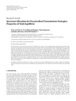
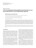
Figure 4: (a) Configuration of the satellite 2 × 2 MIMO diversity system assumed and the interference scenario on its forward link, (b)
associated elevation angles.
quantifies the adjacent satellite CCI mitigation achieved by
the proposed 2
× 2 MIMO system with respect to the corre-
sponding SISO one.
Figure 4 depicts the configuration of the assumed inter-
ference scenario on the forward link of a satellite 2
×2MIMO
diversity system opera ting at the Ku-band and above and
employing receive antenna selection. The satellites S
1
and
S
2
constitute the dual-satellite transmit part of the MIMO
system also depicted in Figure 1. Another cochannel satellite
(denoted by S
3
), which may belong to either the same or to
another satellite network, is close in orbit to S
1
. Thus, CCI
problems may arise on the forward link of the 2
× 2MIMO
satellite system. S
1
and S
3
subtend an angle Δψ to TS. The
length of the slant path S
3
-TSisdenotedbyd
3
, while its ele-
vation angle is φ
3
. The RV associated with the rain induced
attenuation along the interfering path S
3
-TS (in dB) is de-
noted by A
R3
.
Due to selection diversity at the TS receiver, the antenna
with the maximum SNR is selected. In mathematical terms,
the same statement is expressed as
SNR
out
= max
SNR
1
,SNR
2
⇐⇒
A
out
= min
A
1
, A
2
,
(13)
where SNR
i
= SNR
CSi
− A
Ri
(i = 1, 2) is the SNR at each TS
antenna under rain fades and A
i
(i = 1, 2) the total path loss
along each S
i
-TS link (i = 1, 2). SNR
out
corresponds to A
out
which determines the output of the select ion combiner at ev-
ery instant. The proposed scheme requires only the knowl-
edge of the wanted signals’ channels at the receiver, whereas
knowledge of the interferer’s channel is not necessary. More-
over, no CSI is required at the transmit side. If M
d
denotes
the diversity system margin associated with the system avail-
ability p
avail
(see the appendix), the satellite MIMO diversity
system is considered available when the probabilistic event
Ω
=
A
out
<M
d
(14)
is true. Assuming that
Ω
i
=
A
i
<M
d
, A
i
<A
j
(i, j) = (1, 2), (2, 1)
(15)
denotes the event that “the TS is serviced by the correspond-
ing satellite S
i
(i = 1,2),” it becomes clear that, due to selec-
tion diversity,
Ω
= Ω
1
∪ Ω
2
,
Ω
1
∩ Ω
2
=∅.
(16)
Therefore, the probability that the system is available (see the
appendix) can be expressed as
P(Ω)
= P
Ω
1
+ P
Ω
2
. (17)
While the satellite 2
× 2 MIMO diversity system is avail-
able (i.e., when either Ω
1
or Ω
2
are true), it might suffer from
CCI originating from the adjacent satellite S
3
. If SIR
d
and r
d
denote the SIR and the minimum acceptable SIR threshold
of the MIMO diversity system, respectively (both measured
at the output of the TS selection combiner), the probability
of the event that “the system is interfered while being avail-
able” can be mathematically expressed based on the above
considerations as
UIP
d
= P
SIR
d
<r
d
, Ω
= P
SIR
d1
<r
d
, Ω
1
+ P
SIR
d2
<r
d
, Ω
2
= P
1
+ P
2
,
(18)
where UIP
d
is the so-called unacceptable interference proba-
bility (UIP) [23, 24], and the quantities SIR
di
(i = 1, 2) are
expressed (in dB) as
SIR
d
= SIR
di
= SIR
CSi
− A
Ri
+ A
R3
(i = 1, 2). (19)
In (19), SIR
CSi
(i = 1, 2) is the nominal SIR value under
clear sky conditions. In propagation terminology, A
Ri
− A
R3
Konstantinos P. Liolis et al. 7
(i = 1,2) is known as the differential rain attenuation (DRA)
[22]. Based on (19), when DRA becomes sufficiently large
due to the spatial inhomogeneity of the rainfall medium, se-
vere CCI problems may arise aggravating the SIR
d
distribu-
tion on the forward link of the proposed satellite 2
×2MIMO
diversity system. To this end, UIP
d
is proposed as an efficient
metric to deal with the statistical behaviour of the SIR
d
and,
together with r
d
, they constitute a pair of design specifica-
tions concerning interference. Every user must comply with
these specifications, given the QoS specified by the event Ω
related to the system availability (see the appendix).
The quantities SIR
CSi
(i = 1,2) encountered in ( 19)are
given by
SIR
CSi
= SIR
∗
i
− G
R
θ
i
(i = 1, 2), (20)
where θ
i
(i = 1, 2) are the off-axis angles formed by the in-
terfering link S
3
-TS and the wanted links S
i
-TS (i = 1, 2) in
the radiation pattern of the TS antennas. From Figure 4,it
follows that θ
1
= Δψ and θ
2
= Δθ − Δψ. Also, in (20), SIR
∗
i
(i = 1, 2) are the relevant SIR values of the interfered links
S
i
-TS (i = 1, 2) when θ
i
= 1
◦
, and correspond to the nominal
CCI levels. Based on the channel model assumed, their inter-
relationship is defined through (6) by simply substituting the
SNR
CSi
by SIR
∗
i
.
Extending the transformation given in (8) to include also
the interfering link S
3
-TS (i.e., for i = 1, 2,3) and making the
channel modeling assumptions, the probabilities P
i
(i = 1, 2)
encountered in (18) after some straightforward algebra are
evaluated, that is,
P
i
=
u
Di
u
Ci
du
1
+∞
u
1
du
2
f
U
1
U
2
u
1
, u
2
×
1 −
1
2
erfc
u
Ei
− μ
3/1,2
√
2σ
3/1,2
(i = 1, 2),
(21)
where f
U
1
U
2
(u
1
, u
2
) is the pdf of the two-dimensional joint
normal distribution.
For i
= 1, 2, the rest of the parameters encountered in
(21)are
u
Ci
=
ln
x
di
− ln
A
m
Ri
S
a
Ri
,
x
di
=
⎧
⎪
⎪
⎨
⎪
⎪
⎩
0, r
d
> SIR
CSi
,
SIR
CSi
−r
d
cos φ
i
, SIR
CSi
+FSL
i
−M
d
<r
d
≤SIR
CSi
,
M
d
− FSL
i
cos φ
i
, r
d
≤ SIR
CSi
+FSL
i
− M
d
,
u
Di
=
ln
M
d
− FSL
i
cos φ
i
−
ln
A
m
Ri
S
a
Ri
,
u
Ei
=
ln
exp
u
i
S
a
Ri
A
m
Ri
cos φ
i
− SIR
CSi
+ r
d
cos φ
3
−
ln
A
m
R3
S
a
R3
.
(22)
A
m
Ri
, S
a
Ri
(i = 1, 2,3) are analytically given in (12). Fur-
thermore, μ
3/1,2
and σ
3/1,2
are the statistical parameters of
the conditional distribution of the normal RV u
3
given
the other two normal RVs u
1
, u
2
and can be expressed in
terms of the logarithmic correlation coefficients ρ
nij
((i, j) =
(1, 2), (1, 3), (2, 3)) as [17, 27]
μ
3/1,2
=
ρ
n13
− ρ
n12
ρ
n23
1 − ρ
2
n12
u
1
+
ρ
n23
− ρ
n12
ρ
n13
1 − ρ
2
n12
u
2
,
σ
2
3/1,2
=
1 − ρ
2
n12
− ρ
2
n13
− ρ
2
n23
+2ρ
n12
ρ
n13
ρ
n23
1 − ρ
2
n12
.
(23)
5. NUMERICAL RESULTS AND DISCUSSION
The previous analyses have been applied for the prediction
of possible capacity improvement and interference mitiga-
tion achieved by the proposed satellite 2
× 2MIMOspa-
tial multiplexing and diversity systems, respectively, and for
comparison to the relevant SISO cases. To this end, the base-
line configuration scenario considers a TS located in At-
lanta, GA, and communicating with geostationary satellites
S
1
(φ
1
= 45
◦
)andS
2
(φ
2
= 40
◦
). The angular separation as-
sumed is Δθ
=40
◦
, which results in a spatial correlation coef-
ficient of rain attenuation ρ
12
= 0.6 (see Figure 3). Moreover,
regarding the interference scenario, an adjacent geostation-
ar y satellite S
3
(φ
3
= 45
◦
), separated from S
1
by Δψ=10
◦
,is
considered to cause CCI problems on the forward link of the
satellite 2
× 2 MIMO diversity system.
First, the validity of the proposed analytical model in (9),
predicting the outage capacity achieved by a satellite 2
× 2
MIMO spatial multiplexing system, is numerically verified.
The effect of various geometrical and operational system pa-
rameters on the outage capacity distribution is also exam-
ined.
Figure 5 shows the dependence of the 1% outage capac-
ity of the assumed 2
×2 MIMO satellite system on the SNR.
4
The baseline configuration scenario is adopted, whereas the
operating frequency band assumed is Ka (i.e., f
= 20 GHz).
For the sake of comparison, the capacity of the relevant SISO
system is also plotted. Together with the analytical results
obtained from the analytical closed form expression in (9),
Monte Carlo simulation results are also plotted for verifica-
tion. The agreement observed between the analytical and the
simulation results is very good over the whole SNR range.
As can be seen, the difference between the relevant MIMO
and SISO curves diminishes at very low SNR levels while
it becomes significant as the SNR increases. As an illustra-
tion, for SNR
= 10dB, the spectral efficiency achieved by
the MIMO system is 4.84 bps/Hz, whereas the one achieved
by the SISO system is 3.23 bps/Hz. This constitutes, approx-
imately, a 50% increase in user data rate obtained by MIMO
spatial multiplexing. For SNR
= 20 dB, the respective per-
formance figures obtained are 10.95 bps/Hz and 6.41 bps/Hz
corresponding to, approximately, a 71% increase in user data
4
Note that the clear sky SNR of strong eigenmode, SNR
CS1
,hasbeenpar-
ticularly considered. However, due to the enormous slant path lengths as-
sociated, the resulting difference between SNR
CSi
(i = 1, 2) is minimum
see (6) and, therefore, any of the two SNR
CSi
can be used as x-coordinates.
8 EURASIP Journal on Wireless Communications and Networking
0 5 10 15 20 25 30
SNR (dB)
0
2
4
6
8
10
12
14
16
18
1% outage capacity (bps/Hz)
Analytical expression (9)
Monte Carlo simulation
2
× 2MIMO
SISO
Figure 5: 1% outage capacity versus SNR for a satellite 2×2MIMO
spatial multiplexing system. Relevant SISO case is also plotted for
comparison. Verification of analytical closed form expression in (9)
through Monte Carlo simulation.
0 5 10 15 20 25 30
SNR (dB)
0
2
4
6
8
10
12
14
16
18
Outage capacity achieved by
2
× 2 MIMO system (bps/Hz)
q = 1%, Δθ = 40
◦
, Ka-band, Atlanta
q
= 0.1%, Δθ = 40
◦
, Ka-band, Atlanta
q
= 1%, Δθ = 40
◦
, Ku-band, Atlanta
q
= 1%, Δθ = 40
◦
, Ka-band, Singapore
q
= 1%, Δθ = 60
◦
, Ka-band, Atlanta
Figure 6: Outage capacity versus SNR for a satellite 2 × 2 MIMO
spatial multiplexing system. Effect of capacity outage probability q,
angular separation Δθ, operating frequency f , and climatic condi-
tions over the serviced area.
rate. Therefore, the capacity gain obtained by the proposed
satellite 2
× 2 MIMO spatial multiplexing system over the
SISO system turns out to be significant for n o additional
transmit power or bandwidth expenditure.
Figure 6 shows the dependence of the outage capacity
achieved by a satellite 2
× 2 MIMO spatial multiplexing sys-
tem on the SNR, the angular separation Δθ, the operating
frequency f , the capacity outage probability q, and the cli-
matic conditions over the serviced area. All the results pre-
sented here have been obtained employing (9). The baseline
configuration scenario is adopted. The rest of the relevant pa-
rameters assumed as well as the dev iations from the baseline
scenario are indicated on Figure 6. As can be seen, as either q
decreases or f increases or as the rain conditions over the ser-
viced area become heavier, the rain fading becomes more se-
vere and, therefore, the outage capacity achieved by the 2
×2
MIMO satellite system decreases. Moreover, as the angular
separation Δθ increases (from 40
◦
to 60
◦
), the spatial corre-
lation coefficient due to rainfall medium ρ
12
decreases cor-
respondingly (from 0.6 to 0.5, see Figure 3), and the outage
capacity achieved increases.
In the following, the proposed analytical model in (21)
predicting the interference mitigation achieved by a satellite
2
× 2 MIMO diversity system with receive antenna selection
is numerically verified. The effect of various geometrical and
operational system parameters on the forward link SIR dis-
tribution is also examined.
Figure 7 shows the dependence of the UIP of the assumed
2
× 2 MIMO satellite system on the SIR, the system avail-
ability p
avail
, and the operating frequency band. Particularly,
two different values of system availability, p
avail
= 99.9%
and 99.99%, and two different operating frequencies, f
=
12 GHz and 20 GHz, are assumed. For the sake of compar-
ison, the UIP of the relevant SISO systems is also plotted.
The baseline configuration scenario is adopted. The nomi-
nal CCI level assumed is SIR
∗
1
= 20 dB, whereas the rest of
the parameters encountered in the interference analysis are
indicated on Figure 7. It is obvious that, due to rain, an SIR
degradation is observed for the same UIP level, which be-
comesmoresevereaseitherp
avail
or f increases. This fur-
ther indicates that satellite systems operating at higher avail-
abilities or at higher-frequency bands are more sensitive to
interference. The SIR improvement achieved by the satellite
2
× 2 MIMO diversity system over the SISO one is signifi-
cant, especially for high p
avail
and high f . As an illustration,
for UIP
= 0.001%, the interference mitigation obtained is
0.67 dB at the Ka-band and for a 99.9% availability, 1.60 dB
at the Ku-band and for a 99.99% availability, and 3.52 dB at
the Ka-band and for a 99.99% availability.
Figure 8 quantifies the SIR improvement achieved by a
satellite 2
× 2 MIMO diversity system employing receive
antenna selection with respect to the relevant SISO one.
Specifically, the difference (in dB) between the respective
SIR thresholds achieved at the TS receiver input for UIP
=
0.001% is plotted versus the angular separation Δθ.Two
areas with different climatic conditions are considered, At-
lanta, GA, and Athens, Greece. The operating frequency, sys-
tem availability, and nominal CCI level assumed are 20 GHz,
99.99%, and SIR
∗
1
= 20 dB, respectively, while the rest of
the parameters are the same as those of the baseline con-
figuration scenario. As Δθ increases, the interference miti-
gation level achieved becomes higher. Moreover, it can easily
be observed that the SIR improvement obtained in Atlanta,
Konstantinos P. Liolis et al. 9
2 4 6 8 10 12 14 16 18 20
SIR (dB)
10
−6
10
−5
10
−4
10
−3
10
−2
10
−1
10
0
Unacceptable interference probability (UIP)
SISO
2
× 2MIMO
Ka-band,
p
avail
= 99.9%
Ku-band,
p
avail
= 99.99%
Ka-band,
p
avail
= 99.99%
Figure 7: UIP versus SIR for a satellite 2 × 2 MIMO diversity sys-
tem employing receive antenna selection. Relevant SISO case is also
plotted for comparison. Effect of system availability p
avail
, operating
frequency f , and rain climatic conditions over the serviced area.
20 30 40 50 60
70
80 90
Angular separation, Δθ (deg)
0
0.5
1
1.5
2
2.5
SIR improvement achieved through
MIMO diversity (dB)
Atlanta, GA
Athens, GR
Figure 8: SIR improvement achieved by a satellite 2 × 2MIMOdi-
versity system with receive antenna selection over the relevant SISO
system versus angular separation Δθ.Effect of rain climatic condi-
tions over the serviced area.
GA, is much higher than that in Athens, Greece, due to the
corresponding heavier rain conditions.
For various obvious reasons, there is a tendency to place
satellites in orbit close to each other. Due to the increased
CCI, adjacent satellite networks cannot usually operate un-
der certain SIR specifications. The proposed MIMO diversity
system may overcome this problem by adequately increasing
SIR in the presence of adjacent CCI. To demonstrate this, a
satellite 2
× 2 MIMO diversity system together with its rele-
vant SISO case are considered in Figure 9. The input parame-
7 9 11 13 15 17 19 20
SIR (dB)
10
−6
10
−5
10
−4
10
−3
10
−2
10
−1
10
0
Unacceptable interference probability (UIP)
SISO
2
× 2MIMO
Δψ
= 4
◦
Δψ = 5
◦
Figure 9: UIP versus SIR for a satellite 2 × 2 MIMO diversity sys-
tem employing receive antenna selection. Relevant SISO case is also
plotted for comparison. Effect of angular separation ΔΨ.
ters assumed are the same as those in the baseline configura-
tion scenario, with the exception of a different angular sepa-
ration Δψ, that is, Δψ
= 5
◦
is now assumed. Operation of the
system at the Ka-band and for a 99.99% availability is con-
sidered. To obtain the necessary QoS for UIP
= 0.001%, sup-
pose that an SIR threshold of 10 dB must be overcome. In the
SISO case, when the angular separation between the wanted
satellite S
1
and the adjacent interfering one S
3
is Δψ = 5
◦
,
an SIR level of 11.2 dB is obtained for UIP
= 0.001%, thus
satisfying the QoS requirement. If the interfering satellite S
3
is closer in orbit to S
1
, so that their angular separation is re-
duced to Δ ψ
= 4
◦
, the SIR level in the SISO case falls down
to 9.8 dB, thus failing to satisfy the QoS requirement. Em-
ploying the proposed 2
× 2 MIMO satellite system, the SIR
achieved when Δψ
= 4
◦
is 11.32 dB, thus remaining above
the QoS threshold. This is another advantage of the proposed
satellite MIMO diversity system, allowing the closer installa-
tion of satellites in orbit.
6. CONCLUSIONS
In this paper, the applicability of MIMO technology to satel-
lite communication systems operating at the Ku-band and
above is investigated. Emphasis is put on satellite diversity as
a potential candidate to form a MIMO matrix channel in the
satellite environment. The relevant propagation phenomena
at the frequencies of interest have been considered through
an appropriate physical channel model, which takes into ac-
count clear LOS operation, hig h antenna directivity at the TS
receiver, the effect of rain fading , and the slant path lengths
difference. Also, as it may accept physical inputs from the
ITU-R rainmaps, it is flexible and can be applied on a global
scale.
10 EURASIP Journal on Wireless Communications and Networking
Useful analytical results are presented for two different
applications of MIMO technology:
(i) capacity improvement in a satellite 2
×2MIMOspatial
multiplexing system,
(ii) interference mitigation in a satellite 2
× 2 MIMO di-
versity system with receive antenna selection.
In the first application, significant capacity gains of the
MIMO system over the relevant SISO one are demonstrated,
especially for moderate and high SNR levels. The practical
case when no CSI is available at the transmitters of the two
individual satellites is considered. A useful closed form ex-
pression for the outage capacity achieved by 2
× 2MIMO
satellite systems is provided and successfully verified through
Monte Carlo simulations. Such an expression is extremely
hard to obtain even in the well-established field of MIMO
theory, is applicable over a large SNR range, and can incorpo-
rate the effect of various geometrical and operational system
parameters on the outage capacity distribution.
In the second application, the receive antenna selection
scheme employed in the satellite MIMO system assumed is
considered to counteract CCI problems over its forward link.
SIR gain of several dB is demonstrated in the numerical re-
sults. An analytical propagation model for the calculation of
the interference mitigation achieved is presented, which is
flexible and can incorporate the influence of various geomet-
rical and operational system parameters on the SIR distribu-
tion.
APPENDIX
CALCULATION OF SATELLITE 2
× 2 MIMO
DIVERSITY SYSTEM MARGIN M
d
Every u ser in the assumed satellite 2 ×2 MIMO diversity sys-
tem employing receive antenna selection must comply with a
certain availability percentage p
avail
related to a diversity sys-
tem margin M
d
:
p
avail
· 100% = P(Ω) = P
A
out
<M
d
=
P
min
A
1
, A
2
<M
d
=
1 − P
A
1
>M
d
, A
2
>M
d
= 1 − P
A
R1
>M
d
− FSL
1
, A
R2
>M
d
− FSL
2
.
(.1)
Considering the transformation given in (8), relating the log-
normal rain attenuation RVs A
Ri
(i = 1, 2) to the normalized
normal RVs u
i
(i = 1, 2), and the channel modeling assump-
tions, p
avail
is expressed as
p
avail
· 100% = 1 −
+∞
u
F1
du
1
+∞
u
F2
du
2
f
U
1
U
2
u
1
, u
2
,(.2)
where
u
Fi
=
ln
M
d
− FSL
i
cos φ
i
−
ln
A
m
Ri
S
a
Ri
(i = 1, 2).
(.3)
After straightforward algebra, (.2) yields
p
avail
· 100%
= 1 − 0.5
+∞
u
F1
du
1
f
U
1
u
1
erfc
u
F2
− ρ
n12
u
1
2
1 − ρ
2
n12
.
(.4)
ACKNOWLEDGMENTS
The authors are indebted to the three anonymous review-
ers whose constructive comments helpe d to significantly im-
prove the initial version of this paper. Moreover, the first au-
thor would like to thank Professor Bhaskar D. Rao from Uni-
versity of California, San Diego, USA, for the fruitful discus-
sions they had on the first part of this work.
REFERENCES
[1]A.J.Paulraj,D.A.Gore,R.U.Nabar,andH.B
¨
olcskei, “An
overview of MIMO communications—a key to gigabit wire-
less,” Proceedings of the IEEE, vol. 92, no. 2, pp. 198–218, 2004.
[2] D. Gesbert, M. Shafi, D S. Shiu, P. J. Smith, and A. Naguib,
“From theory to practice: an overview of MIMO space-time
coded wireless systems,” IEEE Journal on Selected Areas in
Communications, vol. 21, no. 3, pp. 281–302, 2003.
[3] A. D. Panagopoulos, P D. M. Arapoglou, and P. G. Cottis,
“Satellite communications at Ku, Ka, and V bands: propaga-
tion impairments and mitigation techniques,” IEEE Commu-
nications Surveys and Tutorials, vol. 6, no. 3, pp. 2–14, 2004.
[4] K. P. Liolis, A. D. Panagopoulos, and P. G. Cottis, “Outage ca-
pacity statistics of MIMO satellite networks operating at Ka
band and above,” in Proceedings of the 12th Ka and Broadband
Communications Conference, Naples, Italy, September 2006.
[5] F. Yamashita, K. Kobayashi, M. Ueba, and M. Umehira,
“Broadband multiple satellite MIMO system,” in Proceedings
of the 62nd IEEE Vehicular Technology Conference (VTC ’05),
pp. 2632–2636, Dallas, Tex, USA, September 2005.
[6] P. R. King and S. Stavrou, “Land mobile-satellite MIMO ca-
pacity predictions,” Electronics Letters, vol. 41, no. 13, pp. 749–
751, 2005.
[7] T. Hult and A. Mohammed, “MIMO antenna applications
for LEO satellite communications,” in Proceedings of the 3rd
ESA International Workshop of the European COST 280 Action,
Prague, Czech Republic, June 2005.
[8] C. Martin, A. Geurtz, and B. Ottersten, “Spectrally efficient
mobile satellite real-time broadcast with transmit diversity,”
in Proceedings of the 60th IEEE Vehicular Technology Confer-
ence (VTC ’04), vol. 6, pp. 4079–4083, Los Angeles, Calif, U SA,
September 2004.
[9] C. Faller, B H. Juang, P. Kroon, H L. Lou, S. A. Ramprashad,
and C E. W. Sundberg, “Technical advances in digital audio
radio broadcasting,” Proceedings of the IEEE,vol.90,no.8,pp.
1303–1333, 2002.
[10] J. Mietzner and P. A. Hoeher, “Distributed space-time codes
for cooperative wireless networks in the presence of different
propagation delays and path losses,” in Proceedings of Sensor
Array and Multichannel Signal Processing Workshop (SAM ’04),
pp. 264–268, Barcelona, Spain, July 2004.
[11] B. N. Getu and J. B. Andersen, “The MIMO cube—a compact
MIMO antenna,” IEEE Transactions on Wireless Communica-
tions, vol. 4, no. 3, pp. 1136–1141, 2005.
Konstantinos P. Liolis et al. 11
[12] I. Frigyes and P. Horv
´
ath, “Polarization-time coding in satel-
lite links,” IEEE Satellite and Space Communications Newsletter,
vol. 15, no. 2, pp. 6–8, 2005.
[13] P. Horv
´
ath and I. Frig yes, “SAT02-6: application of the
3D polar ization concept in satellite MIMO systems,” in
Proceedings of IEEE Global Telecommunications Conference
(GLOBECOM ’06), pp. 1–5, San Francisco, Calif, USA,
November 2006.
[14] P. R. King and S. Stavrou, “Capacity improvement for a land
mobile single satellite MIMO system,” Antennas and Wireless
Propagation Letters, vol. 5, no. 1, pp. 98–100, 2006.
[15] M. Sellathurai, P. Guinand, and J. Lodge, “Space-time cod-
ing in mobile satellite communications using dual-polarized
channels,” IEEE Transactions on Vehicular Technolog y, vol. 55,
no. 1, pp. 188–199, 2006.
[16] G. Taricco, E. Viterbo, and E. Biglier, “MIMO transmission for
mobile satellite communication systems: a review,” in Proceed-
ings of the 8th International Workshop on Signal Processing for
Space Communications (SPSC ’03),Catania,Italy,September
2003.
[17] A. D. Panagopoulos and J. D. Kanellopoulos, “Prediction of
triple-orbital diversity performance in Earth-space commu-
nication,” International Journal of Satellite Communications,
vol. 20, no. 3, pp. 187–200, 2002.
[18] ITU-R Recommendation P.837-4, “Characteristics of Precipi-
tation for Propagation Modeling,” Geneva, Switzerland, 2003.
[19] G. J. Foschini and M. J. Gans, “On limits of wireless commu-
nications in a fading environment when using multiple an-
tennas,” Wireless Personal Communications,vol.6,no.3,pp.
311–335, 1998.
[20] I. E. Telatar, “Capacity of multi-antenna Gaussian channels,”
European Transactions on Telecommunications, vol. 10, no. 6,
pp. 585–595, 1999.
[21] S. Sanayei and A. Nosratinia, “Antenna selection in MIMO sys-
tems,” IEEE Communications Magazine, vol. 42, no. 10, pp. 68–
73, 2004.
[22] J. D. Kanellopoulos, S. Ventouras, and C. N. Vazouras, “A re-
vised model for the prediction of differential rain attenua-
tion on adjacent Earth-space propagation paths,” Radio Sci-
ence, vol. 28, no. 6 part 2, pp. 1071–1086, 1993.
[23]P D.M.Arapoglou,A.D.Panagopoulos,J.D.Kanellopou-
los, and P. G. Cottis, “Intercell radio interference studies in
CDMA-based LMDS networks,” IEEE Transactions on Anten-
nas and Propagation, vol. 53, no. 8, pp. 2471–2479, 2005.
[24] A. D. Panagopoulos, P D. M. Arapoglou, J. D. Kanellopoulos,
and P. G. Cottis, “Intercell radio interference studies in broad-
band wireless access networks,” IEEE Transactions on Vehicular
Technology, vol. 56, no. 1, pp. 3–12, 2007.
[25] ITU-R Recommendation S.580-6, “Radiation Diagrams for
Use as Design Objectives for Antennas of Earth Stations Op-
erating with Geostationary Satellites,” Geneva, Switzerland,
2004.
[26] P. Horv
´
ath and I. Frigyes, “Application of the MIMO concept
in millimeter-wave broadband wireless access networks,” In-
ternational Journal of Wireless Information Networks, vol. 11,
no. 4, pp. 217–225, 2004.
[27] A. Papoulis and S. U. Pillai, Probability, Random Variables and
Stochastic Processes, McGraw-Hill, Englewood Cliffs, NJ, USA,
4th edition, 2002.