Báo cáo hóa học: " Research Article Distributed Temporal Multiple Description Coding for Robust Video Transmission" docx
Bạn đang xem bản rút gọn của tài liệu. Xem và tải ngay bản đầy đủ của tài liệu tại đây (1.32 MB, 13 trang )
Hindawi Publishing Corporation
EURASIP Journal on Wireless Communications and Networking
Volume 2008, Article ID 183536, 13 pages
doi:10.1155/2008/183536
Research Article
Distributed Temporal Multiple Description Coding for
Robust Video Transmission
Olivier Crave,
1, 2
Christine Guillemot,
1
B
´
eatrice Pesquet-Popescu,
2
and Christophe Tillier
2
1
Institut de Recherche en Informatique et Syst
`
emes Al
´
eatoires, Institut National de Recherche en Informatique
et en Automatique, 35042 Rennes Cedex, France
2
Groupe des
´
Ecoles des T
´
el
´
ecommunications, D
´
eparteme nt TSI Signal-Images,
´
Ecole Nationale Sup
´
erieure des
T
´
el
´
ecommunications, 46 rue Barrault, 75634 Paris C
´
edex 13, France
Correspondence should be addressed to Olivier Crave,
Received 22 March 2007; Accepted 6 June 2007
Recommended by Peter Schelkens
The problem of multimedia communications over best-effort networks is addressed here with multiple descr iption coding (MDC)
in a distributed framework. In this paper, we first compare four video MDC schemes based on different time splitting patterns
and temporal two- or three-band motion-compensated temporal filtering (MCTF). Then, the latter schemes are extended with
systematic lossy description coding where the original sequence is separated into two subsequences, one being coded as in the
latter schemes, and the other being coded with a Wyner-Ziv (WZ) encoder. This amounts to having a systematic lossy Wyner-Ziv
coding of every other frame of each description. This error control approach can be used as an alternative to automatic repeat
request (ARQ) or forward error correction (FEC), that is, the additional bitstream can be systematically sent to the decoder or can
be requested, as in ARQ. When used as an FEC mechanism, the amount of redundancy is mostly controlled by the quantization of
the Wyner-Ziv data. In this context, this approach leads to satisfactory rate-distortion performance at the side decoders, however
it suffers from high redundancy which penalizes the central description. To cope with this problem, the approach is then extended
to the use of MCTF for the Wyner-Ziv frames, in which case only the low-frequency subbands are WZ-coded and sent in the
descriptions.
Copyright © 2008 Olivier Crave et al. This is an open access article distributed under the Creative Commons Attribution License,
which permits unrestricted use, distribution, and reproduction in any medium, provided the original work is properly cited.
1. INTRODUCTION
Due to the real-time nature of envisioned data streams,
multimedia delivery usually makes use of transport proto-
cols, that is, User Datagram Protocol (UDP) and/or Real-
time Transport Protocol (RTP) which do not include con-
trol mechanisms which would guarantee a level of Quality of
Service (QoS). The data transmitted may hence suffer from
losses due to network failure or congestion. Traditional ap-
proaches to fight against losses mostly rely on the use of
Automatic repeat request (ARQ) techniques and/or forward
error correction (FEC). ARQ offers to the application level
a guaranteed data transport service. However, the delay in-
duced by the retransmission of lost packets may not be ap-
propriate for multimedia applications with delay constraints.
FEC consists in sending redundant information along with
the original information. The advantage of FEC is that there
is no need for a feedback channel. However, if the channel
degrades rapidly due to fading or shadowing, or if the es-
timated probability of transmission errors is lower than the
actual value, then the FEC parity information is not sufficient
for error correction. Hence, the video quality may degrade
rapidly, leading to the undesirable cliff effect.
Multiple description coding (MDC) has been recently
considered for robust video transmission over lossy channels.
Several correlated coded representations of the signal are cre-
ated and transmitted on multiple channels. The problem ad-
dressed is how to achieve the best average rate-distortion
(RD) performance when all the channels work, subject to
constraints on the average distortion when only a subset of
channels is correctly received. Practical systems for gener-
ating descriptions that would best approach these theoreti-
cal bounds have also been designed considering the different
components of compression system, as the spatio-temporal
transform or the quantization. The reader is referred to [1]
for a comprehensive general review of MDC.
2 EURASIP Journal on Wireless Communications and Networking
Wyner-Ziv (WZ) coding can also be used as a forward er-
ror correction (FEC) mechanism. This idea has been initially
suggested in [2] for analog transmission enhanced with WZ-
encoded digital information. The analog version serves as
side information (SI) to decode the output of the digital
channel. This principle has been applied in [3, 4] to the prob-
lem of robust digital video transmission. The video sequence
is first conventionally encoded, for example, using an MPEG
coder. The resulting bitstream constitutes the systematic part
of the transmitted information which could be protected
with classical FEC. Errors in parts of the bitstream, for exam-
ple, the temporal prediction residue in conventional predic-
tive coding, may still lead to predictive mismatch and error
propagation. The video sequence is in parallel WZ-encoded,
and the corresponding data is transmitted to facilitate recov-
ery from this predictive mismatch. The Wyner-Ziv data can
be seen as extra coarser descriptions of the video sequence,
which are redundant if there is no transmission error. The
conventionally encoded stream is decoded and the corrupted
data is reconstructed using error concealment techniques.
The reconstructed signal is then used to generate the SI to
decode the WZ-encoded data. However, error propagation in
the MPEG-encoded stream may negatively impact the qual-
ity of the SI and degrade the RD performance of the system.
This problem is addressed here by structuring the data to
be encoded into two descriptions. In the first scheme, odd
and even frames are splitted between the two descriptions.
Three levels of a motion-compensated Haar decomposition
are then applied on the frames of each description. In the sec-
ond scheme, the frames are first splitted into groups of two
consecutive frames between the descriptions. Three levels of
a motion-compensated Haar decomposition are then applied
on each description. The third and fourth schemes resemble
the first and second ones but are built upon a three-band
(3B) Haar MCTF [5]. These schemes result in good cen-
tral Rate-Distortion (RD) performances, but in high-PSNR-
quality variation at the side decoders.
The tradeoff between the performance of the central and
side decoders obviously depends on the amount of redun-
dancy between the two descriptions. The quality of the sig-
nal reconstructed by the side decoders can be enhanced by
systematic lossy encoding of the descriptions. The original
sequence is separated into two subsequences, one being en-
coded as in the latter schemes, the other being Wyner-Ziv en-
coded. This amounts to having a systematic lossy Wyner-Ziv
coding of every other frame of each description. This error
control system can be used as an alternative to ARQ or FEC.
The additional bitstream can be systematically sent to the de-
coder or can be requested, depending upon the existence of
a return channel and/or the tolerance of the application to
latency. The amount of redundancy added in each descrip-
tion is mostly controlled by the quantization of the Wyner-
Ziv data. This first approach leads to satisfactory RD perfor-
mance of side decoders, however suffers from high redun-
dancy which penalizes the central description, when used as
an FEC mechanism. To cope with this problem, the method
is then extended to the use of motion-compensated tempo-
ral filtering for the Wyner-Ziv frames, in which case only the
Source
signal
Encoder
Description 1
Description 2
Side
decoder 1
Central
decoder
Side
decoder 2
MDC decoder
Acceptable
quality
Best
quality
Acceptable
quality
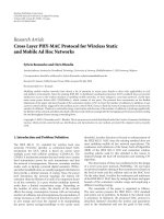
Figure 1: Generic MDC scheme with two descriptions.
low-frequency subbands are WZ-coded and sent in the de-
scriptions.
The paper is organized as follows. Section 2 gives some
background on MDC. Section 3 describes four video MDC
schemes based on different time splitting patterns and tem-
poral two- or three-band MCTF. Sections 4 and 5 show how
some robustness can be added to these schemes using sys-
tematic lossy description coding. Section 6 reports the simu-
lation results of the proposed codecs. Conclusions and per-
spectives are given in Section 7.
2. MULTIPLE DESCRIPTION CODING: BACKGROUND
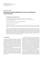
Inessence,MDCoperatesasillustratedinFigure 1.The
MDC encoder produces several correlated—but indepen-
dently decodable—bitstreams called descriptions. The mul-
tiple descriptions, each of which preferably has equivalent
quality, are sent over as many independent channels to an
MDC decoder consisting of a central decoder together with
multiple side decoders. Each of the side decoders is able to
decode its corresponding description independently of the
other descriptions, producing a representation of the source
with some level of minimally acceptable quality. On the other
hand, the central decoder can jointly decode multiple de-
scriptions to produce the best-quality reconstruction of the
source. In the simplest scenario, the transmission channels
are assumed to operate in a binary fashion; that is, if an error
occurs in a given channel, that channel is considered dam-
aged, and the entirety of the corresponding bitstream is con-
sidered unusable at the receiving end.
The success of an MDC technique hinges on path diver-
sity, which balances network load and reduces the proba-
bility of congestion. Typically, some amount of redundancy
must be introduced at the source level in order that an ac-
ceptable reconstruction can be achieved from any of the de-
scriptions, and such that reconstruction quality is enhanced
with every description received. An issue of concern is the
amount of redundancy introduced by the MDC representa-
tion with respect to a single-description coding, since there
exists a tradeoff between this redundancy and the resulting
distortion. Therefore, a great deal of effort has been spent on
analyzing the performance achievable with MDC ever since
its beginnings [6, 7] until recently, for example, [8].
Olivier Crave et al. 3
As an example of MDC, consider a wireless network
in which a mobile receiver can benefit from multiple de-
scriptions if they arrive independently, for example, on two
neighboring access points. In this case, when moving be-
tween these two access points, the receiver might capture one
or the other access point, and, in some cases, both. Another
way to take advantage of MDC in a wireless environment is
by using two frequency bands for transmitting the two de-
scriptions. For example, a laptop may be equipped with two
wireless cards (e.g., 802.11a and g) with each wireless card
receiving a different description. Depending on the dynamic
changes in the number of clients in each network, one wire-
less card may become overloaded, and the corresponding de-
scription may not be transmitted. In wired networks, differ-
ent descriptions can be routed to a receiver through differ-
ent paths by incorporating this information into the packet
header [9]. In this situation, the initial scenario of binary
“on/off ” channels might no longer be of interest. For exam-
ple, in a typical CIF-format video sequence, one frame might
be encoded into several packets. In such cases, the system
should be designed to take into consideration individual or
bursty packet losses rather than a whole description. Several
directions have been investigated for video using MDC. In
[10–13], the proposed schemes are largely deployed in the
spatial domain within hybrid video coders such as MPEG
and H.264/AVC; a thorough survey on MDC for such hybrid
coders can be found in [14].
On the other hand, only a few works investigated MDC
schemes that introduce source redundancy in the temporal
domain, although this approach has shown some promise.
In [15], a balanced interframe MDC was proposed starting
from the popular DPCM technique. In [16], the reported
MDC scheme consists of temporal subsampling of the coded
error samples by a factor of 2 so as to obtain two threads at
the encoder which are further independently encoded using
prediction loops that mimic the decoders (i.e., two-side pre-
diction loops and a central prediction loop). MDC has also
been applied to MCTF-based video coding: existing work for
t +2D video codecs with temporal redundancy addresses
3-band filter banks [17, 18]. Another direction for wavelet-
based MDC video uses the polyphase approach in the tem-
poral or spatio-temporal domain of coefficients [19–21].
3. TEMPORAL MULTIPLE DESCRIPTION
CODING SCHEMES
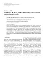
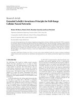
Let us first consider the scheme illustrated in Figure 2 where
odd and even frames are splitted between the two descrip-
tions. One level of a motion-compensated Haar decomposi-
tion is then applied on the frames of each description. The
temporal detail frames are encoded, while the passage from
one level to the next one is done by interleaving the approx-
imation frames from both descriptions. This new sequence
will be subsequently distributed again among the two de-
scriptions. This scheme will be called the Haar frame-level
temporal MDC (F-TMDC) scheme.
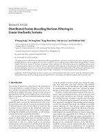
Thesecondscheme(seeFigure 3), called the Haar GOF-
level temporal MDC (G-TMDC) scheme, starts by splitting
groups of two consecutive frames between the descriptions.
LLL LLH
LH LH
Description 1
Description 2
HHHH
0 1 2 3 4 5 6 7 8 9 10 11 12 13 14 15 16 17
HHHH
LLL LLH
LH LH
Figure 2: Haar F-TMDC: odd/even temporal splitting and two-
band Haar MCTF.
LLL LLH
LH LH
Description 1
Description 2
HHHH
0 1 2 3 4 5 6 7 8 9 10 11 12 13 14 15 16 17
HHHH
LLL LLH
LH LH
Figure 3: Haar G-TMDC: frames go two by two to descriptions and
then a two-band Haar MCTF is applied in each one.
Again, one level of a Haar MCTF is applied to these couples
of frames, and the details are encoded in their respective de-
scriptions. As before, the passage from the first level to the
next one is done by interleaving the approximation frames
from the two descriptions. Next, the scheme continues as the
Haar F-TMDC scheme, by encoding with Haar MCTF odd
and even frames in different descriptions. One can remark
that it is not possible to have the same gathering as at the
first level in groups of two frames, since the temporal filtering
would be performed on approximation frames coming from
different descriptions, so in case one of them is lost, it will
not be possible to reconstruct any of them. Another remark
is that longer temporal filters would also be difficult to use
in this framework, since for all the MDC schemes presented
here, the temporal distance between frames in the same de-
scription is higher than one, and the longer the filter, the
smaller the correlation between the frames. Therefore, we re-
strict ourselves to Haar MCTF, even though the coding per-
formance of 5/3 MCTF is known to be better in absence of
losses.
In this second scheme, since the encoding is performed
on couples of successive frames, one can already expect a
better performance of the central decoder of this scheme
compared with the Haar F-TMDC scheme, where one over
two frames is considered in each description. However, in
the Haar F-TMDC scheme, when only one description is re-
ceived, the side decoder will have to reconstruct one over two
frames. The temporal distance between missing frames be-
ing only one, this task is not very difficult, and visual and
4 EURASIP Journal on Wireless Communications and Networking
LL
LH LH
Description 1
Description 2
HHHHHH
0 1 2 3 4 5 6 7 8 9 10 11 12 13 14 15 16 17
HHHHHH
LL
LH LH
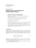
Figure 4: 3B F-TMDC: odd and even frames are separated and a
3-band MCTF is then applied in each description.
LL
LH LH
Description 1
Description 2
HH HH HH
0 1 2 3 4 5 6 7 8 9 10 11 12 13 14 15 16 17
HH HH HH
LL
LH LH
Figure 5: 3B G-TMDC: a 3-band MCTF is applied to groups of
three frames of each description.
objectiveperformancemaybeexpectedtobegood.Onthe
other hand, for the Haar G-TMDC scheme, the temporal dis-
tance between missing frames from the lost description is of
two, so their interpolation could be more complex.
The third scheme, called the 3B F-TMDC scheme, illus-
trated in Figure 4 involves a temporal splitting of the input
frames in odd and even ones, for the two descriptions, fol-
lowed by a Haar 3-band MCTF on each flow, and approxima-
tion frames are interleaved to form the new sequence at the
second decomposition level. Three-band Haar MCTF works
like two-band Haar MCTF: a predict operator is applied in
a symmetrical way between x
3t
and x
3t+1
,respectively,be-
tween x
3t
and x
3t−1
, resulting in two detail frames. Then, the
update step involves the average of the motion-compensated
details with the central frame x
3t
. Improved update operators
have been proposed for both two- and three-band schemes
[22] minimizing the reconstruction error in these spatio-
temporal filtering structures.
The last MDC scheme, called the 3B G-TMDC scheme,
is similar to the 3B F-TMDC scheme, except that groups of
three consecutive frames are separated in each description
(see Figure 5). A Haar 3-band MCTF is applied this time on
triplets. As in the case of two-band schemes, for this decom-
position, compared with the previous one, one can expect
higher performance for the central decoder. At the side de-
coders, due to the greater temporal distance between frames
used for interpolating missing ones, one may expect a deteri-
oration compared to the 3B F-TMDC scheme. Indeed, for the
3B F-TMDC scheme, the temporal distance between miss-
ing frames is only one, while for the 3B G-TMDC scheme,
the side decoders will have to interpolate from frames being
spaced of three frames to fill in gaps resulting from the loss of
one description. On the other hand, there is a gain in perfor-
mance related to the fact that the original encoding is done
on groups of consecutive frames, instead of frames spaced by
one. These two antagonist trends will be studied in Section 6.
4. SYSTEMATIC LOSSY DESCRIPTION CODING
IN THE PIXEL DOMAIN
Theschemesabovepresentdifferent tradeoffs between the
quality (PSNR and visual) of the central and lateral descrip-
tions. These tradeoffs depend on the amount of redundancy
introduced in the two descriptions. In the MDC schemes
above, the redundancy mostly results from the fact that,
given the temporal splitting of the input sequence into two
subsequences which form the descriptions, temporal corre-
lation between adjacent frames in the input sequence is not
optimally exploited. The quality of the signal reconstructed
by the side decoders can be enhanced by systematic lossy en-
coding of the descriptions. In this section and in the simula-
tion results, we only consider the 3B F-TMDC (Figure 4)and
3B G-TMDC (Figure 5)schemesofSection 3 but the Haar F-
TMDC and G-TMDC schemes can be extended in a similar
manner.
Let us first consider the MDC coding architecture de-
picted in Figure 6 (encoder) and Figure 7 (decoder). At the
encoder, the source is first divided into two sequences lead-
ing to two nonredundant descriptions of the input sequence.
Two approaches are considered for splitting the frames. In
the first one, similarly to the 3B F-TMDC scheme of the
previous section, the two subsequences are constructed by
splitting odd from even frames as shown in Figure 8, while
the second approach consists in separating the frames in
groups of three frames as shown in Figure 9 as in the 3B G-
TMDC scheme. The corresponding schemes will be referred
to as 3B frame-level distributed MDC (F-DMDC) and 3B G-
DMDC schemes. In each description, the frames of one sub-
sequence are considered as key frames while the frames of the
other are considered as Wyner-Ziv frames. The subsequence
of key frames is first temporally transformed using a Haar
3-band MCTF with two levels of temporal decomposition.
The remaining frames (Wyner-Ziv frames) are transformed
with an integer 4
× 4 block-based discrete cosine transform
(DCT) and quantized with a uniform scalar quantizer. The
transformed coefficients are structured into spatial subbands
and each bit-plane of the quantized subbands is then sepa-
rately turbo-encoded. The resulting parity bits are stored in a
buffer. At the side decoders, the key frames are decompressed
and the SI is generated by interpolating the intermediate
frames from the key frames. The turbo decoder then corrects
this SI using the parity bits. The parity sequences stored in
the buffer are transmitted in small amounts upon decoder
Olivier Crave et al. 5
Input
video
Demultiplexer
Te m p o r a l
filter
EZBC
encoder
Te m p o r a l
filter
EZBC
encoder
DCT
DCT
Turb o
encoder
Turb o
encoder
Q
Q
Coarse
quantizer
Coarse
quantizer
V2
V1
D1
D2
Figure 6: Implementation of the systematic lossy description encoder in the pixel domain.
Key
frames
Wyner-Ziv
frames
Multiplexer
Te m p o r a l
inverse filter
EZBC
decoder
DCT
−1
Turb o
decoder
Interpolation
Q
−1
Output
video
Figure 7: Implementation of the systematic lossy description side
decoder in the pixel domain.
LL
LH LH
Description 1
Description 2
HHHHHH
0 1 2 3 4 5 6 7 8 9 10 11 12 13 14 15 16 17
HHHHHH
LL
LH LH
WWWWWWWWW
WWWWWWWWW
Figure 8: 3B F-DMDC: the sequence is split into its even and odd
frames. One subsequence is conventionally encoded while the other
is WZ-encoded.
request via the feedback channel. When the estimate of the
bit error rate at the output of the decoder exceeds a given
threshold, extra parity bits are requested. This amounts to
controlling the rate of the code by selecting different punc-
turing patterns at the output of the turbo code. The bit error
rate is estimated from the log likelihood ratio on the output
bits of the turbo decoder. The correlation parameter used in
LL
LH LH
Description 1
Description 2
HH HH HH
0 1 2 3 4 5 6 7 8 9 10 11 12 13 14 15 16 17
HH HH HH
LL
LH LH
WWW WWW WWW
WWW WWW WWW
Figure 9: 3B G-DMDC: the sequence is split into groups of three
frames. One subsequence is conventionally encoded while the other
is WZ-encoded.
the turbo decoding is obtained from the residue of the mo-
tion compensated key frames.
The frames encoded as key frames in the first description
are encoded as Wyner-Ziv frames in the second description
and vice versa. Therefore, if both descriptions are received,
the decoder so far only uses the key frames to reconstruct the
sequence. On the other hand, if only one description is re-
ceived, the decoder uses the Wyner-Ziv information in the
received description to reconstruct the missing frames. The
amount of redundancy is defined by the quantization of the
Wyner-Ziv frames: the coarser the quantization, the higher
the Wyner-Ziv bitrate. So far, when the scheme is used in an
FEC scenario, the Wyner-Ziv streams are systematically sent
and discarded at the central decoder. Further work will be
dedicated to a possible use of the Wyner-Ziv bits even when
both descriptions are received in order to improve the qual-
ity of the central decoder. In the ARQ scenario, the Wyner-
Ziv streams are only sent if requested by the decoder. In the
results reported later on, only the FEC scenario is considered.
It is important to notice that the Wyner-Ziv bitrate not
only depends on the degree of quantization of the Wyner-Ziv
6 EURASIP Journal on Wireless Communications and Networking
Input
video
Demultiplexer
Te m p o r a l
filter
EZBC
encoder
Te m p o r a l
filter
EZBC
encoder
DCT
DCT
Turb o
encoder
Turb o
encoder
Q
Q
Coarse
quantizer
Coarse
quantizer
V2
V1
D1
D2
Figure 10: Implementation of the systematic lossy description encoder in the MCTF domain.
Key
frames
Wyner-Ziv
frames
Multiplexer
Multiplexer
Te m p o r a l
inverse filter
Te m p o r a l
inverse filter
Te m p o r a l
filter
EZBC
decoder
DCT
−1
Turb o
decoder
Interpolation
Q
−1
Output
video
Figure 11: Implementation of the systematic lossy description side decoder in the MCTF domain.
frames, but also on the quality of the SI, and therefore on the
degree of quantization of the key frames.
5. SYSTEMATIC LOSSY DESCRIPTION CODING
IN THE MCTF DOMAIN
To reduce the Wyner-Ziv bitrate and improve the RD perfor-
mance of the central decoder, a second architecture is pro-
posed where the Wyner-Ziv frames are first transformed by
the same Haar 3-band MCTF as the one used for the key
frames in the 3B G-TMDC scheme but with only one tem-
poral level to keep a reasonable distance between the sub-
bands. Furthermore, before entering the Wyner-Ziv encoder,
the subbands are lowpass-filtered such that only the low-
frequency subbands are WZ-encoded. The codec architec-
ture is depicted in Figures 10 (encoder) and 11 (decoder). For
this codec, the approach of separating the frames according
to the GOP size of the temporal filter is used to obtain the two
subsequences as shown in Figure 12. At the side decoders, the
SI is obtained by transforming the interpolated frames with
a Haar 3-band MCTF and the resulting low frequencies are
used as SI to decode the Wyner-Ziv subbands. To reconstruct
the frames, the decoded low-frequency subbands are com-
bined with the high-frequency subbands of the interpolated
frames to get a sequence of subbands that is finally inverse
filtered and reconstructed.
We will see in Section 6 that since only the low frequen-
cies are WZ-encoded, the RD performances at the central de-
coder should outperform the performances of the schemes
presented in the previous section.
6. SIMULATION RESULTS
6.1. Performance analysis of
the temporal MDC schemes
We first compare the four proposed MDC video coding
schemes of Section 3. They have been implemented using the
MC-EZBC software [23].Threetemporallevelsofdecompo-
sition are performed for the two-band MCTF schemes (i.e.,
the Haar F-TMDC and Haar G-TMDC schemes) and two
levels for the 3-band MCTF schemes (i.e., the 3B F-TMDC
and 3B G-TMDC schemes). The MCTF is performed us-
ing hierarchical variable-size block matching (HVSBM) al-
gorithm with block sizes varying from 64
× 64 to 4 × 4and
a 1/8th pel accuracy. Simulations have been conducted on
several test sequences, and results are presented for Foreman
and Hall Monitor, in QCIF format at 15 fps.
Olivier Crave et al. 7
LL
LH LH
Description 1
Description 2
HH HH HH
0 1 2 3 4 5 6 7 8 9 10 11 12 13 14 15 16 17
HH HH HH
LL
LH LH
LW LW LW
LW LW LW
Figure 12: 3B G-DMDC scheme in the MCTF domain: the se-
quence is split into groups of three frames. One subsequence is con-
ventionally encoded while the otheristemporallyfilteredandonly
the low-frequency subbands are WZ-encoded.
25
30
35
40
45
50
PSNR (dB)
0 200 400 600 800 1000
Rate (kBit/s)
Central decoder, Haar F-TMDC
Central decoder, Haar G-TMDC
Lateral decoder, Haar F-TMDC
Lateral decoder, Haar G-TMDC
Figure 13: Performance comparison of the Haar F-TMDC and
Haar G-TMDC schemes (Foreman, QCIF 15 fps).
The central and side RD performances of the Haar F-
TMDC and Haar G-TMDC schemes, involving two-band
MCTF, are shown in Figures 13 and 14. As expected, the cen-
tral decoder of the Haar G-TMDC scheme performs better
than that of the Haar F-TMDC scheme. The side decoder of
the Haar F-TMDC scheme slightly outperforms the one of
the Haar G-TMDC scheme. This reflects the difficulty of in-
terpolating two consecutive frames when only one descrip-
tion is received in the Haar G-TMDC scheme. For the Fore-
man sequence, one can also remark that even though the two
schemes only differ at the first temporal level of decompo-
sition, the gap between their coding performances is quite
large (around 2 dB and 1 dB for the central and side decoders,
resp.). The performance gap is lower for the Hall Monitor se-
30
32
34
36
38
40
42
44
PSNR (dB)
40 60 80 100 120 140 160 180 200
Rate (kBit/s)
Central decoder, Haar F-TMDC
Central decoder, Haar G-TMDC
Lateral decoder, Haar F-TMDC
Lateral decoder, Haar G-TMDC
Figure 14: Performance comparison of the Haar F-TMDC and
Haar G-TMDC schemes (Hall Monitor, QCIF 15 fps).
25
30
35
40
45
50
PSNR (dB)
0 200 400 600 800 1000
Rate (kBit/s)
Central decoder, 3-band F-TMDC
Central decoder, 3-band G-TMDC
Lateral decoder, 3-band F-TMDC
Lateral decoder, 3-band G-TMDC
Figure 15: Performance comparison of the 3B F-TMDC and 3B G-
TMDC schemes (Foreman, QCIF 15 fps).
quence (0.5 dB for the central decoders and only 0.25 dB for
the side decoders).
TheRDperformanceofthe3BF-TMDCand3BG-
TMDC schemes, based on 3-band MCTF, is illustrated in
Figures 15 and 16. As in the case of two-band MCTF
schemes, grouping consecutive frames before filtering and
encoding them in different descriptions leads, as expected,
to better results for the central decoder of the 3B G-TMDC
scheme. An improvement of up to 1.5 dB for the Foreman
8 EURASIP Journal on Wireless Communications and Networking
30
32
34
36
38
40
42
44
PSNR (dB)
40 60 80 100 120 140 160 180 200
Rate (kBit/s)
Central decoder, 3-band F-TMDC
Central decoder, 3-band G-TMDC
Lateral decoder, 3-band F-TMDC
Lateral decoder, 3-band G-TMDC
Figure 16: Performance comparison of the 3B F-TMDC and 3B G-
TMDC schemes (Hall Monitor, QCIF 15 fps).
sequence and 0.5 dB for Hall Monitor has been obtained.
This improvement is however obtained at the expense of a
PSNR loss (of up to 2 dB for Foreman and 1 dB for Hall Mon-
itor) of the side decoders. The side decoders need to interpo-
late three missing frames from frames which are temporally
distant.
6.2. Performance analysis of
the distributed MDC schemes
The PSNR and visual performance advantage brought by
the Wyner-Ziv encoded data is then assessed. The results of
the 3B F-DMDC and G-DMDC schemes are thus compared
against the performance of the 3B MDC scheme [18]; it is
based on the same 3-band MCTF but with temporal redun-
dancy added by subsampling the temporal 3-band structure
by a factor 2, instead of a factor 3.
The tests have been performed for four rate-distortion
points for the Wyner-Ziv bitrate corresponding to the 4
×
4 quantization matrices depicted in Figure 17. Within a 4 ×
4 quantization matrix, the value at position k in Figure 17
indicates the number of quantization levels associated to the
DCT coefficients band b
k
; the value 0 means that no Wyner-
Ziv bits are transmitted for the corresponding band. In the
following, the various matrices will be referred to as Q
i
with
i
= 1, , 4. The higher the index i, the higher the bitrate and
the quality.
The bitrates used for the key frames are 20, 40, 60, 80,
100, 150, and 200 kBit/s for Hall Monitor and 80, 100, 150,
200, 250, 500, and 1000 kBit/s for Foreman. Figures 18 and
19 show the performances of the 3B F-DMDC scheme at
the central decoder for Foreman and Hall Monitor. The bi-
trate corresponds to the global rate (both descriptions). For
Hall Monitor, the 3B F-TMDC scheme systematically out-
16 8 0 0
8000
0000
0000
Q
1
32 8 0 0
8000
0000
0000
Q
2
32 8 4 0
8400
4000
0000
Q
3
32 16 8 4
16 8 4 0
8400
4000
Q
4
Figure 17: Four quantization matrices associated to different RD
performances.
25
30
35
40
45
50
PSNR (dB)
0 200 400 600 800 1000 1200
Rate (kBit/s)
3-band F-TMDC
3-band F-DMDC, Q
1
3-band F-DMDC, Q
2
3-band F-DMDC, Q
3
3-band F-DMDC, Q
4
3-band MDC
Figure 18: Central distortions of the 3B F-DMDC scheme com-
pared with the 3B MDC codec (Foreman, QCIF 15 fps).
performs the 3B MDC scheme (+1 dB) but performs worse
(
−0.5 dB) in the case of Foreman. As expected, when a
Wyner-Ziv stream is added to the descriptions, the PSNR val-
ues decrease. Figures 20 and 21 show the performances of the
3B F-DMDC scheme at the side decoder. This time, the 3B
F-DMDC scheme slightly outperforms the 3B MDC scheme
with or without extra information, especially for Foreman
and for the highest bitrates.
A comparison of the schemes only in terms of mean
PSNR (the average PSNR between the frames being received
and the frames being lost and interpolated with or without
extra information) is not sufficient because the PSNR fluc-
Olivier Crave et al. 9
28
30
32
34
36
38
40
42
44
PSNR (dB)
0 50 100 150 200 250 300
Rate (kBit/s)
3-band F-TMDC
3-band F-DMDC, Q
1
3-band F-DMDC, Q
2
3-band F-DMDC, Q
3
3-band F-DMDC, Q
4
3-band MDC
Figure 19: Central distortions of the 3B F-DMDC scheme com-
pared with the 3B MDC codec (Hall Monitor, QCIF 15 fps).
26
28
30
32
34
36
38
40
42
PSNR (dB)
0 200 400 600 800 1000 1200
Rate (kBit/s)
3-band F-TMDC
3-band F-DMDC, Q
1
3-band F-DMDC, Q
2
3-band F-DMDC, Q
3
3-band F-DMDC, Q
4
3-band MDC
Figure 20: Side distortions of the 3B F-DMDC scheme compared
with the 3B MDC codec (Foreman, QCIF 15 fps).
tuations in time are not taken into account. Figure 24 shows
the PSNR variation from the 50th to the 100th frame of the
Foreman sequence at 307 kBit/s for the 3B F-DMDC scheme
using the quantization matrix Q
1
and the 3B MDC scheme
at the central and side decoders. At the side decoder, this
figure shows that the PSNR values of the 3B MDC scheme
drop sharply (as low as 16.5 dB) when the missing frames
are simply interpolated, whereas it is more stable for the
3B F-DMDC scheme (the lowest value being 25.9dB),even
though the mean PSNR value is only 1 dB lower for the 3B
26
28
30
32
34
36
38
40
42
PSNR (dB)
0 50 100 150 200 250 300
Rate (kBit/s)
3-band F-TMDC
3-band F-DMDC, Q
1
3-band F-DMDC, Q
2
3-band F-DMDC, Q
3
3-band F-DMDC, Q
4
3-band MDC
Figure 21: Side distortions of the 3B F-DMDC scheme compared
with the 3B MDC codec (Hall Monitor, QCIF 15 fps).
0
0.2
0.4
0.6
0.8
1
1.2
1.4
1.6
1.8
Va ri an ce
0 200 400 600 800 1000 1200
Rate (kBit/s)
3-band F-TMDC
3-band F-DMDC, Q
1
3-band F-DMDC, Q
2
3-band F-DMDC, Q
3
3-band F-DMDC, Q
4
3-band MDC
Figure 22: PSNR variations at the central decoder of the 3B F-
DMDC scheme in the MCTF domain compared with the 3B MDC
codec (Foreman, QCIF 15 fps).
MDC scheme than for the 3B F-DMDC scheme. However,
at the central decoder, the 3B MDC scheme performs bet-
ter than the 3B F-DMDC scheme (+2.2 dB) because the data
contained in the Wyner-Ziv bitstream is simply discarded
and does not contribute to the central decoding.
Figures 22 and 23 show the variations in PSNR between
the frames at the central and side decoders. At the central
decoder, the variance is higher for the F-DMDC scheme
than for the 3-band F-TDMC and 3-band MDC schemes but
remains reasonable (less than 1.8). At the side decoders, the
10 EURASIP Journal on Wireless Communications and Networking
0
20
40
60
80
100
120
140
Va ri an ce
0 200 400 600 800 1000 1200
Rate (kBit/s)
3-band F-TMDC
3-band F-DMDC, Q
1
3-band F-DMDC, Q
2
3-band F-DMDC, Q
3
3-band F-DMDC, Q
4
3-band MDC
Figure 23: PSNR variations at the side decoder of the 3B F-DMDC
scheme compared with the 3B MDC codec (Foreman, QCIF 15 fps).
10
15
20
25
30
35
40
PSNR (dB)
50 60 70 80 90 100
Frame number
Central decoder, 3-band F-DMDC, Q
1
Central decoder, 3-band MDC
Lateral decoder, 3-band F-DMDC, Q
1
Lateral decoder, 3-band MDC
Figure 24: Central and lateral PSNR variation from the 50th to the
100th frame of the Foreman sequence (QCIF, 15 fps) at 307 kBit/s.
use of an additional Wyner-Ziv bitstream dramatically re-
duces the PSNR variations with gains that could reach 100
compared to the 3-band MDC scheme at 1000 kBit/s. This
figure clearly shows the benefit of using higher values of Q
i
at the side decoders; Q
4
being more stable than all the other
schemes.
Figures 25 and 26 show the performances of the 3B
G-DMDC scheme at the central decoder for Foreman and
Hall Monitor. As expected, the coding performances are bet-
ter than the ones with the 3B F-TMDC scheme and, this
30
32
34
36
38
40
42
44
46
48
50
PSNR (dB)
0 200 400 600 800 1000 1200 1400
Rate (kBit/s)
3-band G-TMDC
3-band G-DMDC, Q
1
3-band G-DMDC, Q
2
3-band G-DMDC, Q
3
3-band G-DMDC, Q
4
3-band MDC
Figure 25: Central distortions of the 3B G-DMDC scheme com-
pared with the 3B MDC codec (Foreman, QCIF 15 fps).
24
26
28
30
32
34
36
38
40
42
44
PSNR (dB)
0 50 100 150 200 250 300
Rate (kBit/s)
3-band G-TMDC
3-band G-DMDC, Q
1
3-band G-DMDC, Q
2
3-band G-DMDC, Q
3
3-band G-DMDC, Q
4
3-band MDC
Figure 26: Central distortions of the 3B G-DMDC scheme com-
pared with the 3B MDC codec (Hall Monitor, QCIF 15 fps).
time, the 3B G-TMDC scheme systematically outperforms
the 3B MDC scheme (+1.5 dB for Foreman and +2 dB for
Hall Monitor). However, the 3B G-DMDC scheme with an
added WZ-encoded stream still performs worse than the 3B
MDC scheme especially for the lower bitrates, and the higher
Q
i
is, the lower the RD performances are at the central de-
coder. Figures 27 and 28 show the performances of the 3B
G-DMDC scheme at the side decoder. The 3B MDC scheme
is outperformed even though the interpolation is done for
three consecutive frames. As one can see, the 3B G-DMDC
Olivier Crave et al. 11
26
28
30
32
34
36
38
40
42
PSNR (dB)
0 200 400 600 800 1000 1200 1400
Rate (kBit/s)
3-band G-TMDC
3-band G-DMDC, Q
1
3-band G-DMDC, Q
2
3-band G-DMDC, Q
3
3-band G-DMDC, Q
4
3-band MDC
Figure 27: Side distortions of the 3B G-DMDC scheme compared
with the 3B MDC codec (Foreman, QCIF 15 fps).
24
26
28
30
32
34
36
38
40
42
PSNR (dB)
0 50 100 150 200 250 300
Rate (kBit/s)
3-band G-TMDC
3-band G-DMDC, Q
1
3-band G-DMDC, Q
2
3-band G-DMDC, Q
3
3-band G-DMDC, Q
4
3-band MDC
Figure 28: Side distortions of the 3B G-DMDC scheme compared
with the 3B MDC codec (Hall Monitor, QCIF 15 fps).
scheme does not perform well compared to the 3B F-DMDC
scheme because of the important amount of parity bits that
are requested at the turbo decoding due to the bad quality of
the SI.
Creating the two descriptions by splitting the sequence
into even and odd subsequences makes the temporal filter-
ing less efficient, the correlation between the frames is weaker
and it results in poor RD performances at the central de-
coder. Furthermore, by sending Wyner-Ziv data for all the
frames of the sequence, we end up with a totally redundant
scheme. To solve this problem, we propose a 3B G-DMDC
30
32
34
36
38
40
42
44
46
48
50
PSNR (dB)
0 200 400 600 800 1000 1200
Rate (kBit/s)
3-band G-TMDC
3-band G-DMDC in the MCTF domain, Q
1
3-band G-DMDC in the MCTF domain, Q
2
3-band G-DMDC in the MCTF domain, Q
3
3-band G-DMDC in the MCTF domain, Q
4
3-band MDC
Figure 29: Central distortions of the 3B G-DMDC scheme in the
MCTF domain compared with the 3B MDC codec (Foreman, QCIF
15 fps).
24
26
28
30
32
34
36
38
40
42
44
PSNR (dB)
0 50 100 150 200 250
Rate (kBit/s)
3-band G-TMDC
3-band G-DMDC in the MCTF domain, Q
1
3-band G-DMDC in the MCTF domain, Q
2
3-band G-DMDC in the MCTF domain, Q
3
3-band G-DMDC in the MCTF domain, Q
4
3-band MDC
Figure 30: Central distortions of the 3B G-DMDC scheme in the
MCTF domain compared with the 3B MDC codec (Hall Monitor,
QCIF 15 fps).
scheme in the MCTF domain where the frame splitting is
done as in Figure 12 and only the low-frequency subbands
are WZ-encoded.
Figures 29 and 30 show the performances of the 3B G-
DMDC scheme in the MCTF domain at the central decoder
12 EURASIP Journal on Wireless Communications and Networking
26
28
30
32
34
36
38
40
PSNR (dB)
0 200 400 600 800 1000 1200
Rate (kBit/s)
3-band G-TMDC
3-band G-DMDC in the MCTF domain, Q
1
3-band G-DMDC in the MCTF domain, Q
2
3-band G-DMDC in the MCTF domain, Q
3
3-band G-DMDC in the MCTF domain, Q
4
3-band MDC
Figure 31: Side distortions of the 3B G-DMDC scheme in the
MCTF domain compared with the 3B MDC codec (Foreman, QCIF
15 fps).
for Foreman and Hall Monitor. It performs better than the
3B MDC scheme for the smallest values of Q
i
(i<4) and
the higher bitrates (starting at around 300 kBit/s for Fore-
man and 60 kBit/s for Hall Monitor). At the same time, the
performance at the side decoder shown in Figures 31 and 32
is still better than that of the 3B MDC scheme even though it
is lower than the ones of the 3B F-DMDC and 3B G-DMDC
schemes.
7. CONCLUSION AND FUTURE WORK
In this paper, a video MDC architecture based on temporal
splitting of the frames in a sequence followed by MCTF has
been considered. It has first been generalized to a temporal
splitting of groups of frames and to 3-band MCTF. Experi-
mental results have shown that grouping consecutive frames
before filtering and encoding them in different descriptions
provides better results at the central decoder and worse re-
sults at the side decoders than directly separating even and
odd frames. This effect is even more visible for high-motion
sequences.
Two systematic lossy description coding schemes, where
missing frames in each description are Wyner-Ziv encoded,
have then been introduced in order to limit the strong quality
time variations of the side descriptions of the temporal MDC
approaches. The results show that both schemes perform
better than the 3B MDC scheme at the side decoders for most
of the bitrates and that the variation in quality between the
frames is reduced, leading to less artifacts. However, the RD
performances at the central decoder are always worse than
that of the 3B MDC scheme even though the same schemes
24
26
28
30
32
34
36
38
40
PSNR (dB)
0 50 100 150 200 250
Rate (kBit/s)
3-band G-TMDC
3-band G-DMDC in the MCTF domain, Q
1
3-band G-DMDC in the MCTF domain, Q
2
3-band G-DMDC in the MCTF domain, Q
3
3-band G-DMDC in the MCTF domain, Q
4
3-band MDC
Figure 32: Side distortions of the 3B G-DMDC scheme in the
MCTF domain compared with the 3B MDC codec (Hall Monitor,
QCIF 15 fps).
without extra information perform better. This is due to the
fact that, so far when used as an FEC mechanism, the Wyner-
Ziv information is simply discarded when both descriptions
are received and does not contribute to any improvement in
the central decoding quality. Note that in presence of a return
channel, the amount of WZ data can be controlled accord-
ing to the impairments observed on the transmission chan-
nel. In order to have a finer tuning of the rate of the Wyner-
Ziv data which has a strong impact on the tradeoff between
central and side description quality, when used as an FEC
mechanism, the schemes have then been extended to the case
where the Wyner-Ziv frames are first temporally filtered and
only the low-frequency subbands are WZ-encoded and sent
as extra redundancy in the descriptions. The results showed
that this scheme can outperform the 3B MDC scheme for the
highest bitrates and the lowest quantization indices. The RD
performance at the side decoders does not suffer too much
from the fact that no Wyner-Ziv information is sent for the
high-frequency subbands.
ACKNOWLEDGMENT
The developments have been partly based on the distributed
video coding software developed by the European Discover
consortium which has been built upon the IST-TDWZ codec
[24].
REFERENCES
[1] V. K. Goyal, “Multiple description coding: compression meets
the network,” IEEE Signal Processing Magazine, vol. 18, no. 5,
pp. 74–93, 2001.
Olivier Crave et al. 13
[2] S. Shamai, S. Verd
´
u, and R. Zamir, “Systematic lossy source/
channel coding,” IEEE Transactions on Informat ion Theory,
vol. 44, no. 2, pp. 564–579, 1998.
[3] S. Rane, A. Aaron, and B. Girod, “Systematic lossy forward er-
ror protection for error-resilient digital video broadcasting,”
in Visual Communications and Image Processing (VCIP ’04),
vol. 5308 of Proceedings of SPIE, pp. 588–595, San Jose, Calif,
USA, January 2004.
[4] A. Sehgal, A. Jagmohan, and N. Ahuja, “Wyner-Ziv coding of
video: an error-resilient compression framework,” IEEE Trans-
actions on Multimedia, vol. 6, no. 2, pp. 249–258, 2004.
[5] C. Tillier and B. Pesquet-Popescu, “3D, 3-band, 3-TAP tem-
poral lifting for scalable video coding,” in Proceedings of IEEE
International Conference on Image Processing (ICIP ’03), vol. 2,
pp. 779–782, Barcelona, Spain, September 2003.
[6] L. Ozarow, “On a source-coding problem with two channels
and three receivers,” TheBellSystemTechnicalJournal, vol. 59,
no. 10, pp. 1909–1921, 1980.
[7] A. El Gamal and T. Cover, “Achievable rates for multiple de-
scriptions,” IEEE Transactions on Information Theory, vol. 28,
no. 6, pp. 851–857, 1982.
[8] R. Venkataramani, G. Kramer, and V. K. Goyal, “Multiple de-
scription coding with many channels,” IEEE Transactions on
Information Theory, vol. 49, no. 9, pp. 2106–2114, 2003.
[9] J. G. Apostolopoulos, “Reliable video communication over
lossy packet networks using multiple state encoding and path
diversity,” in Visual Communications and Image Processing
(VCIP ’01), B. Girod, C. A. Bouman, and E. G. Steinbach, Eds.,
vol. 4310 of Proceedings of SPIE, pp. 392–409, San Jose, Calif,
USA, January 2001.
[10] W.S.Lee,M.R.Pickering,M.R.Frater,andJ.F.Arnold,“A
robust codec for transmission of very low bit-rate video over
channels with bursty errors,” IEEE Transactions on Circuits and
Systems for Video Technology, vol. 10, no. 8, pp. 1403–1412,
2000.
[11] A. R. Reibman, H. Jafarkhani, Y. Wang, M. T. Orchard, and
R. Puri, “Multiple-description video coding using motion-
compensated temporal prediction,” IEEE Transactions on Cir-
cuits and Systems for Video Technology, vol. 12, no. 3, pp. 193–
204, 2002.
[12] I. V. Bajic and J. W. Woods, “Domain-based multiple descrip-
tion coding of images and video,” IEEE Transactions on Image
Processing, vol. 12, no. 10, pp. 1211–1225, 2003.
[13] N. Franchi, M. Fumagalli, R. Lancini, and S. Tubaro, “Multiple
description video coding for scalable and robust transmission
over IP,” IEEE Transactions on Circuits and Systems for Video
Technology, vol. 15, no. 3, pp. 321–334, 2005.
[14] Y. Wang, A. R. Reibman, and S. Lin, “Multiple description cod-
ing for video delivery,” Proceedings of the IEEE, vol. 93, no. 1,
pp. 57–70, 2005.
[15] V. A. Vaishampayan and S. John, “Balanced interframe mul-
tiple description video compression,” in Proceedings of IEEE
International Conference on Image Processing (ICIP ’99), vol. 3,
pp. 812–816, Kobe, Japan, October 1999.
[16] Y. Wang and S. Lin, “Error-resilient video coding using mul-
tiple description motion compensation,” IEEE Transactions on
Circuits and Systems for Video Technology,vol.12,no.6,pp.
438–452, 2002.
[17] M. van der Schaar and D. S. Turaga, “Multiple descrip-
tion scalable coding using wavelet-based motion compensated
temporal filtering,” in Proceedings of IEEE International Con-
ference on Image Processing (ICIP ’03), vol. 3, pp. 489–492,
Barcelona, Spain, September 2003.
[18] C. Tillier, B. Pesquet-Popescu, and M. van der Schaar, “Multi-
ple descriptions scalable video coding,” in Proceedings of the
12th European Signal Processing Conference (EUSIPCO ’04),
Vienna, Austria, September 2004.
[19] J. Kim, R. M. Mersereau, and Y. Altunbasak, “Network-
adaptive video streaming using multiple description coding
and path diversity,” in Proceedings of IEEE International Con-
ference on Multimedia & Expo (ICME ’03), vol. 2, pp. 653–656,
Baltimore, Md, USA, July 2003.
[20] N. Franchi, M. Fumagalli, G. Gatti, and R. Lancini, “A novel
error-resilience scheme for a 3-D multiple description video
coder,” in Proceedings of the Picture Coding Symposium,pp.
373–376, San Francisco, Calif, USA, December 2004.
[21] S. Cho and W. A. Pearlman, “Error resilient compression and
transmission of scalable video,” in Applications of Digital Image
Processing XXIII, A. G. Tescher, Ed., vol. 4115 of Proceedings of
SPIE, pp. 396–405, San Diego, Calif, USA, July-August 2000.
[22] C. Tillier, B. Pesquet-Popescu, and M. van der Schaar,
“Improved update operators for lifting-based motion-
compensatedtemporalfiltering,”IEEE Signal Processing
Letters, vol. 12, no. 2, pp. 146–149, 2005.
[23] P. Chen and J. W. Woods, “Bidirectional MC-EZBC with lift-
ing implementation,” IEEE Transactions on Circuits and Sys-
tems for Video Technology, vol. 14, no. 10, pp. 1183–1194, 2004.
[24] C. Brites, J. Ascenso, and F. Pereira, “Improving transform do-
main Wyner-Ziv video coding performance,” in Proceedings of
IEEE Internat ional Conference on Acoustics, Speech, and Signal
Processing (ICASSP ’06), vol. 2, pp. 525–528, Toulouse, France,
May 2006.