Báo cáo hóa học: " Research Article Reverse Link Outage Probabilities of Multicarrier CDMA Systems with Beamforming in the Presence of Carrier Frequency Offset" doc
Bạn đang xem bản rút gọn của tài liệu. Xem và tải ngay bản đầy đủ của tài liệu tại đây (793.7 KB, 9 trang )
Hindawi Publishing Corporation
EURASIP Journal on Wireless Communications and Networking
Volume 2008, Article ID 218740, 9 pages
doi:10.1155/2008/218740
Research Article
Reverse Link Outage Probabilities of Multicarrier
CDMA Systems with Beamforming in the Presence of
Carrier Frequency Offset
Xiaoyu Hu and Yu-Dong Yao
Wireless Information System Engineering Laboratory (WISELAB), Department of Electrical and Computer Enginee ring,
Stevens Institute of Technology, Hoboken, NJ 07030, USA
Correspondence should be addressed to Yu-Dong Yao,
Received 30 April 2007; Revised 28 August 2007; Accepted 25 September 2007
Recommended by Hikmet Sari
The outage probability of reverse link multicarrier (MC) code-division multiple access (CDMA) systems with beamforming in
the presence of carrier frequency offset (CFO) is studied. A conventional uniform linear array (ULA) beamformer is utilized. An
independent Nakagami fading channel is assumed for each subcarrier of all users. The outage probability is first investigated under
a scenario where perfect beamforming is assumed. A closed form expression of the outage probability is derived. The impact of
different types of beamforming impairments on the outage probability is then evaluated, including direction-of-arrival (DOA)
estimation errors, angle spreads, and mutual couplings. Numerical results show that the outage probability improves significantly
as the number of antenna elements increases. The effect of CFO on the outage probability is reduced significantly when the beam-
forming technique is employed. Also, it is seen that small beamforming impairments (DOA estimation errors and angle spreads)
only affect the outage probability very slightly, and the mutual coupling between adjacent antenna elements does not affect the
outage probability noticeably.
Copyright © 2008 X. Hu and Y D. Yao. This is an open access article distributed under the Creative Commons Attribution
License, which permits unrestricted use, distribution, and reproduction in any medium, provided the original work is properly
cited.
1. INTRODUCTION
Future wireless communication systems demand high-data-
rate multimedia transmissions in diverse mobile environ-
ments. The underlying wideband nature makes the overall
system vulnerable to the hostile frequency-selective multi-
path fading. Code-division multiple access (CDMA) has re-
ceived tremendous attentions because it offers various attrac-
tive features such as high spectrum efficiency, narrow-band
interference rejection, and soft capacity [1, 2]. Recently, the
multicarrier (MC) CDMA system, which is a combination
of orthogonal frequency division multiplexing (OFDM) and
CDMA, has gained significant interests as a powerful can-
didate for future wireless broadband communications [3].
Multicarrier CDMA inherits distinct advantages from both
OFDM and CDMA. By dividing the full available bandwidth
into a large number of small orthogonal narrow bands or
subcarriers each having bandwidth much less than the chan-
nel coherent bandwidth, the transmission over each subcar-
rier will experience frequency nonselective fading. Also, it
can be interpreted as CDMA with spreading taking place in
the frequency domain rather than temporal domain, achiev-
ing enhanced frequency diversity. MC-CDMA is basically a
multicarrier transmission scheme and its receiver is vulner-
able to carrier frequency offset (CFO) which is due to the
mismatch in frequencies between the local oscillators in the
transmitter and the receiver.
Antenna array techniques are used to reduce interference
to meet increased capacity requirements without sacrificing
the frequency spectrum [4, 5], which can be realized through
space diversity, beamforming, and spatial multiplexing [6].
In this paper, the use of conventional uniform linear array
(ULA) beamformer [16] is to provide performance improve-
ments in MC-CDMA systems, especially with the considera-
tion of CFO.
The outage probability is an important performance
measure in the design of wireless communication systems,
which represents the probability of unsatisfactory reception
2 EURASIP Journal on Wireless Communications and Networking
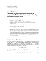
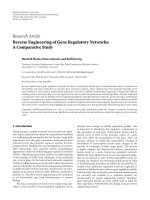
0.5λ
θ
Incident wave
y
x
Figure 1: ULA antenna array.
over an intended coverage area. The performance in terms
of the bit-error rate (BER) for MC-CDMA systems has
been investigated in a number of literatures, either assum-
ing perfect carrier frequency synchronization [8, 9]orwith
CFO [10–13]. There have been several papers studying the
outage probability performance in various CDMA systems
[14, 15, 18]. However, MC-CDMA systems have not been ex-
amined in such studies.
In this paper, the reverse link of an MC-CDMA system
with the beamforming technique in the presence of CFO is
considered, and we concentrate the analysis on the outage
probability performance. A Nakagami fading channel is as-
sumed throughout the paper. Based on a newly developed
simplified beamforming model [18], a closed-form expres-
sion is derived for the outage probability when perfect beam-
forming is considered. The impact of CFO and beamform-
ing is modeled in signal and interference expressions. Fur-
thermore, the effect of various beamforming impairments
is examined, including direction-of-arrival (DOA) estima-
tion errors, angle spreads, and mutual couplings. To sum-
marize, this paper differs from previous research mainly in
two aspects: first, we develop signal and interference mod-
els to characterize the beamforming gain and CFO in MC-
CDMA systems; second, outage probabilities are derived for
MC-CDMA systems with either perfect or imperfect beam-
forming in the presence of CFO.
The remainder of the paper is organized as follows. The
system model is described in Section 2. The outage proba-
bility for MC-CDMA with beamforming in the presence of
CFO is presented in Section 3. The effect of impairments
in beamforming is investigated in Section 4.Numericalre-
sults are presented and discussed in Section 5. Conclusions
are given in Section 6.
2. SYSTEM MODEL
2.1. Beamforming
Due to the space limitation of mobile terminals, few antenna
elements can be employed at the mobile station (MS). While
at the base station (BS), a large number of antenna elements
can be implemented in an array. Considering receive beam-
forming in reverse-link transmissions, signals from these an-
tenna elements are combined to form a movable beam pat-
tern that can be steered to a desired direction to track the MS
as it moves [17, 18]. When beamforming is used at the MS,
the transmit beam pattern can be adjusted to minimize in-
terference to unintended receivers. At the BS, receive beam-
forming for each desired user could be implemented inde-
pendently without affecting the performance of other links
[17, 18]. A ULA beamformer is considered and shown in
Figure 1,inwhichθ is an arrival angle. In this paper, a two-
dimension (2D) single-cell environment is considered. The
distance d between elements of the ULA array is assumed to
be 0.5λ,whereλ is the carrier wavelength. In the ULA ar-
ray system, a combining network connects an array of low-
gain antenna elements and could generate an antenna pat-
tern [17, 19]:
G(θ, ψ)
=
sin
0.5Mπ(sin θ −sin ψ)
M sin
0.5π(sin θ −sin ψ)
2
,(1)
where M is the number of antenna elements and ψ is a scan
angle. The beam could be steered to a desired direction by
varying ψ, that is to say, setting ψ equal to the arrival an-
gle θ of the desired signal. Hereafter, we will use the antenna
pattern specified in (1) to evaluate the outage probability for
MC-CDMA systems with beamforming in reverse link trans-
missions.
2.2. Simplified beamforming model
The analytical complexity in evaluating the exact beam pat-
tern is very high when a large number of interfering users
are present in the MC-CDMA system, especially for the in-
vestigation of effects of beamforming impairments such as
DOA estimation errors, angle spreads, and mutual couplings.
A simplified Bernoulli model is introduced in [20]where
the signal is considered to be either within the mainlobe
(G
= 1) or out of the mainlobe (G = 0) and the half-power
beamwidth is defined as the beamwidth. This model is easy
to use but it neglects the impact of sidelobes and the effect of
any specific beam patterns. Spagnolini provides a beamform-
ing model in [21] with a triangular pattern to characterize the
beam head. A beamforming model that takes into account
the impact of sidelobes and the actual beam patterns is in-
troduced in [18]. The beamwidth is assumed to be B which
is normalized by 2π. The gain of the mainlobe is normalized
to unity, while the gain in sidelobe is α. This implies that one
interferer stays in the mainlobe with probability B. Consid-
ering an exact beam pattern and normalizing the pattern by
the gain at the desired direction, these two parameters α and
B are determined by
α
=
E
G
2
(θ, ψ)
−
E
G(θ, ψ)
E{G(θ, ψ)}−1
,
B
=
E
G
2
(θ, ψ)
− E
2
G(θ, ψ)
E
G
2
(θ, ψ)
+1−2E
G(θ, ψ)
,
(2)
X. Hu and Y D. Yao 3
90
120
150
180
210
240
270
300
330
60
30
0
M
= 2
M
= 3
0.2
0.4
0.6
0.8
1
(a) Signal model
90
120
150
180
210
240
270
300
330
60
30
0
M
= 2
M
= 3
0.2
0.4
0.6
0.8
1
(b) Interference mode
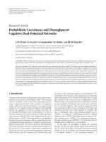
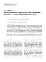
Figure 2: A simplified beamforming model with arrival angle θ = 30
◦
.
where E{G(θ, ψ)} and E{G
2
(θ, ψ)} are the first and second
moments of the antenna gain, respectively, averaged with re-
spect to uniformly distributed random variables (RVs) θ and
ψ from 0 to 2π. We have to point out that throughout the
paper the desired user still uses the exact beam pattern as
illustrated in Figure 2(a), nevertheless, multiuser interferers
will use the above simplified beam pattern with parameters α
and B as shown in Figure 2(b) in performance evaluations.
2.3. MC-CDMA
A reverse link MC-CDMA system with beamforming in the
presence of CFO is considered. The number of subcarriers is
chosen so that the bit duration is assumed to be much longer
than channel delay spread such that the signal in each subcar-
rier will undergo flat fading. Suppose that there are K asyn-
chronous users, each employing L subcarriers and using bi-
nary phase-shift keying (BPSK) with the same power S and
bit duration T
b
. The signal is spread in the frequency domain
with the spreading gain L which is also equal to the number
of subcarriers. Δ f
k
is the CFO between oscillators of the kth
user’s transmitter and the receiver of the BS. The Nakagami-
m fading channel is assumed over each subcarrier with its
probability density function (PDF):
f
β
k,l
β
k,l
=
2m
m
β
2m−1
k,l
Ω
m
Γ(m)
exp
−
mβ
2
k,l
Ω
l = 0, 1, , L −1,
(3)
where β
k,l
is the channel fading gain on the lth subcarrier of
the kth user and is assumed to be independent for different l
and k, m is the Nakagami-m fading parameter which ranges
from 1/2to
∞, Ω=E{β
2
k,l
},andΓ(z) =
∞
0
e
−t
t
z−1
dt is a gam-
ma function.
Assuming that the maximum ratio combining (MRC)
technique is used, and following [10, 11, 18], the received
signal can be expressed as
U
=
L−1
l=0
√
Ξ β
2
0,l
+ I,(4)
where Ξ = 2[SG
t
(θ
0
− π, θ
0
− π)G
r
(θ
0
, ψ)]·sinc
2
(ε), and
I represents the interference and noise items. Hence, the re-
ceived power from desired 0th user can be expressed as
E
b
=2
SG
t
θ
0
−π, θ
0
−π
G
r
θ
0
, ψ
·sinc
2
(ε)
L−1
l=0
β
2
0,l
2
,
(5)
where G
t
(θ
0
−π, θ
0
−π)andG
r
(θ
0
, ψ) are the transmit and
receive beamforming gain, respectively; θ
0
− π and θ
0
are
the transmit angle and arrival angle from the 0th user to the
BS, respectively; ψ is the estimated arrival angle that is used
to steer the beam to the desired 0th user and is assumed to
be equal to θ
0
, that is, ψ = θ
0
; sinc (x) = sin(πx)/πx and
ε
= Δ f
0
T
b
is the normalized CFO (NCFO) for the desired
0th user, and assume that ε
∈ [0, 1]; denote ε
k
= Δ f
k
T
b
(k =
1, , K −1) as the NCFO for the kth interfering user which
is uniformly distributed over [0, ε]. Figure 3 indicates angle
notations in transmit beamforming at the MS and receive
beamforming at the BS.
The interference power E
I
can be divided into three parts
[10], self-interference (SI) from other subcarriers E
so
,mul-
tiuser interference (MUI) from the same subcarriers E
ms
,
4 EURASIP Journal on Wireless Communications and Networking
y
θ
x
θ
−π
MS
BS
Figure 3: Angle notations for transmit beamforming and receive
beamforming.
and MUI from other subcarriers E
mo
.Hence,wehaveE
I
=
E
so
+ E
ms
+ E
mo
. The SI power E
so
can be written as
E
so
=
SG
t
(θ
0
−π, θ
0
−π)G
r
(θ
0
, ψ)
Ω
·
L−1
l=0
L
−1
h=0,h=l
sinc
2
(l −h −ε)·β
2
0,l
.
(6)
The interference power E
ms
can be expressed as
E
ms
=
K−1
k=1
SG
t
θ
k
−π, θ
k
−π
G
r
θ
k
, ψ
Ω
π
2
ε
2
·
−1+
p
F
q
−
1
2
;
1
2
,
2
3
; −π
2
ε
2
L−1
l=0
β
2
0,l
,
(7)
where G
t
(θ
k
−π, θ
k
−π)andG
r
(θ
k
, ψ) are the transmit and
receive beamforming gain, respectively; θ
k
− π and θ
k
are
the transmit angle and arrival angle from the kth user to the
BS, respectively;
p
F
q
(a; b; z) is a generalized hypergeometric
function [22], and the interference power E
mo
is given by
E
mo
=
K−1
k=1
SG
t
θ
k
−π, θ
k
−π
G
r
θ
k
, ψ
Ω
π
2
ε
·
L−1
l=0
L
−1
h=0,h=1
[g(l − h, ε) − g(l − h,0)]·β
2
0,l
,
(8)
where
g(x, y)
=
1
2(x − y)
2 − cos
2π(x − y)
−sinc
2 − (x − y)
−
2π(x − y)Si
2π(x − y)
,
(9)
and Si[z]
=
z
0
(sin(t)/t)dt.
Due to the use of the MRC diversity combining tech-
nique, the received signal at each subcarrier is multiplied by
the conjugate of channel fading coefficient. This also applied
to the noise in each subcarrier. The noise power can thus be
expressed as
η
=
N
0
2T
b
L
−1
l=0
β
2
0,l
, (10)
where N
0
is the power spectral density (PSD) of the additive
white Gaussian noise (AWGN).
In the remainder of this paper, only receive beamforming
is considered. The antenna gain of transmit elements is set to
1, that is, G
t
(θ
k
−π, θ
k
−π) = 1. Apply the lemma in [10, 11],
the conditioned signal to interference and noise ratio (SINR)
can be obtained by
γ
=
E
b
E
I
+ η
∼
=
c
a
K−1
k
=1
G
r
(θ
k
, ψ)+b
L−1
l=0
β
2
0,l
,
(11)
where
a
=
Ω
π
2
ε
2
−
1+
p
F
q
−
1
2
;
1
2
,
3
2
; −π
2
ε
2
+
Ω
π
2
εL
L−1
l=0
L
−1
h=0,h=l
g(l − h, ε) −g(l − h,0)
,
b
=
Ω
L
L−1
l=0
L
−1
h=0,h=l
sinc
2
(l −h −ε)+
N
0
2T
b
L
,
c
=2 sinc
2
(ε).
(12)
3. OUTAGE PROBABILITY ANALYSIS
An important performance measure that characterizes the
system quality is the outage probability, which is defined as
the probability that the instantaneous error rate exceeds a
specified value or, equivalently, that the instantaneous SINR
γ falls below a certain specified threshold γ
0
. Mathematically
the outage probability P
out
is expressed as
P
out
=
γ
0
0
f
γ
(γ)dγ. (13)
In this section, the outage probability of MC-CDMA sys-
tems in the presence of CFO with perfect beamforming is
evaluated. To start the analysis of the outage probability, the
SINR in (11)canberewrittenas
γ
=
L−1
l=0
γ
l
, (14)
where
γ
l
= μβ
2
0,l
μ =
c
a
K−1
k
=1
G
r
(θ
k
, ψ)+b
.
(15)
Since β
0,l
is a Nakagami-m distributed RV defined in (3),
then γ
l
has a gamma distribution with its PDF given by
f
γ
l
(γ
l
) =
1
Γ(m)
m
γ
c
m
γ
l
m
−1
exp
−
m
γ
c
γ
l
, (16)
X. Hu and Y D. Yao 5
where
γ
c
= μΩ. (17)
Its characteristic function (CHF) can be obtained by
Ψ
γ
l
(jw) =
1 − jw
γ
c
m
−m
. (18)
Since γ
=
L−1
l
=o
γ
l
and γ
l
is independent for different l, the
CHF of γ can be expressed as
Ψ
γ
(jw) =
1 − jw
γ
c
m
−mL
. (19)
The PDF of SINR γ can be obtained through the inverse
transformation of its CHF. Using [23], we have
f
γ
( gamma) =
1
2π
∞
−∞
ψ
γ
(jw)exp(−jwγ)dw
=
1
2π
∞
−∞
1 − jw
γ
c
m
−mL
exp (−jwγ) dw
=
1
Γ(mL)
m
γ
c
mL
γ
mL−1
exp
−
m
γ
c
γ
.
(20)
The conditioned outage probability on the interfering user’s
angle of arrival θ
k
(k = 1, 2, , K − 1) and the scan angle ψ is
obtained as [23]
p
out
(θ
1
, θ
2
, , θ
K−1
, ψ)
=
γ
0
0
1
Γ(mL)
m
γ
c
mL
γ
mL−1
exp
−
m
γ
c
γ
dγ
= 1 −
Γ(mL, mγ
0
/ γ
c
)
Γ(mL)
,
(21)
where Γ(z,x)
=
∞
x
e
−t
t
z−1
dt is an incomplete gamma func-
tion. Since RV θ
k
and ψ are assumed to be uniformly dis-
tributed over [0, 2π], the average outage probability is given
by
P
out
=
2π
0
···
2π
0
1
(2π)
K
P
out
(θ
1
, θ
2
, , θ
K−1
, ψ)
×dθ
1
dθ
2
, , dθ
K−1
dψ.
(22)
Due to the complexity of the actual beamforming pattern, a
closed-form expression to evaluate the average outage prob-
ability in (22) could not be derived. While, a numerical ap-
proach can be used to evaluate (22), the computation com-
plexity of calculating above multi-dimensional integration is
significant when the number of users presented in the system
is large.
It is necessary to introduce a method to reduce the com-
putation complexity of the average outage probability ex-
pression. Hereafter, we start the evaluation of the outage
probability in (22) based on the simplified beamforming
model described in Section 2.2. Assume that there are K
n
in-
terfering users within the mainlobe having a unit antenna
gain with the probability B,andK
−K
n
−1 interfering users
within the sidelobe having the antenna gain α with the prob-
ability 1
−B, respectively. With this model, γ
c
in (17)canbe
simplified as
γ
c
(K
n
) =
cΩ
a(K
n
+ α(K −K
n
−1)) + b
. (23)
Assume that K
n
is uniformly distributed over [0, K − 1] in
all direction, the average outage probability can be easily ob-
tained by
P
out
=
K−1
K
n
=0
K −1
K
n
B
K
n
(1 − B)
K−K
n
−1
·
1 −
Γ
mL, mγ
0
/ γ
c
(K
n
)
Γ(mL)
,
(24)
where α and B are determined based on the actual beam pat-
tern.
4. OUTAGE PROBABILITY WITH IMPERFECT
BEAM FORMING
In practice, a variety of beamforming impairments, such as
DOA estimation errors, spatial spreads, and mutual cou-
plings, exist in the system. However, the outage probability
analysis in previous section is just based on perfect beam-
forming. In this section, we will evaluate the outage prob-
ability by considering those beamforming impairments. All
impairments will affect the shape of the beam pattern and an-
tenna gain. We need to point out that in the simplified beam-
forming model, only parameters α and B need to be modified
according to the change of the beam pattern due to impair-
ments. The outage probability can still be obtained through
(24) but with revised parameters α and B accordingly.
4.1. Effect of DOA estimation errors
For practical systems, DOA is usually estimated through cer-
tain algorithm. The estimated arrival angle
ψ for the desired
user can be characterized as an RV with a uniform distribu-
tion or normal distribution [16]. The PDF of
ψ is expressed
as
f
ψ
(
ψ) =
⎧
⎪
⎪
⎪
⎨
⎪
⎪
⎪
⎩
1
2
√
3Δ
,
−
√
3Δ ≤ (
ψ −θ
0
) ≤
√
3Δ uniform,
1
√
2πΔ
exp
−
(ψ −θ
0
)
2Δ
2
2
,norm,
(25)
where θ
0
is the actual arrival angle, Δ
2
represents the variance
of the estimation error for uniform or normal distribution.
6 EURASIP Journal on Wireless Communications and Networking
Hence, parameters α and B which determine the simplified
beampatternin(2) are modified to
α
=
E
θ,
ψ
{G
2
(θ,
ψ)}−E
θ,
ψ
{G(θ,
ψ)}
E
θ,
ψ
{G(θ,
ψ)}−1
,
B
=
E
θ,
ψ
G
2
(θ,
ψ)
−E
2
θ,
ψ
G(θ,
ψ)
E
θ,
ψ
G
2
(θ,
ψ)
+1−2E
θ,
ψ
G(θ,
ψ)
,
(26)
respectively, where E
θ,
ψ
{·} is the expectation with respect to
RV θ and
ψ. The standard deviation Δ is normalized by Δ
max
,
where Δ
max
is the standard deviation of a DOA estimation
error that is uniformly distributed from null to null when θ
is equal to 0
◦
(toward the broadside direction), and Δ
max
can
be obtained by
Δ
max
=
arcsin (2/M)
√
3
. (27)
4.2. Effect of angle spreads
The angle spread refers to the spread of angles of arrival of
multipaths at the antenna array, and the signal is spread in
space. The angle spread has been measured and investigated
in [24, 25]. For rural environments, angular spreads between
1
−5
◦
have been observed in [24]. For urban and hilly terrain
environments, considerably larger angular spreads, as large
as 20
◦
, have been found in [25]. Angle spreads not only re-
duce the received signal power, but also cause DOA estima-
tion uncertainty as the DOA estimation becomes random in
the interval of arrival angles. Assume that the angle spread
follows the same distribution as (25). The expected receive
power should be averaged by considering both arrival angle
estimations and angle spreads. Therefore, parameters α and
B are changed to
α
=
E
θ,
ψ,θ,ψ
{G
2
(θ,
ψ)}−E
θ,
ψ,θ,ψ
{G(θ,
ψ)}
E
θ,
ψ,θ,ψ
{G(θ,
ψ)}−1
,
B
=
E
θ,
ψ,θ,
ψ
{G
2
(θ,
ψ)}−E
2
θ,
ψ,θ,ψ
{G(θ,
ψ)}
E
θ,
ψ,θ,
ψ
{G
2
(θ,
ψ)} +1−2E
θ,
ψ,θ,ψ
{G(θ,
ψ)}
,
(28)
respectively, where E
θ,
ψ,θ,ψ
{·} is the expectation with respect
to all the RVs θ,
ψ, θ,andψ. θ and ψ are the mean of RV θ
and ψ,respectively.
4.3. Effect of mutual couplings
The mutual coupling between antenna elements also has im-
pact on beam patterns. It affects the estimation of arrival
angles, resulting in the disturbance of the weighting vec-
tor in beamforming. Assume thin half-wavelength dipoles,
mutual coupling is characterized by an impedance matrix
[18, 26, 27]:
C
= (Z
T
+ Z
A
)(Z + Z
T
I)
−1
, (29)
where Z
A
is the antenna impedance, Z
T
is the terminat-
ing impedance, I is an identity matrix and Z is the mutual
10
−6
10
−5
10
−4
10
−3
10
−2
10
−1
10
0
Outage probability
13579
Number of antennas M
ε
= 0.5
ε
= 0.4
ε
= 0.3
ε
= 0.2
ε
= 0.1
ε
= 0.01
ε
= 0
L
= 32, K = 16
SNR
= 10 dB
γ
0
= 6dB
m
= 1
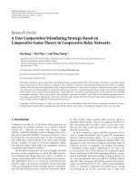
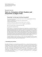
Figure 4: Outage probability versus number of antennas M and
NFCO ε.
impedance matrix. Assume perfect arrival angles, the beam
pattern is given by
A
=
N
n=−N
exp {−jnπ sinθ}
N
m=−N
C
n,m
exp {jmπ sinψ},
(30)
where C
n,m
is the (n, m)th element of the matrix C given in
(29), and the normalized beamforming gain can be obtained
by
G(θ, ψ)
=
|
AA
∗
|
M
2
. (31)
Substitute (31) into (2) , the modified α and B can be ob-
tained.
5. NUMERICAL RESULTS
The numerical investigation of the outage probability for a
reverse link MC-CDMA wireless cellular system with either
ideal beamforming or imperfect beamforming in the pres-
ence of CFO is given in this section. The spreading gain
L (or total number of subcarriers) for each user is set to
L
= 32. There are total K = 16 active users in the system.
The Nakagami-m channel fading is assumed over each sub-
carrier for all users. The required SINR threshold γ
0
is set to
6 dB. The signal-to-noise ratio (SNR) is defined as
SNR
=
LST
b
N
0
. (32)
The actual beam pattern is used for the desired user, while for
the interference users, the simplified beam pattern described
in Section 2.2 is used.
X. Hu and Y D. Yao 7
10
−7
10
−6
10
−5
10
−4
10
−3
10
−2
10
−1
10
0
Outage probability
0481216
20
SNR (dB)
M
= 1
M
= 3
M
= 5
M
= 7
M
= 9
L
= 32, K = 16
ε
= 0.1
γ
0
= 6dB
m
= 1
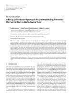
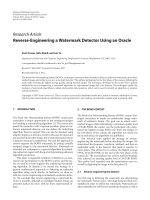
Figure 5: Outage probability versus SNR and number of antennas
M.
From Figure 4 to Figure 6, the outage probability is eval-
uatedwhenperfectbeamformingisassumedattheBS.
Figure 4 shows the effect of receive beamforming on the out-
age probability for reverse link MC-CDMA systems when
CFO is present. The Nakagami fading parameter m is set
to 1; SNR is assumed to be 10 dB. It can be observed from
Figure 4 that the outage probability improves significantly as
the number of receive antenna elements increases. The beam-
forming technique has brought a noticeable benefit for the
system performance. The larger the number of receive an-
tenna elements, the lower the outage probability of the sys-
tem. It is also seen from Figure 4 that the beamforming plays
an important role in mitigating the impact of the CFO. The
outage probability is approximately 0.1% when the NCFO
ε
= 0 and the number of antenna elements M = 3. When the
CFO increases to 30%, the outage probability deteriorates to
4%, which could be improved to 0.1% through the use of a
larger number of antenna elements M
= 7. This illustrates
the significant benefit of using the beamforming technique.
Figure 5 presents the outage probability versus SNR with
different number of receive antenna elements. The NCFO
ε and Nakagami fading parameter m are set to 0.1 and 1,
respectively. We observe that as SNR increases, the outage
probability decreases gradually. It can be seen from Figure 5
that the outage probability remains at a very high level no
matter how much SNR increases when the system does not
employ beamforming (the number of receive antennas M
=
1). This is due to the fact that the MUI contributes most of
the impairments to the system in this situation, and there
is no beamforming technique to mitigate the MUI. Hence it
is difficult to achieve the required SINR threshold γ
0
.How-
ever, when beamforming is used (M>1), it will combat the
MUI efficiently; as a result, the outage probability decreases
greatly.
10
−10
10
−8
10
−6
10
−4
10
−2
10
0
Outage probability
13579
Number of antennas M
m
= 1/2
m
= 1
m
= 2
m
= 3
L
= 32, K = 16
SNR
= 10 dB
γ
0
= 6dB
ε
= 0.1
Figure 6: Outage probability versus number of antennas M and
Nakagami m.
10
−6
10
−5
10
−4
10
−3
10
−2
10
−1
Outage probability
3456789
Number of antennas M
Δ
= 3/4Δ
max
Δ = 1/2Δ
max
Δ = 1/4Δ
max
Δ = 0(idealBF)
L
= 32, K = 16
ε
= 0.1
SNR
= 10 dB
γ
0
= 6dB
m
= 1
Figure 7: Outage probability with DOA estimation errors. Δ is the
standard deviation of uniformly distributed DOA estimation errors.
M is the number of antennas.
Figure 6 gives the outage probability under different Nak-
agami fading parameter m. Again, the SNR is set to 10 dB.
The figure shows that the outage probability decreases as the
parameter m increases. That is because that the better chan-
nel environment the system experiences, the larger the pa-
rameter m. Better channel conditions definitely improve the
system performance.
From Figure 7 to Figure 9, we investigate the impact of
beamforming impairments on the outage probability of the
system.
8 EURASIP Journal on Wireless Communications and Networking
10
−6
10
−5
10
−4
10
−3
10
−2
Outage probability
3456789
Number of antennas M
δ
= 6
◦
δ = 3
◦
δ = 1
◦
δ = 0(idealBF)
L
= 32, K = 16
ε
= 0.1
SNR
= 10 dB
γ
0
= 6dB
m
= 1
Figure 8: Outage probability with angle spreads. δ is the standard
deviation of uniformaly distributed angle spreads. M is the number
of antennas.
10
−6
10
−5
10
−4
10
−3
10
−2
Outage probability
3456789
Number of antennas M
With mutual coupling
Ideal BF
L
= 32, K = 16
ε
= 0.1
SNR
= 10 dB
γ
0
= 6dB
m
= 1
Figure 9: Outage probability with mutual coupling. M is the num-
ber of antennas.
In the following, a small CFO is assumed in the sys-
tem, that is, ε
= 0.1; the SNR is set to 10 dB and all users
experience Nakagami fading (m
= 1) over each subcarrier.
Figure 7 shows the effect of DOA estimation errors. The DOA
error is assumed to follow a uniform distribution with a stan-
dard deviation Δ,andΔ
max
is given in (27). It can be seen
from Figure 7 that the DOA estimation error does not im-
pact much on the outage probability when the error is within
the half null-to-null beam width (Δ
≤ (1/2)Δ
max
). When a
larger DOA estimation error is present, that is, the case of
Δ
≥ (3/4)Δ
max
in Figure 7, it leads to a significant increase of
the outage probability.
Figure 8 plots the outage probability when different an-
gle spreads are present in the system. The angle spread is as-
sumed to follow a uniform distribution with a standard devi-
ation δ. We observe that the outage probability does not vary
much when δ is small, that is, δ<3
◦
.However,anoticeable
deterioration of the outage probability can be seen if the an-
gle spread is large, that is the case of δ
= 6
◦
in Figure 8.
Figure 9 illustrates the impact of the mutual coupling
among antenna elements on the outage probability. From
Figure 9, only a very small change of the outage probability is
observed when the mutual coupling exists in the system. This
is because the distance between adjacent antenna elements is
λ/2 which is large enough to eliminate any noticeable cou-
pling.
6. CONCLUSION
The outage probability of reverse link MC-CDMA systems
with beamforming in the presence of CFO over Nakagami
fading channels is evaluated in this paper. A simplified beam-
forming model is utilized to reduce the complexity of the
analysis. A closed-form expression of the outage probabil-
ity is obtained to examine the effect of CFO and beamform-
ing. First, the outage probability is evaluated when perfect
beamforming is assumed. It can be concluded that the outage
probability improves significantly as the number of antenna
elements increases; second, the outage probability is investi-
gated when different types of beamforming impairments are
present in the system. It is seen that small DOA estimation er-
rors and angle spreads have only a slight impact on the outage
probability of the system; however, as those impairments be-
come large, the outage probability deteriorates significantly.
Also it is observed that the outage probability changes very
slightly when there is mutual coupling in the antenna array.
ACKNOWLEDGMENT
This work has been supported in part by NSF through Grants
CNS-0452235 and CNS-0435297.
REFERENCES
[1] R. Prasad, CDMA for Wireless Personal Communications,
Artech House, Norwood, Mass, USA, 1996.
[2] A.J.Viterbi,CDMA: Principles of Spread Spectrum Communi-
cation, Addison-Wesley, Redwood City, Calif, USA, 1995.
[3] K. Fazel and S. Kaiser, Multi-Carr ier and Spread Spectrum Sys-
tems, Wiley, New York, NY, USA, 2003.
[4] H. Krim and M. Viberg, “Two decades of array signal process-
ing research: the parametric approach,” IEEE Signal Processing
Magazine, vol. 13, no. 4, pp. 67–94, 1996.
[5] A. J. Paulraj and C. B. Papadias, “Space-time processing for
wireless communications,” IEEE Signal Processing Magazine,
vol. 14, no. 6, pp. 49–83, 1997.
[6] G. J. Foschini, “Layered space-time architecture for wireless
communication in a fading environment when using multi-
element antennas,” Bell Labs Technical Journal, vol. 1, no. 2,
pp. 41–59, 1996.
[7] J. H. Winters, “Smart antennas for wireless systems,” IEEE Per-
sonal Communications, vol. 5, no. 1, pp. 23–27, 1998.
X. Hu and Y D. Yao 9
[8] S. Hara and R. Prasad, “Overview of multicarrier CDMA,”
IEEE Communications Magazine, vol. 35, no. 12, pp. 126–133,
1997.
[9] X. Gui and T. S. Ng, “Performance of asychrounous orthog-
onal multicarrier CDMA system in frequency selective fading
channel,” IEEE Transactions on Communications, vol. 47, no. 7,
pp. 1084–1091, 1999.
[10] X. Hu and Y. H. Chew, “A new approach to study the ef-
fect of carrier frequency offset on the BER performance
of asynchronous MC-CDMA systems,” in Proceedings of the
IEEE Wireless Communications and Networking Conference
(WCNC ’05), vol. 1, pp. 177–182, Orleans, La, USA, March
2005.
[11] X. Hu and Y. H. Chew, “On the performance and capacity of
an asynchronous space-time block-coded MC-CDMA system
in the presence of carrier frequency offset,” IEEE Transactions
on Vehicular Technology, vol. 53, no. 5, pp. 1327–1340, 2004.
[12] Q. Shi and M. Latva-Aho, “Effect of frequency offset on the
performance of asynchronous MC-CDMA systems in a corre-
lated Rayleigh fading channel,” in Proceedings of the Interna-
tional Conferences on Info-Tech and Info-Net (ICII ’01), vol. 2,
pp. 448–452, Beijing, China, October-November 2001.
[13] J. Jang and K. B. Lee, “Effects of frequency offset on
MC/CDMA system performance,” IEEE Communications Let-
ters, vol. 3, no. 7, pp. 196–198, 1999.
[14] Y. Chen and E. S. Sousa, “Outage probability analysis of a
MC-DS-CDMA system with variable repetition code rate and
spreading factor,” IEEE Journal on Selected Areas in Communi-
cations, vol. 24, no. 6, pp. 1236–1243, 2006.
[15] J. Y. Kim, “Outage probability of a multicarrier DS/CDMA sys-
tem with adaptive antenna array,” in Proceedings of the 52nd
IEEE Vehicular Technology Conference (VTC ’00), vol. 6, pp.
2906–2910, Boston, Mass, USA, September 2000.
[16] H. L. Van Trees, OptimumArrayProcessing:PartIVofDetec-
tion, Estimation, and Modulation Theory,Wiley,NewYork,NY,
USA, 2002.
[17] J. C. Liberti and T. S. Rappaport, Smart Antennas for Wireless
Communications: IS-95 and Third Ge neration CDMA Applica-
tions, Prentice-Hall, Englewood Cliffs, NJ, USA, 1999.
[18] J. Yu, Y D. Yao, A. F. Molisch, and J. Zhang, “Performance
evaluation of CDMA reverse links with imperfect beamform-
ing in a multicell environment using a simplified beamform-
ing model,” IEEE Transactions on Vehicular Technology, vol. 55,
no. 3, pp. 1019–1031, 2006.
[19] S. Haykin, Adaptive Filter Theory, Prentice-Hall, Englewood
Cliffs, NJ, USA, 3rd edition, 1986.
[20] A. F. Naguib, A. J. Paulraj, and T. Kailath, “Capacity improve-
ment with base-station antenna arrays in cellular CDMA,”
IEEE Transactions on Vehicular Technology,vol.43,no.3,part
2, pp. 691–698, 1994.
[21] U. Spagnolini, “A simplified model for probability of error in
DS CDMA systems with adaptive antenna arrays,” in Proceed-
ings of the IEEE International Conference on Communications
(ICC ’01), vol. 7, pp. 2271–2275, Helsinki, Finland, June 2001.
[22] M. Abramowitz and I. A. Stegun, Handbook of Mathematical
Functions, Dover, New York, NY, USA, 1972.
[23] I. S. Gradshteyn and I. M. Ryzhik, Table of Integrals, Series and
Products
, Academic Press, New York, NY, USA, 1980.
[24] P. Pajusco, “Experimental characterization of DOA at the base
station in rural and urban area,” in Proceedings of the 48th IEEE
Vehicular Technology Conference (VTC ’98), vol. 2, pp. 993–
997, Ottawa, Ontario, Canada, May 1998.
[25]M.Toeltsch,J.Laurila,K.Kalliola,A.F.Molisch,P.
Vainikainen, and E. Bonek, “Statistical characterization of ur-
ban spatial radio channels,” IEEE Journal on Selected Areas in
Communications, vol. 20, no. 3, pp. 539–549, 2002.
[26] T. Svantesson, “Antennas and propagation from a signal pro-
cessing perspective,” Ph.D. dissertation, Department of Signals
and Systems, Chalmers University of Technology, Gothen-
burg, Sweden, 2001.
[27] C. Balanis, Antenna Theory, Analysis and Design,Wiley,New
York, NY, USA, 2nd edition, 1997.