Báo cáo hóa học: " Research Article Interference Robust Transmission for the Downlink of an OFDM-Based Mobile Communications " pptx
Bạn đang xem bản rút gọn của tài liệu. Xem và tải ngay bản đầy đủ của tài liệu tại đây (1.02 MB, 14 trang )
Hindawi Publishing Corporation
EURASIP Journal on Wireless Communications and Networking
Volume 2008, Article ID 549371, 14 pages
doi:10.1155/2008/549371
Research Article
Inter ference Robust Transmission for the Downlink of
an OFDM-Based Mobile Communications System
Markus Konrad and Wolfgang Gerstacker
Institute of Mobile Communications, University of Erlangen-Nuremberg, Cauerstrasse 7, 91058 Erlangen, Germany
Correspondence should be addressed to Markus Konrad,
Received 27 April 2007; Revised 24 August 2007; Accepted 17 November 2007
Recommended by Luc Vandendorpe
Radio networks for future mobile communications systems, for example, 3GPP Long-Term Evolution (LTE), are likely to use an
orthogonal frequency division multiplexing- (OFDM-) based air interface in the downlink with a frequency reuse factor of one
to avoid frequency planning. Therefore, system capacity is limited by interference, which is particularly crucial for mobile ter-
minals with a single receive antenna. Nevertheless, next generation mobile communications systems aim at increasing downlink
throughput. In this paper, a single antenna interference cancellation (SAIC) algorithm is introduced for amplitude-shift keying
(ASK) modulation schemes in combination with bit-interleaved coded OFDM. By using such a transmission strategy, high gains
in comparison to a conventional OFDM transmission with quadrature amplitude modulation (QAM) can be achieved. The supe-
rior performance of the novel scheme is confirmed by an analytical bit-error probability (BEP) analysis of the SAIC receiver for a
single interferer, Rayleigh fading, and uncoded transmission. For the practically more relevant multiple interferer case we present
an adaptive least-mean-square (LMS) and an adaptive recursive least-squares (RLS) SAIC algorithm. We show that in particular
the RLS approach enables a good tradeoff between performance and complexity and is robust even to multiple interferers.
Copyright © 2008 M. Konrad and W. Gerstacker. This is an open access article distributed under the Creative Commons
Attribution License, which permits unrestricted use, distribution, and reproduction in any medium, provided the original work is
properly cited.
1. INTRODUCTION
Next generation mobile communications air interfaces, such
as 3GPP Long-Term Evolution (LTE) [1]orWiMax[2],
will employ orthogonal frequency division multiplexing
(OFDM) for transmission in the downlink. In order to avoid
frequency planning, a frequency reuse factor of one is en-
visaged for 3GPP LTE. Hence, with conventional receivers
without interference suppression capabilities, transmission is
possible only with relatively low data rates due to the result-
ing capacity limitation which contradicts the desire for high
downlink data rates.
For this reason, interference cancellation and suppression
has been and is a vivid area of research, and various con-
tributions for OFDM transmission have already been made.
In [3], interference suppression for synchronous and asyn-
chronous cochannel interferers is studied. At the receiver
side, an adaptive antenna array is employed which performs
minimum mean-squared error (MMSE) diversity combining
in order to exploit receive diversity. The approach introduced
in [4] aims at optimizing the receive signal-to-interference-
plus-noise ratio (SINR). The authors show that SINR based
maximum ratio combining yields significant gains with re-
spect to pure SNR optimization. Receive antenna diversity
based interference suppression is also proposed in [5], where
the presented solution is suited for time-invariant and time-
variant channels. This is due to a two-stage structure com-
prising spatial diversity and constraint-based beamforming.
In [6, 7], transmit and receive antenna diversity have been
exploited in MIMO OFDM systems. Cochannel interference
is suppressed in order to increase the user data rates and
the number of users who can access the system. In [6] the
focus lies on spatial multiplexing whereas in [7] solutions
for space-time-coded MIMO systems involving beamform-
ing are developed.
OFDM transmission with real-valued data symbols has
been studied in [8], where an equalizer for suppression of
intercarrier interference resulting from the time-variance of
the mobile radio channel has been introduced which exploits
the fact that the transmitted symbols are one-dimensional.
2 EURASIP Journal on Wireless Communications and Networking
However, cochannel interference and channel coding were
not taken into account.
As indicated above, multiple receive antennas are advan-
tageous for cancellation of cochannel interference. However,
due to cost and size limitations it is still a challenge to include
more than one transmit antenna into a mobile terminal.
Therefore, single antenna interference cancellation (SAIC)
algorithms have received significant attention in academia
and industry in recent years, especially for transmission with
single-carrier modulation (cf. [9–11]). The benefits of SAIC
were analyzed in [12] for GSM radio networks, and it has
been shown that GSM network capacity can be dramatically
improved by SAIC.
In this paper, we propose an SAIC algorithm for OFDM
transmission, extending the approach in [13–15], referred
to as mono-interference cancellation (MIC) to the down-
link of an OFDM based air interface. For this scheme, real-
valued amplitude-shift keying (ASK) modulation is used and
additional channel coding is considered. Independent com-
plex filtering with subsequent projection for interference re-
moval is applied to each OFDM subcarrier. We present a
zero-forcing (ZF) approach, the analytical MMSE solution,
and also adaptive approaches which are based on the least-
mean-square (LMS) and the recursive least-squares (RLS) al-
gorithm, respectively. It turns out that the RLS algorithm is
particularly suited for practical implementation.
In principle, real-valued ASK modulation has the draw-
back of being less power efficient than a corresponding com-
plex quadrature amplitude modulation (QAM) constellation
as the constellation points cannot be packed as densely in
the complex plane as for QAM. However, since only one real
dimension is used for data transmission, additional degrees
of freedom are available which can be exploited for inter-
ference suppression at the receiver. In [16]itwasdemon-
strated that transmission with real-valued data symbols can
lead to a higher spectral efficiency for DS-CDMA transmis-
sion than using a complex symbol alphabet. In [17]widely
linear equalization and blind channel identification using a
minimum energy output energy adaptation algorithm is pro-
posed for OFDM transmission impaired by narrowband in-
terference.
We show that the improved possibilities for interference
suppression in case of real-valued symbols more than com-
pensate for the loss in power efficiency and even signifi-
cant gains are possible in an interference limited environ-
ment with respect to a conventional OFDM scheme em-
ploying coded QAM modulation with the same spectral effi-
ciency. Performance of a QAM scheme in principle could be
enhanced by successive interference cancellation (SIC) [18].
However, due to the presence of multiple interferers in prac-
tical applications, SIC alone could not achieve an acceptable
performance and hence, it would have to be combined with
successive decoding [18]. Unfortunately, because desired sig-
nal and interferers are usually not frame aligned and the code
laws of the interferers are not known in general, successive
decoding is not applicable here.
In principle, optimum soft-output multiuser detection
(MUD) without considering the code laws is a further al-
ternative. However, in [18], Verd
´
u showed that the compu-
tational complexity of an optimum multiuser detector in-
creases exponentially with the number of users. In addition,
the complexity of such a detector increases with the size of
the modulation alphabet, which becomes particularly crucial
for 16QAM and 64QAM transmission. Thus, MUD seems
to be prohibitively complex for mobile terminals, assuming
spectrally efficient OFDM transmission.
For these reasons, we do not consider interference sup-
pression for conventional QAM transmission as this can be
accomplished only by MUD or SIC for a single receive an-
tenna. Instead, we use a low-complexity suboptimum detec-
tor equipped with a ZF equalizer for each subcarrier. For
equalizer design, perfect channel knowledge is assumed.
For both schemes convolutional coding (CC) and bit-
wise interleaving over time and frequency are employed and
comparisons are made for equal spectral efficiency. For the
QAM scheme a lower code rate R
c
is applied in comparison
to the ASK scheme in order to obtain the same spectral ef-
ficiency. Since for QAM no interference cancellation is ap-
plied, a higher coding gain ensures reasonable, however, in
most cases inferior performance in comparison to the ASK
scheme, as will be demonstrated.
In order to support the simulation results for the adaptive
SAIC algorithm for coded and bit-interleaved OFDM trans-
mission, we provide an analysis of the raw bit-error proba-
bility (BEP) of both schemes before channel decoding. The
results confirm that significant gains are possible for M-ary
ASK transmission in comparison to M
2
-ary QAM transmis-
sion.
The remainder of the paper is organized as follows. In
Section 2, the system model is introduced. In Section 3,we
present an SAIC scheme for OFDM. A ZF- and an MMSE-
SAIC approach are introduced, respectively, and adaptive
SAIC solutions are presented. Section 4 provides a theoreti-
calanalysisofsubcarrierBEPofZF-SAICforuncodedtrans-
mission over a Rayleigh fading channel and a single inter-
ferer. Simulation results are presented in Section 5 for the
multiple interferer case applying both analytical and adaptive
MMSE SAIC approaches in an LTE-related scenario for M-
ary ASK transmission. A comparison to conventional QAM
transmission with ZF equalization is provided which again
shows the superior performance of ASK combined with
SAIC. Section 6 summarizes the paper and presents our con-
clusions.
2. SYSTEM MODEL
Since only a single receive antenna is available, the class of
interference cancellation algorithms exploiting receive diver-
sity is excluded here. In the considered scenario a mobile
terminal is impaired by additive white Gaussian noise and J
cochannel interferers representing surrounding base stations.
The interferers are present on all subcarriers of the desired
signal. The transmission is protected by CC with code rate
R
c
and block interleaving with interleaving depth I
B
. Subse-
quent linear modulation for the OFDM subcarriers uses real-
valued coefficients (e.g., M-ary ASK modulation; M:sizeof
M. Konrad and W. Gerstacker 3
modulation alphabet) for both desired and interferer signals
which are assumed to employ the same modulation alphabet.
For OFDM transmission, a rectangular pulse shaping fil-
terisappliedandaguardinterval(GI)ofsufficient dura-
tion is used such that intersymbol interference (ISI) can be
avoided. The GI contains a cyclic extension of the trans-
mit sequence such that the convolution of the discrete-time
channel impulse response and the transmit sequence be-
comes cyclic at the receiver side after elimination of the
GI and can be represented by a multiplication in discrete-
frequency domain [19]. Thus, subcarrier μ of the ith re-
ceive signal block represented in discrete-frequency domain
is given by
R
i
[μ] = H
i
[μ]A
i
[μ]+
J
j=1
G
j,i
[μ]B
j,i
[μ]+N
i
[μ], (1)
where i is the OFDM symbol index and j is the interferer in-
dex, 1
≤ j ≤ J. The discrete-time channel impulse responses
comprising the effects of transmit filtering, the mobile chan-
nel, and receive filtering for the desired signal and the in-
terferer signals are assumed to be mutually independent and
constant during the transmission of a data frame but chang-
ing randomly from frame to frame (block fading). The corre-
sponding discrete-frequency responses are H
i
[μ]andG
j,i
[μ]
for the desired signal and the interferers, respectively. A
i
[μ]
and B
j,i
[μ] denote the i.i.d. real-valued data symbols of de-
sired user and interferers, respectively, at symbol time i and
subcarrier frequency μ. The receiver noise is modeled by a
white Gaussian process with one-sided noise power density
N
0
and is represented in frequency domain by N
i
[μ]. For (1)
it has been assumed that the OFDM symbols of desired sig-
nal and interferers are time-aligned, that is, the network is
synchronous, as, for example, in [20]. Furthermore, perfect
frequency synchronization has been assumed.
3. INTERFERENCE SUPPRESSION FOR
OFDM TRANSMISSION
In [13–15] an approach for SAIC was introduced for applica-
tion in the GSM system where the interfering signal is elim-
inated by complex filtering and subsequent projection of the
filtered signal onto an arbitrary nonzero complex number c
for the case of a single interferer. In the presence of multi-
ple interferers, the filter coefficients are optimized such that
the variance of the difference between the signal after projec-
tion and the desired signal is minimized, that is, an MMSE
criterion is applied, guaranteeing interference suppression
at minimum noise enhancement. The algorithm has been
derived for flat fading as well as frequency-selective fading
channels. As in an OFDM system the channel can be consid-
ered as flat for each subcarrier, the variant of the algorithm
for flat fading is directly applicable to each subcarrier, and
the required filter order of the complex filter P
i
[μ]forsub-
carrier μ is zero. We denote the real-valued output signal of
projection by Y
i
[μ]. The error signal, consisting of noise and
residual interference, is given by
E
i
[μ] = Y
i
[μ] −A
i
[μ] = P
c
P
i
[μ]R
i
[μ]
−
A
i
[μ],
(2)
where P
c
{x} denotes projection of x onto an arbitrary
nonzero complex number c and is given by
P
c
{x}=
Re
x·c
∗
|c|
2
(3)
(cf. [13–15]), and we also introduce c
⊥
= Im{c}−jRe{c}
and note that the inner product of c and c
⊥
when interpreted
as two-dimensional vectors is 0 (Re
{·}: real part of a complex
number; Im
{·}: imaginary part of a complex number).
3.1. ZF solution
Under the presence of only a single interferer, that is, J
=
1, and assuming perfect channel knowledge we can apply a
ZF solution for P
i
[μ]. The projection of the filtered received
signal R
i
[μ] can be expressed as [15]
P
c
P
i
[μ]R
i
[μ]
=
Re
P
i
[μ]H
i
[μ]c
∗
|c|
2
A
i
[μ]
+
Re
P
i
[μ]G
1,i
[μ]c
∗
|c|
2
B
1,i
[μ]
+
Re
P
i
[μ]N
i
[μ]c
∗
|c|
2
.
(4)
Without loss of generality, c
= 1 is assumed for the following.
Choosing P
i
[μ]as
P
i
[μ] = c
⊥
G
∗
1,i
[μ]
G
1,i
[μ]
=−
j·
G
∗
1,i
[μ]
G
1,i
[μ]
,(5)
and using c
⊥
c
∗
=−j results in
P
c
P
i
[μ]R
i
[μ]
=
Re
G
∗
1,i
[μ]H
i
[μ]c
⊥
c
∗
G
1,i
[μ]
A
i
[μ]
+
Re
G
∗
1,i
[μ]G
1,i
[μ]c
⊥
c
∗
G
1,i
[μ]
B
1,i
[μ]
+
Re
G
∗
1,i
[μ]N
i
[μ]c
⊥
c
∗
G
1,i
[μ]
=
Im
G
∗
1,i
[μ]·H
i
[μ]
G
1,i
[μ]
A
i
[μ]
+
N
i
[μ] =
H
i
[μ]A
i
[μ]+
N
i
[μ],
(6)
such that the interferer is perfectly cancelled. The effective
channel coefficient for the desired signal after filtering and
projection is given by
H
i
[μ] = Im
G
∗
1,i
[μ]
G
1,i
[μ]
H
i
[μ]
. (7)
3.2. MMSE solution
For an MMSE approach, which is more suitable to suppress
multiple interferers, the associated cost function is defined as
J
P
i
[μ]
E
P
c
P
i
[μ]·R
i
[μ]
−A
i
[μ]
2
,(8)
4 EURASIP Journal on Wireless Communications and Networking
where E {·} is the expectation operator. Exploiting the fact
that the cost function is convex we determine its minimum
via the zeros of its derivative,
∂
∂P
∗
[μ]
J
P
i
[μ]
!
= 0. (9)
This results in
∂J
P
i
[μ]
∂P
∗
i
[μ]
= Φ
RR
[μ]P
i
[μ]+Φ
R
∗
R
[μ]P
∗
i
[μ] −2 ϕ
AR
[μ]
!
= 0,
(10)
where (
·)
∗
denotes complex conjugation. The expressions in
(10)aredefinedby
Φ
RR
[μ] = E
R
i
[μ]R
∗
i
[μ]
=
σ
2
a
·
H
i
[μ]
2
+
J
j=1
σ
2
j
·
G
j,i
[μ]
2
+2σ
2
n
,
(11)
ϕ
AR
[μ] = E
A
i
[μ]R
∗
i
[μ]
=
σ
2
a
·H
∗
i
[μ], (12)
Φ
R
∗
R
[μ] = E
R
∗
i
[μ]
2
=
σ
2
a
·
H
∗
i
[μ]
2
+
J
j=1
σ
2
j
·
G
∗
j,i
[μ]
2
,
(13)
where σ
2
a
and σ
2
j
(1 ≤ j ≤ J)denotethevariancesofde-
sired signal and of interferer signal j,respectively,andσ
2
n
is the variance of the inphase component of the rotation-
ally symmetric noise N
i
[μ]. The total interference power is
σ
2
I
=
J
j
=1
σ
2
j
. By splitting (10) into real and imaginary part
and after straightforward calculations we obtain the solution
for the MMSE filter P
i
[μ]:
P
i
[μ] = 2
ϕ
AR
[μ]Φ
RR
[μ] −ϕ
∗
AR
[μ]Φ
R
∗
R
[μ]
Φ
2
RR
[μ]+
Φ
R
∗
R
[μ]
2
. (14)
Assuming that only a single interferer is present (J
= 1) and
σ
2
n
→0, we can simplify (14) and obtain
P
i
[μ] =−j·
G
∗
1,i
[μ]
Im
H
i
[μ]G
∗
1,i
[μ]
, (15)
which is equivalent to the ZF solution presented in (5)apart
from a scaling factor. The derivation of this result is provided
in Appendix A. Hence, when noise is negligible the projec-
tion of the filtered received signal according to (6) results in
Re
−
j·
H
i
[μ]G
∗
1,i
[μ]
Im
H
i
[μ]G
∗
1,i
[μ]
A
i
[μ]
+Re
−
j·
G
1,i
[μ]G
∗
1,i
[μ]
Im
H
i
[μ]G
∗
1,i
[μ]
B
1,i
[μ] = A
i
[μ],
(16)
where the interferer has been perfectly cancelled as for the ZF
solution.
3.3. Adaptive approaches
In order to determine filter coefficients approximating the
MMSE solution, several OFDM training symbols A
i
[·]are
required for LMS and RLS algorithm, respectively. However,
only the desired user’s training symbols have to be known,
and the algorithm performs blind adaptation with respect to
interference.
(1) LMS algorithm
After the training period, the filter coefficients P
i
[μ]arefixed
and used for complex filtering in the current transmission
frame, assuming that the channel is time-invariant during
each frame.
The filter update equation for the projection filter is
given, for example, in [21]. Using the normalized version of
the LMS algorithm to allow for an adaptive LMS step size
parameter we obtain the following update rule for the pro-
jection filter coefficients P
i+1
[μ]:
P
i+1
[μ] = P
i
[μ]+
ρ
M
x
[μ]+
E
i
[μ]·R
∗
i
[μ], (17)
where M
x
[μ] is the expected power of the filter input signal
R
i
[μ],
M
x
[μ] = E
R
i
[μ]
2
. (18)
The parameter
ρ has to be chosen as 0 < ρ<2 to guarantee a
convergence of the algorithm. The variable
1 is a small
real number required for regularization.
The convergence of the LMS algorithm is quite slow and
therefore the algorithm does not seem suitable for practical
applications. In contrast, the recursive least-squares (RLS) al-
gorithm exhibits better performance in terms of convergence
speed. Furthermore, the misadjustment [21] of the LMS al-
gorithm is dependent on the dominant-to-residual interfer-
ence (DIR) ratio and is generally larger than that of the RLS
algorithm.
(2) RLS algorithm
The major advantage of the RLS algorithm is an order
of magnitude faster convergence than that of the LMS al-
gorithm [21] such that also time-variant channels can be
tracked. This renders the proposed cancellation scheme suit-
able for practical implementation. As for the LMS algorithm,
each subcarrier is treated independently and, hence, com-
plexity scales linearly with the number of subcarriers. The
input vector of the algorithm per subcarrier μ is defined as
U
i
[μ] =
Re
R
i
[μ]
−
Im
R
i
[μ]
T
, (19)
where (
·)
T
denotes transposition. The a priori error signal
of the RLS algorithm is defined as the difference of desired
signal and the output of projection of the filtered received
signal,
E
i
[μ] = A
i
[μ] −Re
P
i−1
[μ]R
i
[μ]
=
A
i
[μ] −U
T
i
[μ]P
i−1
[μ].
(20)
M. Konrad and W. Gerstacker 5
With definition of variables U
i
[μ]andE
i
[μ], the RLS algo-
rithm can be applied in the form given in [21].
4. ANALYSIS OF RAW BEP OF ZF-SAIC AND
COMPARISON TO STANDARD QAM TRANSMISSION
In order to prove that significant gains can be obtained by the
SAIC receiver in conjunction with real-valued modulation
we first provide a closed-form analysis for uncoded trans-
mission. The results also characterize performance of coded
transmission before channel decoding (raw BEP). A single
OFDM subcarrier with Rayleigh fading channel coefficient
H
i
[μ] and the presence of a single interferer using also real-
valued modulation with channel coefficient G
1,i
[μ]areas-
sumed. The aim of this section is to provide a fundamen-
tal understanding of the performance of the SAIC scheme by
deriving the BEP and comparing it to that of corresponding
QAM schemes. The number of interferers is J
= 1 and the
interference power is given by σ
2
I
.
The channel power of the desired user before filtering and
projection is given by ξ
=|H
i
[μ]|
2
, where the probability
density function (pdf) of ξ is f
ξ
(ξ) = e
−ξ
.Theaveragereceive
signal power before filtering is given by σ
2
a
·E {|H
i
[μ]|
2
} and
normalized to one, σ
2
a
= E {|H
i
[μ]|
2
}=1, where σ
2
a
is the
variance of the desired signal.
In the following, we omit the subcarrier index μ, inter-
ferer index j, and OFDM symbol index i for simplicity in
H
i
[μ] as well as in the interferer channel coefficient G
1,i
[μ]
and assume that both channel coefficients are known. Ex-
panding the expression in (7) for the effective channel co-
efficient
H after ZF-SAIC projection results in
H =|H|·sin
arg {H}−arg {G}
=|H|·sin(ϕ), (21)
where ϕ
= arg {H}−arg {G} is uniformly distributed with
f
ϕ
(ϕ) =
⎧
⎪
⎨
⎪
⎩
1
2π
,0
≤ ϕ<2π,
0, else
(22)
(arg
{·}:argumentoperator).Withξ =|H|
2
and ν = sin
2
(ϕ)
the received power after SAIC is a function of the random
variables ξ and ν,
p(ν, ξ)
= ν·ξ, (23)
which are mutually independent. The pdf of ν can be derived
from the pdf of ϕ.Withν
= sin
2
(ϕ)weobtain
dν
dϕ
= 2·sin ϕcos ϕ. (24)
By using
1
2π
dϕ
=
1
2π
·
1
2·sin ϕcos ϕ
dν, (25)
0
0.5
1
1.5
2
2.5
3
f
p
(p), f
ξ
(ξ)
00.511.522.53
p
Analytical, f
ξ
(ξ)
Simulation, f
p
(p)
Analytical, f
p
(p)
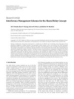
Figure 1: Pdfs f
ξ
(ξ)andf
p
(p) of received power before and after
ZF-SAIC, respectively.
taking into account that ϕ(ν) is quadruple valued [22], using
√
ν =|sin ϕ| and |cos ϕ|=
1 −sin
2
(ϕ), we obtain
f
ν
(ν) =
⎧
⎪
⎨
⎪
⎩
1
π
·
1
ν(1 −ν)
,for0< ν < 1,
0, else.
(26)
The joint pdf f
ν,ξ
(ν, ξ) = f
ν
(ν)·f
ξ
(ξ) is needed to calculate
the pdf of the product p(ν, ξ)
= ν·ξ resulting in
f
p
(p) =
1
0
f
ν,ξ
ν,
p
ν
1
ν
dν
=
1
0
1
ν(1 −ν)
·
e
−p/ν
πν
dν
=
1
√
π
e
−p
√
p
.
(27)
According to Figure 1, the receive power after SAIC is
more likely to attain small values than before SAIC, as can
be easily seen by comparing with the pdf f
ξ
(ξ) representing
the receive power before SAIC.
4.1. Average SINR gain for 2ASK transmission
Assuming perfect channel knowledge, the SAIC scheme re-
moves the interferer perfectly, such that the average receive
SINR after SAIC is given by
SINR
=
σ
2
a
·E{p}
σ
2
n
. (28)
The average SINR before interference cancellation for ASK
transmission is
SINR
0
=
σ
2
a
σ
2
n
+ σ
2
I
. (29)
6 EURASIP Journal on Wireless Communications and Networking
−5
0
5
10
15
20
25
30
G (dB)
0 5 10 15 20 25 30
SNR
CIR
= 0dB
CIR
= 10 dB
CIR
= 20 dB
CIR
= 30 dB
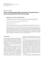
Figure 2: SINR gain of ZF-SAIC for ASK transmission versus SNR
for different CIRs. A single interferer has been assumed.
The average receive power after SAIC can be calculated to
E
{p}=
∞
0
p·f
p
(p) dp =
1
2
. (30)
Hence, the SAIC scheme causes a 3 dB loss in receive power
on average, but completely cancels the interference. In or-
der to benefit from SAIC for ASK transmission the following
condition has to be met:
SINR
≥ SINR
0
, (31)
or
σ
2
a
2σ
2
n
≥
σ
2
a
σ
2
n
+ σ
2
I
.
(32)
Hence, the proposed ZF-SAIC scheme is beneficial as long as
σ
2
I
≥ σ
2
n
. (33)
This is always fulfilled in the interference limited case, which
we consider here. The gain in average SINR of the SAIC
scheme compared to a standard ASK receiver can be ex-
pressed as
G
= 10·log
10
σ
2
I
+ σ
2
n
2σ
2
n
[dB] (34)
andisdepictedinFigure 2, where the SNR is defined as
σ
2
a
/σ
2
n
. Figure 2 demonstrates that large SINR gains are pos-
sible by using SAIC in comparison to conventional zero-
forcing reception, particularly for high SNRs.
4.2. Closed-form BEP calculation for ZF-SAIC
using M-ary ASK for transmission over
Rayleigh fading channels
In the following, we derive closed form expressions for BEP
after SAIC for M-ary ASK transmission. In particular, since
2ASK, 4ASK, and 8ASK are considered in the simulations of
Section 5 we provide the corresponding analytical formulas
here.
In the following, the average subcarrier
E
b
/N
0
is abbrevi-
ated by x, and the instantaneous subcarrier E
b
/N
0
is abbrevi-
ated by y. Using (27), considering that y
= p·x, and applying
a variable transform results in the pdf of y which is given by
f
y
(y) =
1
√
π·x
·
e
−(y/x)
√
y
. (35)
For the following BEP calculations the definition
G(M)
=
6log
2
M
2
M
2
−1
(36)
is needed, with G(2)
= 1, G(4) = 2/5, and G(8) = 1/7. The
BEP for 2ASK for fixed instantaneous E
b
/N
0
is given by [23]
P
2ASK
b
(y) =
1
2
erfc
G(2)y
=
1
2
erfc
y
. (37)
For 4ASK the following BEP is obtained [24]:
P
4ASK
b
(y) =
2
Mlog
2
M
·
3
2
erfc
G(4)y
+erfc
3·
G(4)y
−
1
2
erfc
5·
G(4)y
=
3
8
erfc
2
5
y
+
1
4
erfc
18
5
y
−
1
8
erfc
10y
.
(38)
Finally, BEP for 8ASK reads [24]
P
8ASK
b
(y) =
7
24
erfc
1
7
y
+
1
4
erfc
9
7
y
−
1
24
erfc
25
7
y
+
1
24
erfc
81
7
y
−
1
24
erfc
169
7
y
.
(39)
The average raw BEP of the ZF-SAIC algorithm can be writ-
ten as
BEP
=
∞
0
P
b
(y) f
y
(y)dy. (40)
Using Craig’s formula [25],
erfc
√
x
=
2
π
π/2
0
exp
−
x
sin
2
(θ)
dθ, (41)
the BEP for M-ary ASK can be written as the sum of integrals
over the same type of function. We need the identity
∞
0
erfc
αG(M)y
f
y
(y)dy
=
1
√
πx
2
π
∞
0
π/2
0
exp
−
αG(M)y
sin
2
θ
×
exp
−
y
x
y
−(1/2)
dθ dy
=
1
2
1 −
2
π
arctan
αG(M)x − 1
2
αG(M)x
,
(42)
M. Konrad and W. Gerstacker 7
where α ∈ R
+
.TheproofisgiveninAppendix B. Using (42),
it is straightforward to show that the BEP of 2ASK after SAIC
can be written as
P
2ASK
b
(x) =
1
4
−
1
2π
arctan
x − 1
2
√
x
. (43)
The closed-form solution for the BEP of 4ASK is
P
4ASK
b
(x) =
3
16
1 −
2
π
arctan
(2/5)x −1
2
(2/5)x
+
1
8
1 −
2
π
arctan
(18/5)x −1
2
(18/5)x
−
1
16
1 −
2
π
arctan
10x − 1
2
√
10x
,
(44)
where (38) and again (42)havebeenused,andfor8ASKwe
obtain
P
8ASK
b
(x) =
7
48
1 −
2
π
arctan
(1/7)x −1
2
(1/7)x
+
1
8
1 −
2
π
arctan
(9/7)x −1
2
(9/7)x
−
1
48
1 −
2
π
arctan
(25/7)x −1
2
(25/7)x
+
1
48
1 −
2
π
arctan
(81/7)x −1
2
(81/7)x
−
1
48
1 −
2
π
arctan
(169/7)x −1
2
(169/7)x
(45)
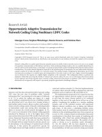
with (39)and(42). BEP after SAIC per subcarrier is depicted
in Figure 3 versus the subcarrier
E
b
/N
0
.
In the following, we develop a low SNR approximation of
BEP for 2ASK. With the trigonometric equivalence of [26]
arctan γ
= arcsin
⎛
⎝
γ
1+γ
2
⎞
⎠
, (46)
we can rewrite
arctan
x − 1
2
√
x
=
arcsin
⎛
⎝
(x − 1)/2
√
x
1+
(x − 1)/2
√
x
2
⎞
⎠
=
arcsin
x − 1
x +1
.
(47)
Thus, the alternative expression
P
2ASK
b
E
b
N
0
=
1
4
−
1
2π
arcsin
E
b
/N
0
−1
E
b
/N
0
+1
(48)
follows from (43)and(47). For
E
b
/N
0
≈ 1 we can approxi-
mate the BEP by using
arcsin (y)
≈ y for |y|1, (49)
resulting in
P
2ASK
b
E
b
N
0
≈
1
4
−
1
2π
·
E
b
/N
0
−1
E
b
/N
0
+1
, (50)
10
−2
10
−1
10
0
BEP
0 5 10 15 20 25 30
E
b
/N
0
(dB)
2ASK, BEP analytical
4ASK, BEP analytical
8ASK, BEP analytical
Figure 3: BEP after ZF-SAIC versus E
b
/N
0
for 2ASK, 4ASK, and
8ASK. A single interferer has been assumed.
or
P
2ASK
b
E
b
N
0
≈
1
4
−
1
2π
·
E
b
/N
0
−1
2
E
b
/N
0
, (51)
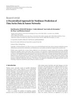
exploiting the equivalence in (47). The exact BEP, the simu-
lated raw BER, and both low SNR BEP approximations are
shown in Figure 4 for a carrier-to-interference ratio (CIR)
of 10 dB, where CIR
= σ
2
a
/σ
2
I
. Both approximations are in
good agreement for
E
b
/N
0
between −5 dB and 5 dB. Analyti-
cal and simulation results for BEP of 2ASK after SAIC match
perfectly.
In the following, we determine the diversity order for M-
ary ASK, that is, the slope of the BEP curve for
E
b
/N
0
→∞
in a double-logarithmic representation. For M-ary ASK the
average BEP can be expressed as
P
MASK
b
E
b
N
0
=
i
b
i
·t
i
E
b
N
0
,
(52)
where
t
i
E
b
N
0
=
1 −
2
π
·arctan
⎛
⎝
c
i
E
b
/N
0
−1
2
c
i
E
b
/N
0
⎞
⎠
.
(53)
For 2ASK, 4ASK, and 8ASK, respectively, the values of b
i
and
c
i
can be extracted from the analytical formulas for BEP given
in (43), (44), and (45).
For determining the diversity order we first consider
t
i
(E
b
/N
0
)for(E
b
/N
0
)→∞. After substituting E
b
/N
0
by e
λ
we
obtain
t
i
(λ) = 1 −
2
π
arctan
c
i
e
λ
−1
2
c
i
e
λ
=
1 −
2
π
arctan
sinh
ln c
i
+ λ
2
.
(54)
8 EURASIP Journal on Wireless Communications and Networking
10
−2
10
−1
10
0
BER
−10 −50 5101520
E
b
/N
0
(dB)
2ASK, BER simulated
2ASK, BEP analytical
2ASK, BEP low SNR approximation (arctan)
2ASK, BEP low SNR approximation (arcsin)
Figure 4: Analytical BEP, simulated BER, and low SNR BEP ap-
proximations versus subcarrier
E
b
/N
0
for ZF-SAIC. A single inter-
ferer has been assumed.
Subsequently, we have to calculate the limit of the derivative
of the natural logarithm of t
i
(λ)withrespecttoλ for λ→∞.
With
ln
t
i
(λ)
= ln
1 −
2
π
arctan
sinh
ln c
i
+ λ
2
,
(55)
we obtain
d
dλ
ln
t
i
(λ
) =−
1
π
·
a(λ)
cosh
ln c
i
+ λ
/2
−1
1 −
2
π
arctan
sinh
(ln c
i
+ λ
/2
b(λ)
.
(56)
Because lim
λ→∞
a(λ) = 0 and lim
λ→∞
b(λ) = 0wehaveto
apply L’Hospitale’s rule in order to find the derivative. With
a
(λ) =−
1
2
·
tanh
ln c
i
+ λ
/2
cosh
ln c
i
+ λ
/2
,
b
(λ)|=−
1
π
·
1
cosh
ln c
i
+ λ
/2
,
(57)
the diversity order of t
i
(E
b
/N
0
)is
−lim
λ→∞
d
dλ
ln
t
i
(λ)
=
1
2
∀i,
(58)
which is independent of the constant c
i
.Wecanexpressthe
limit of t
i
(λ)forλ→∞ as
lim
λ→∞
t
i
(λ) = lim
λ→∞
exp
d
dλ
ln
t
i
(λ)
dλ
=
lim
λ→∞
exp
−
1
2
λ +
c
i
=
e
c
i
·e
−(1/2)λ
,
(59)
where
c
i
is an integration constant. By using (52)and(59)we
obtain the limit of the average BEP for λ
→∞ as
lim
λ→∞
P
MASK
b
(λ) =
i
b
i
·lim
λ→∞
t
i
(λ) =
i
b
i
·e
c
i
·e
−(1/2)λ
= C·e
−(1/2)λ
,
(60)
where
C
=
i
b
i
·e
c
i
, C ∈ R
+
.
(61)
The diversity order for M-ary ASK is then given by
−lim
λ→∞
d
dλ
ln
P
MASK
b
(λ)
=−
lim
λ→∞
d
dλ
ln
C·e
−(1/2)λ
=
1
2
(62)
for all ASK constellations considered in this paper.
4.3. M
2
-ary QAM transmission over a Rayleigh fading
channel with a single interferer
In the following, we assume that the interference can be
modeled by a Gaussian random process with average vari-
ance σ
2
I
. The average CIR is defined by the ratio of the power
of the useful signal and that of the interferer signal, and
both powers are exponentially distributed with mean values
σ
2
a
= 1andσ
2
I
= 1/CIR, respectively. The effective subcar-
rier E
b
/N
0
for a given instantaneous CIR value, denoted by
CIR
inst
,is
E
b
N
0
eff
=
1
1/
E
b
/N
0
+
log
2
M/CIR
inst
. (63)
Closed-form expressions for the BEP in dependence on the
subcarrier
E
b
/N
0
for M
2
-ary QAM (4QAM, 16QAM, and
64QAM) transmission over a Rayleigh fading channel are
provided in Appendix C. Using these, we can determine the
average BEP of QAM numerically for a given average CIR
by inserting (E
b
/N
0
)
eff
in the respective formulas and averag-
ing over CIR
inst
. In Figures 5–7, the BEP performance versus
E
b
/N
0
of M
2
-ary QAM and M-ary ASK transmission is com-
pared for M
= 2, 4, and 8, respectively. M-ary ASK trans-
mission with SAIC performs worse than M
2
-ary QAM trans-
mission for infinite CIR due to the reduced diversity degree
of 1/2. However, for finite CIRs ASK transmission in com-
bination with SAIC outperforms QAM transmission as long
as the subcarrier
E
b
/N
0
is above a certain threshold depend-
ing on CIR. Furthermore, the ASK BEP curves do not exhibit
bit-error floors, in contrast to the QAM curves. For example,
for a CIR of 10 dB, the proposed ASK scheme using SAIC
outperforms the corresponding QAM transmission if
E
b
/N
0
exceeds values of 25, 20, and 15 dB, respectively, for M = 2, 4,
and 8 (cf. Figures 5–7). This analysis clearly shows that large
gains can be obtained in an interference limited scenario by
using the proposed scheme.
5. SIMULATION RESULTS FOR ADAPTIVE SAIC
AND MULTIPLE INTERFERERS
The key parameters for the numerical results shown in this
section are summarized in Tab le 1 . A carrier frequency of
M. Konrad and W. Gerstacker 9
10
−4
10
−3
10
−2
10
−1
10
0
BER
−10 −5 0 5 1015202530
E
b
/N
0
(dB)
4QAM, CIR
=∞dB
4QAM, CIR
= 20 dB
4QAM, CIR
= 10 dB
4QAM, CIR
= 0dB
2ASK, ZF SAIC
Figure 5: BEP for 2ASK and 4QAM transmission versus subcarrier
E
b
/N
0
for different CIRs. A single interferer has been assumed.
10
−4
10
−3
10
−2
10
−1
10
0
BER
−10 −5 0 5 1015202530
E
b
/N
0
(dB)
16QAM, CIR
=∞dB
16QAM, CIR
= 20 dB
16QAM, CIR
= 10 dB
16QAM, CIR
= 0dB
4ASK, ZF SAIC
Figure 6: BEP for 4ASK and 16QAM transmission versus subcarrier
E
b
/N
0
for different CIRs. A single interferer has been assumed.
2 GHz is assumed, and the number of used OFDM subcarri-
ers was set to 512. All subcarriers are impaired by cochannel
interference and additive white Gaussian noise. In the fol-
lowing,
E
b
denotes the average receive energy per bit of the
desired signal. The carrier-to-interference ratio is given by
CIR
= C/I
t
,whereC and I
t
are the average receive power
of the desired signal and of the total interference, respec-
tively. In order to model the interference structure of a cellu-
lar network, J
= 3 cochannel interferers are considered. One
of the interferers dominates and has power I
d
, whereas the
other, residual interferers have equal average powers I
2
and
10
−4
10
−3
10
−2
10
−1
10
0
BER
−10 −50 5 1015202530
E
b
/N
0
(dB)
64QAM, CIR
=∞dB
64QAM, CIR
= 20 dB
64QAM, CIR
= 10 dB
64QAM, CIR
= 0dB
8ASK, ZF SAIC
Figure 7: BEP for 8ASK and 64QAM transmission versus subcarrier
E
b
/N
0
for different CIRs. A single interferer has been assumed.
Table 1: Simulation parameters.
Parameter
Valu e
Number of subcarriers
512
System bandwidth B
7.68 MHz
Code rates R
c
2/3, 1/2, 1/3, 1/4
Interleaving depth I
B
32 bits
Channel model
Typical urban [27]
Maximum channel excess delay
τ
max
= 7 μs
Number of interferers J
3
OFDM sample spacing
T
s
= 130.2ns
OFDM symbol duration
T
= 512·T
s
= 66.67 μs
Length of guard interval T
G
0.25·T
Number of training symbols for the
LMS algorithm
210
Normalized LMS step size parameter
ρ
0.2
Number of training symbols for the
RLS algorithm
21
RLS forgetting factor λ [21]
0.99
Number of simulated channels
10
4
I
3
. The total power of the residual interference is I
r
= I
2
+ I
3
,
and I
t
= I
d
+ I
r
. The dominant-to-residual-interference ratio
(DIR) is defined as I
d
/I
r
.
The considered discrete-time channel impulse responses
of desired signal and interferers have mutually uncorrelated
Rayleigh fading taps with average tap powers according to an
exponential power delay profile which is determined from
the continuous typical urban power delay profile given in
[27], P(τ)
= e
−τ/τ
0
for 0 ≤ τ ≤ τ
max
= 7 μsandP(τ) = 0
else, where τ
0
= 1 μs, by sampling with a sample spacing of
T
s
= 130.2 ns. A block fading model is adopted with random
10 EURASIP Journal on Wireless Communications and Networking
10
−4
10
−3
10
−2
10
−1
10
0
BER
0 5 10 15 20 25 30
E
b
/N
0
(dB)
16QAM, R
c
= 1/4, R = 1 bps/Hz, CIR = 8 dB, DIR = 0dB
4ASK, R
c
= 1/2, R = 1 bps/Hz, CIR = 8 dB, DIR = 0dB
64QAM, R
c
= 1/4, R = 1.5 bps/Hz, CIR = 11 dB, DIR = 0dB
8ASK, R
c
= 1/2, R = 1.5 bps/Hz, CIR = 11 dB, DIR = 0dB
64QAM, R
c
= 1/3, R = 2 bps/Hz, CIR = 15 dB, DIR = 0dB
8ASK, R
c
= 2/3, R = 2 bps/Hz, CIR = 15 dB, DIR = 0dB
64QAM, R
c
= 1/3, R = 2 bps/Hz, CIR = 12 dB, DIR = 5dB
8ASK, R
c
= 2/3, R = 2 bps/Hz, CIR = 12 dB, DIR = 5dB
Figure 8: BER after channel decoding versus E
b
/N
0
for different
transmission schemes and interference conditions.
changes from frame to frame. Each frame consists of training
blocks and data blocks. Each block comprises 7 OFDM sym-
bols, and channel coding and interleaving are performed on
each block.
The choice of simulation parameters used in this paper
was to a large extent inspired by the 3GPP LTE standard [1].
The sampling rate of 1/T
s
= 7.68 MHz, the number of 512
subcarriers, the OFDM subcarrier bandwidth of 15 kHz, and
the number of 7 OFDM symbols per block, respectively, con-
form with the downlink FDD specifications of the LTE stan-
dard. Furthermore, we confine the QAM constellation size
to a maximum of M
2
= 64 as in [1] and the correspond-
ing ASK constellation size to M
= 8. However, instead of
leaving a large part of the spectrum unused as proposed in
[1], we use 512 modulated subcarriers per OFDM symbol,
which results in a total system bandwidth of B
= 512·15 kHz
= 7.68 MHz. The impulse response length of the typical ur-
ban channel τ
max
= 7 μs exceeds the duration of the short
guard interval as standardized in LTE for unicast transmis-
sion. For that reason we choose the long guard interval which
has a length of 25% of the OFDM symbol duration in order
to exclude intersymbol interference. Furthermore, we prefer
convolutional coding to turbo coding to maintain a low re-
ceiver complexity. We use entire OFDM symbols as training
symbols for the algorithms proposed in this paper as opposed
to reference symbols as indicated in the LTE standard.
The performance results for the proposed scheme with
ASK transmission and SAIC are compared with results for
QAM transmission with ZF equalization. In this case, the re-
ceiver has perfect channel knowledge. For both schemes, in-
10
−4
10
−3
10
−2
10
−1
10
0
BER
−15 −10 −50 51015
CIR (dB)
DIR
=−5dB,an
DIR
= 0dB,an
DIR
= 5dB,an
DIR
= 10 dB, an
DIR
= 15 dB, an
DIR
= 20 dB, an
DIR
=−5dB,RLS
DIR
= 0dB,RLS
DIR
= 5dB,RLS
DIR
= 10 dB, RLS
DIR
= 15 dB, RLS
DIR
= 20 dB, RLS
DIR
= 0dB,LMS
DIR
= 10 dB, LMS
QAM DIR
= 0dB
Figure 9: BER after channel decoding versus CIR for varying DIR.
4ASK with R
c
= 0.5 and 16QAM with R
c
= 0.25, R = 1 bit/s/Hz.
“an” stands for the analytical MMSE solution.
terleaving with interleaving depth I
B
and CC with constraint
length 9 is applied. Furthermore, in order to provide a fair
comparison, QAM transmission is stronger protected by CC
than ASK in order to obtain the same spectral efficiency R
(bit/s/Hz).
5.1. Performance under presence of
noise and interference
In the following, we compare the performance of the SAIC
approach using the RLS algorithm and that of the conven-
tional QAM transmission scheme for low DIR values of 0 and
5 dB, respectively. The CIR has been chosen such that both
receivers yield block-error rates (BLER) below 50%. Figure 8
illustrates results for the BER after channel decoding, which
indicate that for DIR
= 0dBand highE
b
/N
0
the proposed
scheme performs better than the conventional QAM scheme
except for the case of transmission with a spectral efficiency
of 2.0 bit/s/Hz. This case corresponds to 8ASK transmission
with code rate R
c
= 2/3, and its performance is inferior
to that of the conventional scheme with 64QAM transmis-
sion and R
c
= 1/3 in terms of BER for DIR = 0dB, but
still acceptable. The reason for this behavior is that for ASK
M. Konrad and W. Gerstacker 11
10
−3
10
−2
10
−1
10
0
BLER
−15 −10 −50 51015
CIR (dB)
DIR
=−5dB,an
DIR
= 0dB,an
DIR
= 5dB,an
DIR
= 10 dB, an
DIR
= 15 dB, an
DIR
= 20 dB, an
DIR
=−5dB,RLS
DIR
= 0dB,RLS
DIR
= 5dB,RLS
DIR
= 10 dB, RLS
DIR
= 15 dB, RLS
DIR
= 20 dB, RLS
DIR
= 0dB,LMS
DIR
= 10 dB, LMS
QAM DIR
= 0dB
Figure 10: BLER after channel decoding versus CIR for varying
DIR. 4ASK with R
c
= 0.5 and 16QAM with R
c
= 0.25, R =
1 bit/s/Hz. “an” stands for the analytical MMSE solution.
transmission the coding gain is not high enough in this case.
However, also for this modulation and coding scenario an in-
crease in DIR boosts the performance of our approach. For a
DIR of at least 5 dB the conventional scheme is outperformed
for high
E
b
/N
0
by the proposed scheme at the same spectral
efficiency as illustrated in Figure 8. Please note that this be-
havior in principle reflects the results of Section 4,whereit
was shown that the raw BEP of the proposed scheme is supe-
rior for moderate-to-high
E
b
/N
0
.
5.2. Performance in the interference limited case
In the following, simulation results for an interference lim-
ited scenario with J
= 3 interferers as previously are pre-
sented.
E
b
/N
0
= 30 dB is valid. BER and block-error rate
(BLER) results are shown for the analytical MMSE solution
(cf. (14)) and the adaptive solution using LMS and RLS al-
gorithm, respectively, in Figures 9 to 12. BER results are only
provided for selected cases in addition to the BLER results,
which have a higher significance with respect to system per-
formance. Results for the conventional scheme are shown
only for a DIR of 0 dB. This is justified because performance
10
−3
10
−2
10
−1
10
0
BLER
−15 −10 −50 51015
CIR (dB)
DIR
=−5dB,an
DIR
= 0dB,an
DIR
= 5dB,an
DIR
= 10 dB, an
DIR
= 15 dB, an
DIR
= 20 dB, an
DIR
=−5dB,RLS
DIR
= 0dB,RLS
DIR
= 5dB,RLS
DIR
= 10 dB, RLS
DIR
= 15 dB, RLS
DIR
= 20 dB, RLS
DIR
= 0dB,LMS
DIR
= 10 dB, LMS
QAM DIR
= 0dB
Figure 11: BLER after channel decoding versus CIR for varying
DIR. 8ASK with R
c
= 0.5 and 64QAM with R
c
= 0.25, R =
1.5 bit/s/Hz. “an” stands for the analytical MMSE solution.
of QAM transmission is approximately independent of DIR
and only depends on CIR.
From Figures 9 to 12 we observe that the proposed
scheme performs better and better with increasing DIR and
yields significant gains. The proposed scheme in combina-
tion with CC and interleaving outperforms the correspond-
ing conventional QAM transmission scheme for all DIRs for
4ASK and 8ASK transmission with R
c
= 1/2. For 8ASK
with CC with R
c
= 2/3 the proposed scheme requires a
DIR
≥ 5 dB to perform superior to conventional transmis-
sion which is represented by 16QAM with R
c
= 1/2and
64QAM with R
c
= 1/3 (cf. Figure 12).ADIRof5dBisrealis-
tic in practice assuming low shadowing correlation of differ-
ent base stations. As a result of a higher diversity gain due to
coding the slope of the QAM BER/BLER curves is higher than
that of the corresponding curves for ASK modulation, where
a higher code rate was used to obtain the same spectral effi-
ciency. Nevertheless, ASK outperforms QAM if a certain, rea-
sonably low DIR threshold is exceeded. For a DIR of 20dB,
that is, a highly dominant cochannel interferer is present,
a gain of approximately 14 dB can be observed for 4ASK
and 8ASK with R
c
= 1/2 with respect to the conventional
12 EURASIP Journal on Wireless Communications and Networking
10
−3
10
−2
10
−1
10
0
BLER
−15 −10 −50 51015
CIR (dB)
DIR
=−5dB,an
DIR
= 0dB,an
DIR
= 5dB,an
DIR
= 10 dB, an
DIR
= 15 dB, an
DIR
= 20 dB, an
DIR
=−5dB,RLS
DIR
= 0dB,RLS
DIR
= 5dB,RLS
DIR
= 10 dB, RLS
DIR
= 15 dB, RLS
DIR
= 20 dB, RLS
DIR
= 0dB,LMS
DIR
= 10 dB, LMS
16QAM DIR
= 0dB
64QAM DIR
= 0dB
Figure 12: BLER versus CIR for varying DIR. 8ASK with R
c
= 0.67,
16QAM with R
c
= 0.5, and 64QAM with R
c
= 0.33, R = 2 bit/s/Hz.
“an” stands for the analytical MMSE solution.
transmission schemes and a gain of approximately 10 dB re-
sults for 8ASK with R
c
= 2/3.
Further analysis has shown that a training length of 21
OFDM symbols is sufficient in order to obtain essentially
the same performance with the adaptive RLS scheme as with
the analytical MMSE solution for filter P
i
[μ]. This is due to
the fact that the excess error induced by the RLS algorithm
becomes small after a few training symbols already because
of the adopted filter length of one, resulting in almost coin-
ciding curves for both solutions. For the LMS algorithm the
training length has been chosen about 10 times higher than
for the RLS algorithm and still a performance loss in the or-
der of approximately 1 dB for DIRs of 0 to 10 dB can be ob-
served from Figures 9 to 12. Therefore, the LMS algorithm is
impractical for scenarios with mobile users resulting in time-
varying impulse responses. Further results not shown here
demonstrate that the adaptive RLS scheme is also robust to
imperfect frequency synchronization causing frequency off-
sets.
In summary, the performance results for the conven-
tionalQAMschemewithaDIRof0dBinFigures9 to 11
are always inferior to that of the proposed scheme for spec-
tral efficiencies of 1.0and1.5 bit/s/Hz. The results for a spec-
tral efficiency of 2.0 bit/s/Hz of Figure 12 show that the pro-
posed scheme requires a DIR of at least 5dB to outperform
the conventional QAM scheme, which has been already ob-
served from Figure 8.
6. CONCLUSIONS
A novel strategy for downlink OFDM transmission under
presence of severe cochannel interference was presented,
which combines coded real-valued ASK modulation and sin-
gle antenna interference cancellation. Our scheme enables
high downlink data rates already at low CIR values and is
capable of exploiting increasing DIRs contrary to the con-
ventional OFDM transmission scheme using QAM modu-
lation. A comparison to QAM transmission has shown that
for all modulation and coding schemes studied in this paper,
the novel scheme is superior with respect to BER/BLER after
channel decoding for DIRs of at least 5 dB for the same spec-
tral efficiency R. For higher values of DIR, gains up to 14 dB
have been noticed. The superior performance of the pro-
posed scheme is confirmed by the given closed-form analysis
of the raw BEP. Therefore, by exploiting the additional de-
grees of freedom gained by using real-valued modulation we
can more than compensate for the loss in power efficiency
of ASK and enable high user data rates with a blind interfer-
ence suppression scheme which does not require any explicit
knowledge about the interferers and is moderate in terms
of computational complexity. In future work, an analytical
evaluation of BER/BLER after channel coding will be made,
based on the presented closed-form raw BEP results.
APPENDICES
A. MMSE SOLUTION FOR A SINGLE INTERFERER
AT HIGH E
b
/N
0
The MMSE solution for the projection filter P
i
[μ]isgivenby
P
i
[μ] = 2
ϕ
AR
[μ]Φ
RR
[μ] −ϕ
∗
AR
[μ]Φ
R
∗
R
[μ]
Φ
2
RR
[μ]+
Φ
R
∗
R
[μ]
2
. (A.1)
With J
= 1andσ
2
n
→0 we can simplify Φ
RR
[μ] (cf. (11)) and
obtain
Φ
RR
[μ] = E
R
i
[μ]R
∗
i
[μ]
=
σ
2
a
·
H
i
[μ]
2
+ σ
2
I
·
G
1,i
[μ]
2
.
(A.2)
Expanding (A.1) by inserting the expressions for Φ
RR
[μ],
ϕ
AR
[μ], and Φ
R
∗
R
[μ], respectively, results in
P
i
[μ] = 2·
σ
2
a
·H
∗
i
[μ]·
σ
2
a
·
H
i
[μ]
2
+ σ
2
I
·
G
1,i
[μ]
2
K[μ] −K
[μ]
−
σ
2
a
·H
i
[μ]·
σ
2
a
·
H
∗
i
[μ]
2
+ σ
2
I
·
G
∗
1,i
[μ]
2
K[μ] −K
[μ]
,
(A.3)
M. Konrad and W. Gerstacker 13
where
K[μ]
=
σ
2
a
·
H
i
[μ]
2
+ σ
2
I
·
G
1,i
[μ]
2
2
,
K
[μ] =
σ
2
a
·
H
∗
i
[μ]
2
+ σ
2
I
·
G
∗
1,i
[μ]
2
2
.
(A.4)
We can simplify this expression and obtain
P
i
[μ] =−2
σ
2
a
·σ
2
I
·G
∗
1,i
[μ]
σ
2
a
·σ
2
I
·
H
∗
i
[μ]G
1,i
[μ] −H
i
[μ]G
∗
1,i
[μ]
H
∗
i
[μ]G
1,i
[μ] −H
i
[μ]G
∗
1,i
[μ]
2
=−
G
∗
1,i
[μ]
(1/2)
H
∗
i
[μ]G
1,i
[μ] −H
i
[μ]G
∗
1,i
[μ]
=−
j·
G
∗
1,i
[μ]
Im
H
i
[μ]G
∗
1,i
[μ]
.
(A.5)
B. THE SOLUTION TO THE DOUBLE INTEGRAL
We aim at solving the following double integral:
1
√
πx
2
π
π/2
0
∞
0
exp (−(αG(M)y/sin
2
(θ)))·exp (−(y/x))
√
y
dydθ,
(B.1)
where α
∈ R
+
. The inner integral has the solution [26]
∞
0
exp
−
αG(M)y/sin
2
(θ)
·exp
−(y/x)
√
y
dy
=
Γ(1/2)
1/x +
αG(M)/sin
2
(θ)
=
√
π
√
x sinθ
αG(M)x +sin
2
θ
for 0
≤ θ ≤
π
2
,
(B.2)
where Γ(1/2)
=
√
π has been used [28]. Subsequent outer
integration yields
π/2
0
√
x sinθ
αG(M)x +sin
2
θ
dθ
=
1
2
√
x arctan
1
2
αG(M)x +1
−2cos
2
θ
cos θ
1+αG(M)x − cos
2
θ
π/2
0
=
1
2
√
x
π
2
−arctan
αG(M)x − 1
2
αG(M)x
,
(B.3)
which can be proved by means of differentiation of the sec-
ond expression. Hence, the solution to the complete double
integral is given by
1
2
1 −
2
π
arctan
αG(M)x − 1
2
αG(M)x
. (B.4)
C. BEP OF QAM TRANSMISSION OVER
A RAYLEIGH FADING CHANNEL
The exact bit-error probabilities for transmission over the
AWGN channel with 4QAM, 16QAM, and 64QAM modu-
lation, respectively, can be expressed as [24]
P
4QAM
b
(y) =
1
2
·erfc
G(4)y
,
P
16QAM
b
(y) =
3
8
·erfc
G(16)y
+
1
4
·erfc
9
G(16)y
−
1
8
·erfc
25
G(16)y
,
P
64QAM
b
(y) =
7
24
·erfc
G(64)y
+
1
4
·erfc
9
G(64)y
−
1
24
·erfc
25
G(64)y
+
1
24
·erfc
81
G(64)y
−
1
24
·erfc
169
G(64)y
,
(C.1)
where
y is the instantaneous subcarrier E
b
/N
0
and
G(M) =
(6log
2
M/4(M − 1)) (
G(4) = 1,
G(16) = 2/5,
G(64) = 1/7).
The expected BEP for transmission over a Rayleigh fading
channel versus x
= E
b
/N
0
is therefore
P
b
(x) =
∞
0
P
b
(y) f
y
(y) dy. (C.2)
Please note that the M
2
-ary QAM superscripts have been
omitted for simplicity, here. This integral can be solved in
closed form for all M
2
-ary QAM constellations. Using y =
ξ·x and f
ξ
(ξ) = e
−ξ
the pdf of y is expressed as
f
y
(y) =
e
−y/x
x
. (C.3)
Then, in order to determine the BEPs for M
2
-ary QAM trans-
mission over a Rayleigh fading channel the following identity
is needed:
∞
0
erfc
α
G(M)x
e
−y/x
x
d
y
=
2
πx
π/2
0
∞
0
exp
−
y
α
G(M)x +sin
2
θ
xsin
2
θ
dydθ
=
2
π
π/2
0
sin
2
θ
α
G(M)x +sin
2
θ
dθ
= 1 −
α
G(M)x
1+α
G(M)x
,
(C.4)
where the solution to the inner integral can be found in [26]
and the solution for the outer integral is implicitly stated in
14 EURASIP Journal on Wireless Communications and Networking
[19]. Therefore, the average BEP for 4QAM, 16QAM, and
64QAM, respectively, is
P
4QAM
b
(x) =
1
2
1 −
x
1+x
,
P
16QAM
b
(x) =
3
8
1 −
(2/5)x
1+(2/5)x
+
1
4
1 −
(18/5)x
1+(18/5)x
−
1
8
1 −
10x
1+10x
,
P
64QAM
b
(x) =
7
24
1 −
(1/7)x
1+(1/7)x
+
1
4
1 −
(9/7)x
1+(9/7)x
−
1
24
1 −
(25/7)x
1+(25/7)x
+
1
24
1 −
(81/7)x
1+(81/7)x
−
1
24
1 −
(169/7)x
1 + (169/7)x
.
(C.5)
REFERENCES
[1] 3GPP, “Physical layer aspects for evolved utra (V7.1.0),” Tech.
Rep. TR 25.814, 3rd Generation Partnership Project (3GPP),
2006.
[2] IEEE Std 802.16e, “IEEE standard for local and metropoli-
tan area networks, part 16: air Interface for fixed and mobile
broadband wireless access systems,” Tech. Rep., IEEE, 2006.
[3] Y. Li and N. R. Sollenberger, “Adaptive antenna arrays for
OFDM systems with cochannel interference,” IEEE Transac-
tions on Communications, vol. 47, no. 2, pp. 217–229, 1999.
[4] B S. Seo, S G. Choi, and J S. Cha, “Maximum ratio com-
bining for OFDM systems with cochannel interference,” IEEE
Transactions on Consumer Electronics, vol. 52, no. 1, pp. 87–91,
2006.
[5] S. Kapoor, D. J. Marchok, and Y F. Huang, “Adaptive inter-
ference suppression in multiuser wireless OFDM systems us-
ing antenna arrays,” IEEE Transactions on Signal Processing,
vol. 47, no. 12, pp. 3381–3391, 1999.
[6] L. Giangaspero, L. Agarossi, G. Paltenghi, S. Okamura, M.
Okada, and S. Komaki, “Co-channel interference cancellation
based on MIMO OFDM systems,” IEEE Wireless Communica-
tions, vol. 9, no. 6, pp. 8–17, 2002.
[7] J. Li, K. B. Letaief, and Z. Cao, “Co-channel interference can-
cellation for space-time coded OFDM systems,” IEEE Trans-
actions on Wireless Communications, vol. 2, no. 1, pp. 41–49,
2003.
[8] P. Tan and N. C. Beaulieu, “An improved MMSE equalizer for
one-dimensional modulation OFDM systems,” in Proceedings
of the Vehicular Technology Conference (VTC ’05), pp. 157–160,
September 2005.
[9] P. Chevalier and F. Pipon, “New insights into optimal widely
linear array receivers for the demodulation of BPSK, MSK,
and GMSK signals corrupted by noncircular interferences—
application to SAIC,” IEEE Transactions on Signal Processing,
vol. 54, no. 3, pp. 870–883, 2006.
[10] H. Trigui and D. T. M. Slock, “Cochannel interference can-
cellation within the current GSM standard,” in Proceedings
of the International Conference on Personal Communications
(ICUPC ’98), 1998.
[11] M. Pukkila, G. P. Mattellini, and P. A. Ranta, “Cochannel inter-
ference suppression for constant modulus signals,” in Proceed-
ings of the IEEE International Conference on Communications,
vol. 5, pp. 2548–2552, 2004.
[12] A. Mostafa, R. Kobylinski, I. Kostanic, and M. Austin, “Sin-
gle Antenna Interference Cancellation (SAIC) for GSM net-
works,” in Proceedings of the IEEE Vehicular Technology Con-
ference (VTC ’04), vol. 2, pp. 1089–1093, October 2004.
[13] R. Meyer, W. H. Gerstacker, R. Schober, and J. B. Huber, “A sin-
gle antenna interference cancellation algorithm for GSM,” in
Proceedings of the IEEE Vehicular Technology Conference (VTC
’05), vol. 2, pp. 821–825, Stockholm, Sweden, May-June 2005.
[14] R. Meyer, W. Gerstacker, and R. Schober, “Method for
Cancelling Interference during TDMA Transmission and/or
FDMA Transmission,” International Patent Application
WO02/054660A1, PCT/EP01/15019 (granted), 2000.
[15] R. Meyer, W. H. Gerstacker, R. Schober, and J. B. Huber, “A sin-
gle antenna interference cancellation algorithm for increased
GSM capacity,” IEEE Transactions on Wireless Communica-
tions, vol. 5, no. 7, pp. 1616–1621, 2006.
[16] A. Lampe and M. Breiling, “Asymptotic analysis of widely
linear MMSE multiuser detection—complex vs. real modu-
lation,” in Proceedings of IEEE Information Theory Workshop
(ITW ’01), September 2001.
[17] D. Darsena, G. Gelli, L. Paura, and F. Verde, “Widely linear
equalization and blind channel identification for interference-
contaminated multicarrier systems,” IEEE Transactions on Sig-
nal Processing, vol. 53, no. 3, pp. 1163–1177, 2005.
[18] S. Verd
´
u, Multiuser Detection, Cambridge University Press,
New York, NY, USA, 1998.
[19] K. D. Kammeyer, Nachrichten
¨
ubertragung,Teubner,Stuttgart,
Germany, 3rd edition, 2004.
[20] R. Rebhan and J. Zander, “On the outage probability in sin-
gle frequency networks for digital broadcasting,” IEEE Trans-
actions on Broadcasting, vol. 39, no. 4, pp. 395–401, 1993.
[21] N. Benvenuto and G. Cherubini, Algorithms for Communica-
tions Systems and Their Applications,Wiley,NewYork,NY,
USA, 2002.
[22] J. Bendat and A. G. Persol, Random Data, Analysis and Mea-
surement Procedures, Wiley, New York, NY, USA, 1986.
[23] J. G. Proakis, Digital Communications, McGraw-Hill, Boston,
Mass, USA, 2001.
[24] K. Cho and D. Yoon, “On the general BER expression of one-
and two-dimensional amplitude modulations,” IEEE Transac-
tions on Communications, vol. 50, no. 7, pp. 1074–1080, 2002.
[25] C. Tellambura and A. Annamalai, “Derivation of Craig’s for-
mula for Gaussian probability function,” Electronics Letters,
vol. 35, no. 17, pp. 1424–1425, 1999.
[26] G. Grosche, V. Ziegler, and D. Ziegler, Taschenbuch der Math-
ematik, Verlag Harri Deutsch, Frankfurt, Germany, 1985.
[27] M. Failli, COST 207 Digital Land Mobile Radio Communica-
tions, Commission of the European Communities, 1989.
[28]T.K.MoonandW.C.Stirling,Mathematical Methods and
Algorithms for Signal Processing, Prentice-Hall, Upper Saddle
River, NJ, USA, 2000.