Báo cáo hóa học: " Research Article System-Platforms-Based SystemC TLM Design of Image Processing Chains for Embedded Applications" potx
Bạn đang xem bản rút gọn của tài liệu. Xem và tải ngay bản đầy đủ của tài liệu tại đây (929.48 KB, 14 trang )
Hindawi Publishing Corporation
EURASIP Journal on Embedded Systems
Volume 2007, Article ID 71043, 14 pages
doi:10.1155/2007/71043
Research Article
System-Platforms-Based SystemC TLM Design of Image
Processing Chains for Embedded Applications
Muhammad Omer Cheema,
1, 2
Lionel Lacassagne,
2
and Omar Hammami
1
1
EECS Department, Ecole Nationale Superieure de Techniques Avancees, 32 Boulevard Victor, 75739 Paris, France
2
Axis Department, University of Paris Sud, 91405 Orsay, France
Received 18 October 2006; Accepted 3 May 2007
Recommended by Paolo Lombardi
Intelligent vehicle design is a complex task which requires multidomains modeling and abstraction. Transaction-level modeling
(TLM) and component-based software development approaches accelerate the process of an embedded system design and simu-
lation and hence improve the overall productivity. On the other hand, system-level design languages facilitate the fast hardware
synthesis at behavioral level of abstraction. In this paper, we introduce an approach for hardware/software codesign of image pro-
cessing applications targeted towards intelligent vehicle that uses platform-based SystemC TLM and component-based software
design approaches along with HW synthesis using SystemC to accelerate system design and verification process. Our experiments
show the effectiveness of our methodology.
Copyright © 2007 Muhammad Omer Cheema et al. This is an open access article distributed under the Creative Commons
Attribution License, which permits unrestricted use, distribution, and reproduction in any medium, provided the original work is
properly cited.
1. INTRODUCTION
Embedded systems using image processing algorithms rep-
resent an important segment of today’s electronic industry.
New developments and research trends for intelligent vehi-
cles include image analysis, video-based lane estimation and
tracking for driver assistance, and intelligent cr uise control
applications [1–5]. While there has been a notable growth
in the use and application of these systems, the desig n pro-
cess has become a remarkably difficult problem due to the
increasing design complexity and shortening time to market
[6]. A lot of work is being done to propose the methodolo-
gies to accelerate automotive system design and verification
process based on multimodeling paradigm. This work has re-
sulted in a set of techniques to shorten the time consuming
steps in system design process. For example, transaction-level
modeling makes system simulation significantly faster than
the register transfer level. Platform-based design comes one
step forward and exploits the reusability of IP components
for complex embedded systems. Image processing chain us-
ing component-based modeling shortens the software de-
sign time. Behavioral synthesis techniques using system-level
design languages (SLDLs) accelerate the hardware realiza-
tion process. Based on these techniques, many tools have
been introduced for system-on-chip (SoC) designers that
allow them to make informed decisions early in the de-
sign process which can be the difference in getting prod-
ucts to market quicker. The ability to quickly evaluate the
cross-domain effects of desig n tradeoffsonperformance,
power, timing, and die size gives a huge advantage much ear-
lier than was ever achievable with traditional design tech-
niques.
While time to market is an important parameter for sys-
tem design, an even more important aspect of system de-
sign is to optimally utilize the existing techniques to meet the
computation requirements of image processing applications.
Classically, these optimization techniques have been intro-
duced a t microprocessor level by customizing the proces-
sors and generating digital signal processors, pipelining the
hardware to exploit instruction-level parallelism, vectorizing
techniques to exploit data-level parallelism, and so forth. In
system-level design era, more emphasis has been on the tech-
niques that are more concerned with interaction between
multiple processing elements instead of optimization of indi-
vidual processing elements, that is, heterogeneous MPSoCs.
HW/SW codesign is a key element in modern SoC design
techniques. In a traditional system design process, computa-
tion intensive elements are implemented in hardware which
results in the significant system speedup at the cost of in-
crease in hardware costs.
2 EURASIP Journal on Embedded Systems
MIPS
RAM
Value
0
20
40
60
80
100
120
MGT560
MPC533
MPC534
MPC535
MPC536
MPC555
MPC561
MPC562
MPC563
MPC564
MPC565
MPC566
Automotive microcontroller Freescale
(a)
JTAG
Burst
buffer
controller 2
DECRAM
(4 Kbytes)
4KbytesCALRAMB
4 Kbytes overlay
512 Kbytes
flash
512 Kbytes
flash
READI
L2U
32 Kbytes CALRAMA
28 Kbytes SRAM
no overlay
4 Kbytes overlay
USIU
TPU3 TPU3 TPU3
4Kbytes
DPTRAM
Tou
CAN
Tou
CAN
Tou
CAN
MIOS14
QADC64E
w/AMUX
QADC64E
w/AMUX
QSMCM QSMCM
UIMB
I/F
DLCMD2
IMB3
U-bus
E-bus
L-bus
6Kbytes
DPTRAM
PowerPC
core
+
FP
(b)
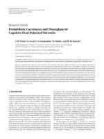
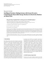
Figure 1: Freescale MPC controllers: (a) MIPS/embedded RAM, (b) MPC 565 block diagram.
In this paper, we propose an HW/SW codesign method-
ology that advocates the use of the following.
(i) Platfor m-based transaction-level modeling to acceler-
ate system-level design and verification.
(ii) Behavioral synthesis for fast hardware modeling.
(iii) Component-based SW development to accelerate soft-
ware design.
Using these techniques, we show that complex embedded
systems can be modeled and validated in short times while
providing satisfactory system performance.
Rest of the paper is organized as follows. Section 2
presents related work. Section 3 overviews the general ve-
hicle design methodology and establishes a direct link with
our proposal. Section 4 describes a very recent SystemC TLM
platform: the IBM PowerPC evaluation kit. Section 5 ex-
plains our system design methodology and Section 6 de-
scribes the experiment environment and results. Future work
and a proposed combined UML-SystemC TLM platform are
described in Section 7. Finally, Section 8 concludes.
2. RELATED WORK
When designing embedded applications for intelligent ve-
hicles a whole set of microcontrollers are available. An ex-
ample of such an offer comes from Freescale [7] with their
PowerPC-based microcontrollers (Figure 1).
However, although diverse in the MIPS and embedded
RAM these microcontrollers do not offer enough flexibility
to add specific hardware accelerators such as those required
by image processing applications. The PowerPC core of these
microcontrollers is not sufficient in this peripherals inten-
sive environment to exclusively support software computa-
tion intensive applications. It is then necessary to customize
these microcontrollers by adding additional resources while
keeping the general platform with its peripherals. A system-
design approach is needed. Our work is based on three differ-
ent aspects of system design. Although some work has been
done on each of these aspects at individual level, no effort has
been made to propose a complete HW/SW codesign flow that
gets benefit out of all these techniques to improve the system
productivity. In the following sections, we will present the
related work done on each of these domains. Transaction-
level modeling based on system-level design languages has
proven to be a fast and efficient way of system design [8–10].
It has been shown that simulation at this level is much faster
[8] than register transfer level (RTL) and makes it possible
for us to explore the system design space for HW/SW parti-
tioning and parameterization. The idea of transaction-level
modeling (TLM) is to provide in an early phase of the hard-
ware development transaction-level models of the hardware.
Based on this technique, a fast-enough simulation environ-
ment is the basis for the development of hardware and hard-
ware dependent software. The presumption is to run these
transaction-level models at several tens or some hundreds
of thousand transactions per second which should be fast-
enough for system-level modeling and verification. A lot of
work has been done on behavioral synthesis. With the evo-
lution of system-level design languages, the interest in effi-
cient hardware synthesis based on behavioral description of a
hardware module has also been visible. A few tools for behav-
ioral SystemC synthesis [11, 12] are available in the market.
Muhammad Omer Cheema et al. 3
Requirements
definition
Requirements
verification
Functional
verification
Functional
design
Architecture
design
Architecture
validation & test
System
integration & test
System integration
design
Component
design
Component
test
Tier 2
Figure 2: V design cycle.
For a system designer, behavioral system is very attractive
for hardware modeling as it has shown to result in a lot of
productivity improvements [10]. On the other hand, image
processing chain development is a relatively old technique
for software development that uses component-based soft-
ware design to accelerate the software development process
[13, 14]. On another side, UML-based design flows [15–21]
have been proposed whether or not with SystemC [22–27]
as an approach for fast executable specifications. However, to
the best of our knowledge no tools have been proposed which
combine UML- and SystemC TLM-based platforms. In this
regard, additional work remains to be done in order to obtain
a seamless flow.
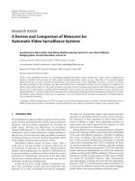
3. GENERAL VEHICLE DESIGN METHODOLOGY
Vehicle design methodology follows the V-cycle model where
from a requirements definition the process moves to func-
tional design, architecture design, system-integration design,
and component design before testing and verifying the same
steps in reverse chronological order (Figure 2).
In the automotive domain, system integrator (car man-
ufacturers) collaborate with system designer (tier 1 supplier,
e.g., Valeo) while themselves collaborate with component de-
signers (tier 2 supplier, e.g., Freescale); see (Figure 3).
This includes various domains such as electronics, soft-
ware, control, and mechanics. However, design and valida-
tion requires a modeling environment to integrate all these
disciplines. Unfortunately, running a complete multidomain
exploration through simulation is unfeasible. Although com-
ponent reuse helps somewhat reduce the challenge, it pre-
vents from all the possible customizations existing in cur-
rent system-on-chip design methodologies. Indeed, system
on chip makes intensive uses of various IPs and among them
parametrizable IPs w hich best fit the requirements of the
application. This allows new concurrent design methodolo-
gies between embedded software design, architecture, inter-
microcontroller communication and implementation. This
flattening of the design process can be best managed through
platform-based design at the TLM level.
4. PLATFORM-BASED TLM DESIGN PROCESS
Platforms have been proposed by semiconductor manufac-
turers in an effort to ease system-level design and allow
system designers to concentrate on essential issues such as
hardware-software partitioning, system parameters tuning,
and design of specific hardware accelerators. This makes
the reuse of platform-based designs easier than specific
designs.
4.1. Platforms and IBM platform driven
design methodology
The IBM CoreConnect platform [28] described in Figure 4
allows the easy connection of various components, system
core, and peripheral core to the CoreConnect bus architec-
ture.
It also includes IPs of PLB to OPB and OPB to PLB
bridges and direct memory access (DMA) controller, OPB-
attached external bus controller (EBCO), universal asyn-
chronous receiver/transmitter (UART), universal interrupt
controller (UIC), and double data rate (DDR) memory con-
troller. Several other peripherals are available among them
CAN controllers. The platform does not specify a specific
processor core although IBM family of embedded Pow-
erPC processors connection is straightforward. This plat-
form which mainly specifies a model-based platform have all
associated tools and libraries for quick ASIC or FPGA plat-
form design. System core and peripheral core can be any type
of user-designed components whether hardware accelerators
or specific peripherals and devices.
4 EURASIP Journal on Embedded Systems
Application
software
Platform
software
Embedded
software
Sensors/actuators Mechanical
Mixed-mode signal
Electronics Multiphysics
Digital Analog
Implementation
Architecture
Functional
Executable specifications
Figure 3: Decomposition.
System
core
System
core
System
core
Peripheral
core
Peripheral
core
bus
bridge
DCR bus
Arbiter
Arbiter
Processor local bus On-chip peripheral bus
CoreConnect bus architectur e
On-chip
memory
Processor
core
Auxiliary
processor
OCM
I/F
FPU
I/F
DCR bus
CoreConnect block diagram
Figure 4: IBM CoreConnect platform.
4.2. IBM SystemC TLM platform
The SystemC IEEE standard [29] is a system-level mod-
eling environment which allows the design of var ious ab-
straction levels of systems (Figure 5). It spawns from un-
timed functional to cycle accurate. In between, design space
exploration with hardware-software part itioning is con-
ducted with timed functional level of abstraction. Using the
model-driven architecture (MDA) terminology [30]wecan
model computation independent model (CIM), platform-
independent model (PIM), and platform-specific model
(PSM). Besides, SystemC c an model hardware units at RTL
level and be synthesizable for various target technologies us-
ingtoolssuchasSynopsys[11] and Celoxica [12], which in
turn allows multiobjective SystemC space exploration of be-
havioral synthesis options on area, performance, and power
consumption [31] since for any system, all three criteria can-
not be optimally met together.
This important point allows SystemC abstraction-level
platform-based evaluation taking into account area and en-
ergy aspects, and this for proper design space exploration
with implementation constraints. In addition to these lev-
els of abstraction, transaction-level modeling and abstrac-
tion level [8, 9] have been introduced to fasten simulation of
communications between components by considering com-
munications exchange at transaction level instead of bus cy-
cle accurate levels. Benefits of TLM abstraction-level design
have been clearly demonstrated [8, 9].
Using the IBM CoreConnect SystemC modeling envi-
ronment PEK [32], designers are able to put together Sys-
temC models for complete systems including PowerPC pro-
cessors, CoreConnect bus structures, and p eripherals. These
models may be simulated using the standard OSCI SystemC
[29] runtime libraries and/or vendor environments. The
IBM CoreConnect SystemC modeling environment TLM
platform models and environment provide designers with a
Muhammad Omer Cheema et al. 5
HW/SW partition
Refine communication
Matlab
SystemC
SDL Estenel Other
Functional decomposition
Untimed functional
UTF
Assign “execution time”
Timed functional
Bus cycle accurate
BCA
RTLRTOS
Software Hardware
Abstr.
RTOS
Design exploration
Refine behavior
Cycle accurate
Target RTOS/core
Task partitioning
SystemC
Performance analysis
HW/SW partitioning
TF
Figure 5: SystemC system design flow.
system simulation/verification capability with the following
characteristics.
(i) Simulate real application software interacting with
models for IP cores and the environment for full sys-
tem functional and timing verification possibly under
real-time constraints.
(ii) Verify that system supports enough bandwidth and
concurrency for target applications.
(iii) Verify core interconnections and communications
through buses and other channels.
(iv) Model the tr ansactions occurring over communica-
tion channels with no restriction on communication
type.
These objectives are achieved with additional practical as-
pectssuchassimulationperformancemustbeenoughtorun
a significant software application with an operating system
booted on the system. In addition, the level of abstraction
allows the following.
(i) Computation (inside a core) does not need to be mod-
eled on a cycle-by-cycle basis, a s long as the input-
output delays are cycle-approximate which implies
that for hardware accelerators both SystemC and C are
allowed.
(ii) Intercore communication must be cycle-approxi-
mate, which implies cycle-approximate protocol mod-
eling.
(iii) The processor model does not have to be a true archi-
tectural model; a software-based instruction set simu-
lator (ISS) can be used, provided that the performance
and timing accuracy are adequate.
In order to simulate real software, including the initializa-
tion and internal register programming, the models must be
“bit-true” and register accurate, from an API point of view.
6 EURASIP Journal on Embedded Systems
That is, the models must provide APIs to allow programming
of registers as if the user were programming the real hardware
device, including the proper number of bits and address off-
sets. Internal to the model, these “registers” may be coded in
any way (e.g., variables, classes, structs, etc.) as long as their
API programming makes them look like real registers to the
users. Models need not be a precise architectural representa-
tion of the hardware. They may be behavioral models as long
as they are cycle-approximate representations of the hard-
ware for the transactions of interest (i.e., the actual transac-
tions being modeled). There may be several clocks in the sys-
tem (e.g., CPU, PLB, OPB). All models must be “macro syn-
chronized” with one or more clocks. This means that for the
atomic transactions being modeled, the transaction bound-
aries (begin and end) are synchronized with the appropriate
clock. Inside an atomic transaction, there is no need to model
it on a cycle-by-cycle basis. An atomic transaction is a set of
actions implemented by a model, which once started, is fin-
ished, that is, it cannot be interrupted. Our system-design
approach using IBM’s PowerPC 405 evaluation kit (PEK)
[32] allows designers to evaluate, build, and verify SoC de-
signs using transaction-level modeling. However, PEK does
not provide synthesis ( area estimate) or energy consumption
tools.
4.2.1. SW development, compilation,
execution, debugging
In PEK, the PowerPC processors (PPC 405/PPC450) are
modeled using an instruction-set simulator (ISS). The ISS is
instantiated inside a SystemC wrapper module, which imple-
ments the interface between the ISS and the PLB bus model.
The ISS runs synchronized with the PLB SystemC model (al-
though the clock frequencies may be different). For running
a software over this PowerPC processor, code should be writ-
ten in ANSI C and it should be compiled using GNU cross
compiler for PowerPC architecture.
The ISS works in tandem with a dedicated debugger
called RiscWatch (RW) [33]. RW allows the user to debug
the code running on the ISS while accessing all architectural
registers and cache contents at any instance during the exe-
cution process.
4.2.2. HW development, compilation,
execution, monitoring
Hardware modules should be modeled in SystemC using
the IBM TLM APIs. Then these modules can be added
to the platform by connecting them to the appropriate
bus at certain addresses which were dedicated in software
for these hardware modules. Both, synthesizable and non-
synthesizable SystemC can be used for modeling of hardware
modules at this level but for getting area and energy esti-
mates, it is important that SystemC code be part of standard
SystemC synthesizable subset draft (currently under review
by the OSCI synthesis working group) [34]. If we want to
integrate already existing SystemC hardware modules, wrap-
pers should be written that wrap the existing code for mak-
ing it compatible with IBM TLM APIs. We have written
generic interfaces which provide a generalized HW/SW in-
terface hence reducing the modeling work required to gener-
ate different interfaces for every hardware module based on
its control flow.
For simulation of SystemC, standard systemc functional-
ity can be used for .vcd file generation, bus traffic monitor-
ing and other par ameters. We have also written the dedicated
hardware modules which are connected with the appropriate
components in the system and provide us with the exact tim-
ing and related information of various events taking place in
the hardware environment of the system.
4.2.3. Creating and managing transactions
In a real system, tasks may execute concurrently or sequen-
tially. A task that is executed sequentially, after another task,
must wait till the first task has completed before starting. In
this case, the first task is called a blocking task (transaction).
A task that is executed concurrently with another need not
wait for the first one to finish before starting. The first task,
in this case, is called a nonblocking task (transaction).
Transactions may be blocking or nonblocking. For ex-
ample, if a bus master issues a blocking transaction, then
the transaction function call will have to complete before the
master is allowed to initiate other transactions. Alternatively,
if the bus master issues a nonblocking transaction, then the
transaction function c all will return immediately, allowing
the master to do other work while the bus completes the re-
quested transaction. In this case, the master is responsible for
checking the status of the transaction before being able to use
any result from it. Blocking or nonblocking transactions are
not related to the amount of data being transferred or to the
types of transfer supported by the bus protocols. Both multi-
byte burst transfers as well as single-byte transfers may be
implemented as blocking or nonblocking transactions.
When building a platform, the designer has to specify the
address ranges of memory and peripherals attached to the
PLB/OPB busses. The ISS, upon encountering an instruction
which does a load/store to/from a memory location on the
bus, will call a function in the wrapper code which, in turn,
issues the necessary transactions on the PLB bus. The address
ranges of local memory, bus memory, cache sizes, cacheable
regions, and so forth, can all be configured in the ISS and the
SystemC models.
4.2.4. IP parameterization
Various parameters can be adjusted for the processor IPs and
other IPs implemented in the system. For a processor IP,
when the ISS is started, it loads a configuration file which
contains all the configurable parameters for running the ISS.
The configuration file name may be changed in the Tcl script
invoking the simulation. The parameters in the file allow the
setting of local memory regions, cache sizes, processor clock
period, among other characteristics. For example, we can ad-
just the value of data and Instruc tion Cache sizes to b e 0,
1024, 2048, 4096, 8192, 16384, 32768, and 65536 for the 405
Muhammad Omer Cheema et al. 7
processor. Besides setting the caches sizes, the cache regions
need to be configured, that is, the user needs to specify which
memory regions are cacheable or not. This is done by setting
appropriate values into special purpose registers DCCR and
ICCR. These are 32-bit registers, and each bit must be set to
1 if the corresponding memory region should be cacheable
The PowerPC uses two special-purpose registers (SPRs)
for enabling and configuring interrupts. The first register is
the machine state register (MSR) which controls processor
core functions such as the enabling and disabling of inter-
rupts and address translation. The second register is the ex-
ception vector prefix register (EVPR). The EVPR is a 32-bit
register whose high-order 16 bits contain the prefix for the
address of an interrupt handling routine. The 16-bit inter-
rupt vector offsets are concatenated to the right of the high-
order bits of the EVPR to form the 32-bit address of an in-
terrupt handling routine. Using RiscWatch commands and
manipulating startup files to be read from RiscWatch, we
can enable/disable cachebility, interrupts, and vary the cache
sizes. While on the other hand, CPU, bus, and hardware IP
configuration-based parameters can be adjusted in top level
file for hardware description where the hardware modules are
being initialized.
Provision of these IPs and ease of modeling makes IBM
TLM a suitable tool for platform generation and its perfor-
mance analysis early in the system design cycle.
5. PROPOSED METHODOLOGY
It should be clear from Section 4 that IBM PEK provides al-
most all important aspe cts of system design. That is why we
have based our methodology for HW/SW codesign on this
tool. However, our methodology will be equally valid for all
other tools having similar modeling and simulation func-
tionality. Our HW/SW codesign approach has the following
essential steps.
(a) Image processing chain development.
(b) Software profiling.
(c) Hardware modeling of image processing operators.
(d) Performance/cost comparison for HW/SW implemen-
tations.
(e) Platform generation, system design space exploration.
(a) Image processing chain development
Oursystemcodesignapproachstartsfromdevelopmentof
image processing chain (IPC). Roughly speaking, an image
processing chain consists of various image processing oper-
ators placed in the form of directed graph according to the
data flow patterns of the application. An image processing
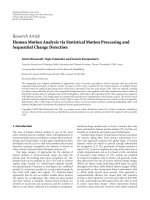
chain is shown in Figure 6.
This IPC describes the working of a Harris corner detec-
tor. IPC development process is very rapid as normally most
of the operators are already available in the operator’s library
and they need only to be initialized in a top-level function to
form an image processing chain and secondly it provides a
very clean and modular way to optimize various parts of the
application without the need of thorough testing and debug-
K = Sxx ∗ Syy − Sxy ∗ Sxy
Output image
Sxy
Sy y
Sxx
Gauss 3
× 3Gauss3× 3Gauss3× 3
Ixx Ixy I yy
Multiplications
Ix Iy
Sobel
Input image
Figure 6: Harris corner detector chain.
ging. In our case, we have used coding guidelines as recom-
mended by numerical recipes [35] which simplifies the IPC
development process even further.
(b) Software profiling
In this step, we execute the image processing chain over the
PowerPC 405 IP provided with PowerPC evaluation kit. Us-
ing RisCWatch commands, we get the performance results
of various software components in the system and detect the
performance bottlenecks in the system. S oftware profiling is
done for various data and instruction caches sizes a nd bus
widths. This information helps the system designer take the
partitioning decisions in later stages.
(c) Hardware modeling of image processing operators
In the next step of our system design approach, area and en-
ergy estimates are obtained for the operators implemented in
the image processing chain. At SystemC behavioral level, the
tools for estimating area and energy consumption have re-
cently been showing their progress in the EDA industry. We
use Celoxica’s agility compiler [12] for area estimation in our
case but our approach is valid for any behavior al-level syn-
thesis tool in the market. As we advocate the fast chain devel-
opment through libraries containing image processing oper-
ators, similar libraries can also be developed for equivalent
SystemC image processing operators which will be reusable
over a range of projects hence considerably shortening the
hardware development times as well. At the end of this step,
we have speed and area estimates for all the components of
the image processing chain to be synthesized. This informa-
tion is stored in a database and is used during HW/SW par-
titioning done in the next step.
Another important thing to be noted is that HW synthe-
sis is also a multiobjective optimization problem. Previously,
8 EURASIP Journal on Embedded Systems
[31]haveworkedoverefficient HW synthesis from SystemC
and shown that for a given SystemC description, various HW
configurations can be generated varying in area, energy, and
clock speeds. Then the most suitable configuration out of the
set of pareto optimal configurations can be used in the rest of
the synthesis methodology. Right now, we do not consider
this HW design space exploration for optimal area/energy
and s peed constraints but in our future work, we plan to in-
troduce this multiobjective optimization problem in our syn-
thesis flow as well.
(d) Performance comparison for HW/SW implementations
At this stage of system codesign, system designer has profiling
results of software as well as hardware implementation costs
and the performance of the same operator in the hardware.
So, in this stage performance of various individual operators
is compared and further possibilities of system design are ex-
plored.
(e) Platform generation, system-design space exploration
Like traditional hardware/software codesign approaches, our
target is to synthesize a system based on a general purpose
processor (in our case, IBM PowerPC 405) and extended
with the help of suitable hardware accelerators to signifi-
cantly improve the system performance without too much
increase in the hardware costs. We have chosen PowerPC 405
as a gener al purpose processor in our methodology because
of its extensive usage in embedded systems and availability
of its systemC models that provide ease of platform design
based on its architecture. Our target platform is shown in
Figure 7. Our target is to shift the functionality from image
processing chain to the hardware accelerators such that sys-
tem gets good performance improvements without too much
hardware costs.
In this stage, we perform the system-level simulation.
Based on the results of last step, we generate various con-
figurations of the system putting different operators in hard-
ware and then observing the system performance. Based on
these results and application requirements, a suitable con-
figuration is chosen and finalized as a solution to HW/SW
codesign issue.
(f) Parameter tuning
In the last step of image processing chain synthesis flow, we
perform the parameterization of the system. At this stage, our
problem becomes equivalent to (application specific stan-
dard products) ASSP parameterization. In ASSP, hardware
component of the system is fixed; hence only tuning of some
soft parameters is performed for these platforms to improve
the application perform ance and resource usage. Examples of
such soft parameters include interrupt and arbitration prior-
ities. Further parameters associated with more detailed as-
pects of the behavior of individual system IPs m ay also be
available. We deal with the problem manually instead of re-
lying on a design space exploration algorithm and our ap-
proach is to start tuning the system with the maximum re-
Memory
PLB
Bridge
OPB
Peripherals
Hardware accelerators
IBM PPC
405
Figure 7: Target platform built using IBM TLM.
sources available and keep on cutting down the resource
availability until the system performance remains well within
the limits and bringing down the value of a parameter does
not dr amatically affect system performance. However, in the
future we plan to tackle this parameterization problem using
automatic multiobjective optimization techniques.
6. EVALUATION RESULTS
We have tested our approach of HW/SW codesign for Harris
corner detector application described in Figure 6. Harris cor-
ner detector is frequently used for point-of-interest (PoI) de-
tection in real-time embedded applications during data pre-
processing phase.
The first step, according to our methodology, was to de-
velop image processing chain (IPC). As mentioned in the
previous section, we use numerical recipes guidelines for
component-based software development a nd it enables us to
develop/modify IPC in shor ter times because of utilization
of existing library elements and clarity of application flow. At
this stage, we put all the components in software. Software is
profiled for various image sizes and results are obtained. Next
step is to implement hardware and estimate times taken for
execution of an oper ator entirely implemented in hardware
and compare it to the performance estimates of software.
The results obtained from hardware synthesis and its per-
formance as compared with software-based operations are
shown in Ta ble 1 and Figure 6.
Results in Table 1 show the synthesis results of behavioral
SystemC modules for different operators computing differ-
ent sizes of data. We can see that with the change in data size,
memory requirements of the operator also change, while the
part of the logic which is related to computation remains the
same. Similarly, critical path of the system remains the same
as it mainly depends on computational logic structure. Based
on the synthesized frequencies and number of cycles required
to perform each operation, last column shows the computa-
tion time for each hardware operato r for a given size of data.
It is again worth mentioning that synthesis of these opera-
tors depends largely on the intended design. For example,
adding multiport memories can result in acceleration in read
Muhammad Omer Cheema et al. 9
Table 1: Synthesis results for Harris corner detector chain.
Module name
Area (computational logic and memory)
Critical path (ns) Synth. freq. (MHz) Total comp. time (μs)
Size Comp. logic slices memory (bits)
Sobel
8 × 8 218 18432 14.41 69.39 1.845
16 × 16 220 18432 14.41 69.39 7.376
32 × 32 222 36864 14.41 69.39 29.514
64 × 64 224 131072 14.41 69.39 118.06
P2P Mul
8 × 8 151 36864 11.04 90.33 1.417
16 × 16 151 36864 11.04 90.33 5.668
32 × 32 152 73728 11.04 90.33 22.67
64 × 64 152 262144 11.04 90.33 90.69
Gauss
8 × 8 184 18432 16.37 61.1 2.095
16 × 16 186 18432 16.37 61.1 8.38
32 × 32 188 36864 16.37 61.1 33.52
64 × 64 190 131072 16.32 61.1 134.1
K = coarsity
computation
8 × 8 351 36864 19.32 51.76 2.473
16 × 16 352 73728 19.32 51.76 9.892
32 × 32 353 147456 19.32 51.76 39.567
64 × 64 354 294912 19.32 51.76 158.269
Computation time (μs)
0
500
1000
1500
2000
2500
3000
3500
8 × 8
16
× 16
32
× 32
64
× 64
8
× 8
16
× 16
32
× 32
64
× 64
8
× 8
16
× 16
32
× 32
64
× 64
8
× 8
16
× 16
32
× 32
64
× 64
Size
Communication
Software
Computation
Sobel P2P Mul Gauss K
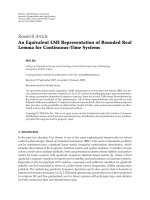
Figure 8: HW performance versus SW performance of operators.
operations from memory while u nrolling the loops in Sys-
temC code can result in performance improvement at a cost
of an increase in area.
Figure 8 shows the comparison of execution times of
an operator in its hardware and software implementations.
There are two things to be noticed here. Firstly, operator
computation time for hardware has been shown with two dif-
ferent parameters: computation and communication. Look-
ing at Ta ble 1, one might feel that all hardware implementa-
tions will be much faster than their software version but one
needs to realize here that implementing a function in hard-
ware requires the data to be communicated to the hardware
module which requires changes in software design where
computation functions are replaced by data transfer func-
tions. Although image processing applications seem to be
computation intensive, it should be noted that most of the
time is taken up by communication while computation is
only a fraction of total time taken by the hardware. An ideal
function to be implemented in hardware will be the one
which has lesser data to be transferred from/to the hardware
to/from the general purpose processor. Secondly, in the ex-
ample, we can see that Gaussian and Sobel oper ators seem
to be better candidates to be put in hardware while coarsity
computation in hardware lags in performance than its soft-
ware version because of lesser computation and more com-
munication requirements of the function.
After the performance comparison of operators in hard-
ware and software, next step was to generate the platform and
perform the system-level simulation for various configura-
tions. For our system-level simulation, our general purpose
processor (PowerPC 405) was running at 333 MHz while it
had 16 Kbytes of data and instruction caches.
At first simulation run, we realized that due to data ac-
cesses, original software was spending a lot of time in mem-
ory access operations. We optimized the software w hich re-
sulted in an optimized version of the software. After that, we
started exploring HW/SW codesign options by generating
various versions and getting the simulation results. Table 2
shows a few of the configurations generated and the CPU cy-
cles taken by the system during the simulation. A quick look
at the results shows that taking into consideration of hard-
ware implementation cost, configuration 7 provides a good
speedup where we have implemented Gaussian and Gradient
functions in the hardware. Table 1 shows that adding these
operators to hardware will result in a slight increase in com-
putation logic while a bit more increase in memory and at
that cost a speedup of more than 2.5 can be obtained.
10 EURASIP Journal on Embedded Systems
Memory
Sobel Gauss
CAN
IBM
embedded
PowerPC
(a)
Speedup
0
0.5
1
1.5
2
2.5
3
Sobel Gauss Sobel+K Gauss+K
Software
version
Optimized
software
Speedup for v arious configurations
Configuration
(b)
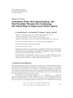
Figure 9: (a) Platform configuration 7. (b) Full HW/SW design space explor ation results.
Cycles/pixel
0
2000
1000
3000
4000
5000
No cache 4K 16K 64K
3876
816
742.5 742
Cache sizes (instruction and data)
Figure 10: Various cache sizes and system performance.
CAN bus
Figure 11: Platforms networked through CAN bus.
Figure 9 graphically represents Ta ble 2. We can see that
the configuration involving Sobel and Gaussian operators
gives significant speedups while configurations involving
point-to-point multiplication and coarsity computation (K)
result in worse performance. Based on these results, a system
designer might choose configuration 7 for an optimal solu-
tion. Or if he has strong area constraints, configurations 1
and 3 can be possible solutions for codesigned system.
When configuration 7 was chosen to be the suitable con-
figuration for our system, next step was the parameterization
of the system. Although parameterization involves bus width
adjustment, arbitration scheme management and interrupt
routine selection, for the sake of simplicity we show the re-
sults for optimal sizes of c aches. Figure 10 shows the results
for various cache sizes and corresponding performance im-
provement. We can see that cache results in significant per-
formance improvements until 16K of data and instruction
cache sizes. But after that, the performance improvements
with respect to cache size changes reach a saturation point
and there is almost no difference of performance for 16K and
64K caches in the system. Hence we choose 16K data and in-
struction caches sizes for our final system.
This approach allowed us to alleviate the problem of se-
lecting inadequate microcontrollers for intelligent vehicle de-
sign such as those described Section 2. This process can be
repeated with other applications in order to build a system
based on networked platforms; see Figure 11.
Lastly, we will mention the limitations of the methodol-
ogy. It should be noticed that we have chosen small image
sizes for our system design. Although TLM-level simulation
is much faster than RTL-level simulations, it still takes a lot of
time for simulation of complex systems. Increasing the image
sizes beyond 256
× 256 for the given example makes it in-
creasingly difficult for exploring the design space thoroughly
as it required multiple iterations of simulation for each con-
figuration and one iteration itself takes hours or even days to
complete. For larger image sizes where simulation time will
dominates the system design time, RTL-level system proto-
typing and real-time execution over hardware prototyping
boards seem to be a better idea where although system proto-
typing will take longer times but significant time savings can
be made by preferring real-time execution over simulations.
The approach of [36] can be used in this context.
7. FUTURE WORK: COMBINING UML-BASED
SYSTEM-DESIGN FLOW WITH SYSTEMC TLM
PLATFORM FOR INTELLIGENT VEHICLES DESIGN
The work presented so far described the potentials of Sys-
temC TLM platform-based design for the system design
of embedded applications through the customization of
Muhammad Omer Cheema et al. 11
Table 2: Various configurations and speedups for point-of-interest detection.
Config. no. Hardware implement Time (cycle) Cycle/pixel Speedup over software version
1 Sobel 3726350 909.75 2.07
2
P2P Mul 5419590 1323.14 1.42
3
Gauss 3490064 852.06 2.21
4
K = coarsity comp. 4725762 1153.75 1.63
5
Sobel + P2P Mul 4970836 1213.58 1.55
6
Sobel + K 4277108 1044.22 1.80
7
Sobel + Gauss 3041510 742.56 2.53
8
Gauss + P2P Mul 4734654 1155.92 1.63
9
Gauss + K 4040826 986.52 1.91
10
Optimized software 4175000 1019.29 1.85
11
Original software version 7717000 1884.03 1
UML
scheduling analysis
model
UML
performance analysis
model
Correcting
or change
Correcting updating
transformation
Transformation
view extraction
UML design model,
platform independent
UML framework,
platform independent
including variations
UML smart sensor
model
Derivation to
obtain a specific
system
Specify
sensors
Adapting code
generation
for specific
sensors
Transformation
with WCET
valuation
UML platform model
numerical information: WECT
of elementary actions,
number of CPU
···
UML design model,
platform specific
Symbolic execution
schedulability validation
with AGATHA
Performance analysis
(to identify bottlenecks, to explore
design and/or platform alternatives) with
LQN solver
TranslationTranslation
Feedback
Feedback
Figure 12: Accord/UML design methodology.
microcontrollers. Clearly important benefits come from this
approach with the possibility to get access to implementation
details (area, energy consumption) without lowering the de-
sign abstraction details down to implementation. This key
point clearly contributes to the reduction of the design cycle
and the ease of the design space exploration. On the other
hand, several research projects have advocated the use of
UML-based system design for real-time embedded systems
[16–19]. The Accord/UML is a model-based methodology
dedicated for the development of embedded real-time appli-
cations [16](Figure 12). The main objectives of the method-
ology is to specify and prototype embedded real-time sys-
tems through three consistent and complementary models
describing structure, interaction, and behavior. Examples of
applications include smart transducer integration in real-
time embedded systems [19].
12 EURASIP Journal on Embedded Systems
C level area/energy consumption
estimates
UML/SysML
requirements
Perf./area/energy
Intelligent vehicle
system requirements
Functional
specifications
TLM
SystemC
platform
UML/SysML to PIM
systemC TLM
Performance/area
Energy consumption
Pareto front analysis
SystemC TLM level
PIMSystemCTLMtoPSM
SystemC TLM transform
Platform configuration
selected
SystemC TLM
Platform to VHDL platform
PIMtoPSMtransformation
HW/SW platform
generation for FPGA
platforms
and download
SystemC level area/energy
consumption estimates
System to platform generation
SystemC TLM level with area and energy
Platform-to-platform generation
SystemC TLM level to VHDL/C/C++
Platform execution
Figure 13: UML/SysML/TLM SystemC platform-based desig n methodology for intelligent vehicles.
One key step of the Accord/UML methodology is the
model transformation from a UML design model platform
independent to a UML design model platform specific. This
is mainly accomplished through a transformation with a
worst-case execution time (WCET) valuation. This PSM
could be improved by iterating through a UML performance
analysis model which would again influence the transforma-
tion. This performance analysis model could be conducted
using SystemC TLM platform model and include additional
analysis with area and energy consumption as we did in the
previous section. The objectives of the ProMARTE working
group is to define a UML profile for modeling and analysis of
real-time and embedded systems (MARTE) that answers to
the RFP for MARTE [17]. These examples of UML-based de-
sign methodolog ies of embedded real-time systems suggest
that UML and platform SystemC TLM design methodolo-
gies may be combined for intelligent vehicles design. In this
regard, the autosar organization have released its UML pro-
file v1.0.1 as a metamodel to describe the system, software,
and hardware of an automobile [37]. This profile is expected
Muhammad Omer Cheema et al. 13
to be used as well for intelligent vehicles design. However,
translation from UML/SysML to SystemC have only recently
been tackled. Work has been conducted on the description
of executable platforms at the UML-level as well as the trans-
lation of UML-based application descriptions to SystemC
[27]. However, this work is far from getting down to a Sys-
temC level of the platform we used in this study. In [25] they
present a UML2.0 profile of SystemC language exploiting
MDA capabilities. No significant example of the methodolo-
gies is shown. In [23] a bi-directional UML-SystemC trans-
lation tool called UMLSC is described. According to the au-
thors more work remains to be done to extend UML to make
it better suited for hardware specification and improve the
translation tool. In [26] translation from UML to SystemC
for stream processing applications is presented. This work
allows the translation of a stream processor, however, not
a full-fledged processor. It is an implementation of the ab-
stract model in UML 2.0. A very recent significant exam-
ple of translation is provided in [38] using network on chip.
However, all the works mentioned so far did not use (1) Sys-
temC TLM platform-based design and (2) area and energy
consumption of platform configurations.
We propose a UML/SysML to SystemC design flow
methodology exclusively targeting platforms, that is, we are
not interested to directly translate UML to hardware level nor
we are interested to translate UML to SystemC. In a SystemC
TLM, platform modules have SystemC interface but can be
written with C. So UML structural parts are met with struc-
tural part of SystemC TLM platform while internal behav-
ior of modules provided in C. This requires for area/energy
consumption tradeoffs C-based synthesis and energy esti-
matetoolssuchas[39]. Our proposed flow t ransforms UML
to SystemC TLM platforms with design space exploration at
SystemC TLM level for timing, area, and energy (Figure 13).
In a combined UML-SystemC design methodology, UML
is used to capture the static system architecture and the hig h-
level dynamic behavior while SystemC is used for design im-
plementation.
The transformation of the SystemC TLM to VHDL plat-
form is straightforward and will be described in a future pub-
lication [40]. The use of FPGA platforms allows faster pro-
totyping especially if one considers actual intelligent vehicle
driving conditions [41, 42]. This overall design flow will be
thefocusoffuturework[43].
8. CONCLUSIONS
In this paper, we have proposed a platform-based SystemC
TLM system-level design methodology for embedded ap-
plications. This methodology emphasizes on components-
based software design and hig h-level (TLM) modeling and
simulation. Our proposed design flow facilitates the process
of system design by higher leveling hardware modeling and
behavioral synthesis of hardware modules. We have showed
that using the methodology, complex image processing ap-
plications can be synthesized within very short time hence
increasing the productivity and reducing overall time to mar-
ket for an electronic system. The introduction of Autosar
UML profile suggests the use of a combination of UML based
and SystemC TLM platform-based joint methodologies. Mi-
crocontrollers customized with our approach could bene-
fit from higher-level specification. Future work will extend
to raising the design methodology abstraction level to com-
bined UML/SysML/TLM SystemC platform design flow.
REFERENCES
[1] T. Bucher, C. Curio, J. Edelbrunner, et al., “Image processing
and behavior planning for intelligent vehicles,” IEEE Transac-
tions on Industrial Electronics, vol. 50, no. 1, pp. 62–75, 2003.
[2] L. Li, J. Song, F Y. Wang, W. Niehsen, and N N. Zheng, “IVS
05: new developments and research trends for intelligent vehi-
cles,” IEEE Intelligent Systems, vol. 20, no. 4, pp. 10–14, 2005.
[3] J. C. McCall and M. M. Trivedi, “Video-based lane estimation
and tracking for driver assistance: survey, system, and evalua-
tion,” IEEE Transactions on Intelligent Transportation Systems,
vol. 7, no. 1, pp. 20–37, 2006.
[4] A. P. Girard, S. Spry, and J. K. Hedrick, “Intelligent cruise-
control applications: real-time, embedded hybrid control soft-
ware,” IEEE Robotics & Automation Magazine,vol.12,no.1,
pp. 22–28, 2005.
[5] W. van der Mark and D. M. Gavrila, “Real-time dense stereo
for intelligent vehicles,” IEEE Transactions on Intelligent Trans-
portation Systems, vol. 7, no. 1, pp. 38–50, 2006.
[6]K.D.M
¨
uller-Glaser,G.Frick,E.Sax,andM.K
¨
uhl, “Multi-
paradigm modeling in embedded systems design,” IEEE Trans-
actions on Control Systems Technology, vol. 12, no. 2, pp. 279–
292, 2004.
[7] Freescale Semiconductors, />[8] F. Ghenassia, Ed., Transaction-Level Modeling with SystemC:
TLM Concepts and Applications for Embedded Systems, Spring-
er, New York, NY, USA, 1st edition, 2006.
[9] L. Cai and D. Gajski, “Transaction level modeling: an over-
view,” in Proceedings of the 1st IEEE/ACM/IFIP International
Conference on Hardware/Software Codesign and System Synthe-
sis (CODES+ISSS ’03), pp. 19–24, Newport Beach, Calif, USA,
October 2003.
[10] N. Calazans, E. Moreno, F. Hessel, V. Rosa, F. Moraes, and E.
Carara, “From VHDL register transfer level to SystemC trans-
action level modeling: a comparative case study,” in Proceed-
ings of the 16th Symposium on Integrated Circuits and Systems
Design (SBCCI ’03), pp. 355–360, Sao Paulo, Brazil, September
2003.
[11] Synopsys, “Behavioral Compiler User Guide,” Version
2003.10, 2003.
[12] Agilit y, />[13] O. Capdevielle and P. Dalle, “Image processing chain construc-
tion by interactive goal specification,” in Proceedings of the
1st IEEE International Conference Image Processing (ICIP ’94) ,
vol. 3, pp. 816–820, Austin, Tex, USA, November 1994.
[14] Y. Abchiche, P. Dalle, and Y. Magnien, “Adaptative Concept
Building by Image Processing Entity Structuration,” Institut de
Recherche en Informatique de Toulouse IRIT, Universit
´
ePaul
Sabatier.
[15] R. B. France, S. Ghosh, T. Dinh-Trong, and A. Solberg,
“Model-driven development using UML 2.0: promises and
pitfalls,” Computer, vol. 39, no. 2, pp. 59–66, 2006.
[16] Accord/UML, />uml/AccordUML presentation.htm.
[17] ProMARTE, />[18] Protes project, />14 EURASIP Journal on Embedded Systems
[19] C. Jouvray, S. G
´
erard, F. Terrier, S. Bouaziz, and R. Reynaud,
“UML methodology for smart transducer integration in real-
time embedded systems,” in Proceedings of IEEE Intelligent
Vehicles Symposium, pp. 688–693, Las Vegas, Nev, USA, June
2005.
[20] S. G
´
erard, C. Mraidha, F. Terrier, and B. Baudry, “A UML-
based concept for high concurrency: the real-time object,” in
Proceedings of the 7th IEEE International Symposium on Object-
Oriented Real-Time Distributed Computing (ISORC ’04),pp.
64–67, Vienna, Austria, May 2004.
[21] H. Sa
´
ıedian and S. Raguraman, “Using UML-based rate
monotonic analysis to predict schedulability,” Computer,
vol. 37, no. 10, pp. 56–63, 2004.
[22]J L.Dekeyser,P.Boulet,P.Marquet,andS.Meftali,“Model
driven engineering for SoC co-design,” in Proceedings of the
3rd International IEEE Northeast Workshop on Circuits and
Systems Conference (NEWCAS ’05), pp. 21–25, Quebec City,
Canada, June 2005.
[23] C. Xi, L. J. Hua, Z. ZuCheng, and S. YaoHui, “Modeling Sys-
temC design in UML and automatic code generation,” in Pro-
ceedings of the 11th Asia and South Pacific Design Automation
Conference (ASP-DAC ’05), vol. 2, pp. 932–935, Yokohama,
Japan, January 2005.
[24] J Kreku, M. Etel
¨
aper
¨
a, and J P. Soininen, “Exploitation oF
UML 2.0—based platform service model and systemC work-
load simulation in MPEG-4 partitioning,” in Proceedings of the
International Symposium on System-on-Chip (SOC ’05),pp.
167–170, Tampere, Finland, November 2005.
[25] E. Riccobene, P. Scandurra, A. Rosti, and S. Bocchio, “A SoC
design methodology involving a UML 2.0 profile for Sys-
temC,” in Proceedings of the Design, Automation & Test in Eu-
rope Conference (DATE ’05), vol. 2, pp. 704–709, Munich, Ger-
many, March 2005.
[26] Y. Zhu, Z. Sun, W F. Wong, and A. Maxiaguine, “Using UML
2.0 for system level design of real time SoC platforms for
stream processing,” in Proceedings of the 11th IEEE Interna-
tional Conference on Embedded and Real-Time Computing Sys-
tems and Applications, pp. 154–159, Hong Kong, August 2005.
[27] K. D. Nguyen, Z. Sun, P. S. Thiagarajan, and W F. Wong,
“Model-driven SoC design via executable UML to SystemC,”
in Proceedings of the 25th IEEE International Real-Time Sys-
tems Symposium (RTSS ’04), pp. 459–468, Lisbon, Portugal,
December 2004.
[28] IBM CoreConnect, />[29] IEEE 1666 Standard SystemC Language Reference Manual,
/>.pdf.
[30] MDA Guide Version 1.0.1 June 2003, OMG.
[31] S. Chtourou and O. Hammami, “SystemC space exploration of
behavioral synthesis options on area, performance and power
consumption,” in Proceedings of the 17th International Confer-
ence on Microelectronics (ICM ’05), pp. 67–71, Islamabad, Pak-
istan, December 2005.
[32] IBM PEK v1.0, />power/library/pa-pek/.
[33] “RiscWatch Debuggers User Guide,” 15th edition, IBM Num-
ber: 13H6964 000011, May 2003.
[34] OSCI SystemC Transaction-Level Modeling Working Group
(TLMWG), />working groups.html.
[35] W. H. Press, B. P. Flannery, S. A. Teukolsky, and W. T. Vetter-
ling, Numerical Recipes: The Art of Scientific Computing,Cam-
bridge University Press, Cambridge, UK, 1989.
[36] R. Ben Mouhoub and O. Hammami, “MOCDEX: multipro-
cessor on chip multiobjective design space exploration with
direct execution,” EURASIP Journal of Embedded Systems,
vol. 2006, Article ID 54074, 14 pages, 2006.
[37] UML Profile for Autosar v1.0.1, />[38] E. Riccobene, P. Scandurra, A. Rosti, and S. Bocchio, “A
model-driven design environment for embedded systems,” in
Proceedings of the 43rd ACM/IEEE Design Automation Confer-
ence (DAC ’06), pp. 915–918, San Francisco, Calif, USA, July
2006.
[39] Orinoco Dale, />php.
[40] O. Hammami and Z. Wang, “Automatic PIM to PSM Transla-
tion,” submitted for publication.
[41]S.Saponara,E.Petri,M.Tonarelli,I.delCorona,andL.
Fanucci, “FPGA-based networking systems for high data-rate
and reliable in-vehicle communications,” in Proceedings of the
Design, Automation & Test in Europe Conference (DATE ’07),
pp. 1–6, Nice, France, April 2007.
[42] C. Claus, J. Zeppenfeld, F. M
¨
uller, and W. Stechele, “Using
partial-r un-time reconfigurable hardware to accelerate video
processing in driver assistance system,” in Proceedings of the
Design, Automation & Test in Europe Conference (DATE ’07),
pp. 1–6, Nice, France, April 2007.
[43] O. Hammami, “Automatic Design Space Exploration of Au-
tomotive Electronics: The Case of AUTOSAR,” submitted for
publication.