Báo cáo hóa học: " Research Article Embedded Localization and Communication System Designed for Intelligent Guided Transports" ppt
Bạn đang xem bản rút gọn của tài liệu. Xem và tải ngay bản đầy đủ của tài liệu tại đây (2.43 MB, 8 trang )
Hindawi Publishing Corporation
EURASIP Journal on Embedded Systems
Volume 2007, Article ID 79095, 8 pages
doi:10.1155/2007/79095
Research Article
Embedded Localization and Communication System
Designed for Intelligent Guided Transports
Yassin ElHillali,
1
Atika Rivenq,
1
Charles Tatkeu,
2
J. M. Rouvaen,
1
andJ.P.Ghys
2
1
Departement Opto-Acousto-Electronique (DOAE), Institute des Etalons de Mesure Nationaux IEMN,
Universit
´
e de Valenciennes et du Hainaut Cambresis (UVHC), Le Mont Houy, 59313 Valencie nnes Cedex 9, France
2
Institut National de Recherche sur les Transports et leur S
´
ecurit
´
e(INRETS),20rueElis
´
ee Reclus,
59650 Villeneuve d
´
eAscq Cedex, France
Received 14 October 2006; Accepted 16 February 2007
Recommended by Samir Bouaziz
Nowadays, many embedded sensors allowing localization and communication are being developed to improve reliability, security
and define new exploitation modes in intelligent guided transports. This paper presents the architecture of a new system allow-
ing multiuser access and combining the two main functionalities: localization and high data flow communication. This system
is based on cooperative coded radar using a transponder inside targets (trains, metro, etc). The sensor uses an adapted digital
correlation receiver in order to detect the position, compute the distance towards the preceding vehicle, and get its status and
identification. To allow multiuser access and to combine the two main functionalities, an original multiplexing method inspired
from direct sequence-code division multiple access (DS-CDMA) technique and called sequential spreading spectrum technique
(SSS2) is introduced. This study is focused on presenting the implementation of the computing unit according to limited resources
in embedded applications. Finally, the measurement results for railway environment will be presented.
Copyright © 2007 Yassin ElHillali et al. This is an open access article distributed under the Creative Commons Attribution License,
which permits unrestricted use, distribution, and reproduction in any medium, provided the original work is properly cited.
1. INTRODUCTION
Localization and communication systems become increas-
ingly more important to ensure the common transport safety
that is maritime [1, 2], airway, or terrestrial. Actually all boats
and the planes are already equipped with systems based on a
transponder which allows the localization and data exchange.
For example, in the maritime transport domain, a system
called automatic identification system (AIS) is deployed. This
system equips all chips with a device using a GPS receiver to
estimate the boat position and a VHF transponder to broad-
cast this position and other information to all chips around.
However, in guided transport domain, no system is actually
able to ensure these functionalities.
In the present paper, a new system, called Communica-
tion, Detection and Identification of Broken-Down Trains
(CODIBDT), is proposed to optimize the exploitation mode
inside automatic guided transports. Indeed, a trafficpertur-
bation occurs when a train is broken down along the line.
It is then necessary to accost [3], in safety conditions, this
broken train by another train. The line is divided in parts
called districts of about 1 km. When a train is in a district, it
is declared to be engaged. No coach can go in until the train
leaves it. This is the security system in the current networks.
If the real time distance between the trains was known, the
accosting phase duration between the two vehicles could be
reduced significantly. This distance could be transmitted to
the exploitation center, which is in charge of procedure man-
agement. This measurement should be provided in different
environments where the train moves like free area, viaduct,
and subway tunnel.
However, in a subway tunnel, due to the multipath reflec-
tions, a conventional radar system analyzing signal echoes
on an obstacle is inefficient. In fact, as shown in Figure 1,
the radar receives multiple echoes especially if an obstacle is
closer than the train targeted. In such case, it is difficult to
detect the right obstacle among all these echoes.
The designed cooperative radar CODIBDT overcomes
these problems and its principle relies on a transponder sys-
tem: transmitters and receivers equip, respectively, the front
and the rear of each train. Another advantage is that it not
only provides a real time distance measurement, but also al-
lows communication with high data flow between the sen-
sors. Then it could be helpful to develop many applications
among which exchange information such as audio-video
records in order, for example, to increase security feeling and
2 EURASIP Journal on Embedded Systems
T1
T2
T3
Figure 1: The problems occurred in a subway tunnel.
quality of service inside trains (wireless Internet). For this
purpose, an appropriate multiplexing method for this sen-
sor has been proposed to favor high data flow and robustness
according to signal-to-noise ratio (SNR) criterion.
This paper is focused on developing hardware and soft-
ware implementation of this system developed using flexible
components such as FPGA. Finally, the results obtained with
the implemented mock-up are presented in free space area
and in tunnel.
2. THE PRINCIPLE OF THE PROPOSED
CODIBDT SYSTEM
The implemented system has a broadband of about 100 MHz
that can be used. We propose to develop a new coding algo-
rithm to exploit this band in order to establish high data rate
communications between t rains and operator centers. The
CODIBDT sensor is able
(i) to detect the position, get the identification and the
status of the train,
(ii) to compute, in real time, the distance towards the pre-
ceding vehicle,
(iii) to allow high data rate communications for exchang-
ing data information between trains.
Its principle relies on a transponder system using an in-
terrogator/responder pair (see Figure 2(a)) which equips, re-
spectively, the front and the rear of vehicle. As shown on
Figure 2(b), the first vehicle (interrogator) sends a signal at a
frequency of 2.2 GHz, towards the preceding vehicle (respon-
der). This signal, which has its own radar code, is a binary
pseudo random sequence (BPRS). It is received by the sec-
ond vehicle ahead. The sensor of this vehicle ahead process
and sends a replica of the received signal that is amplified,
filtered and filled out with data at the same time. These data
contain information about its identification (or identity), its
working mode or state (broken-down or not, failure status),
and so forth. The new signal sent at 2.4 GHz frequency is re-
ceived by the interrogator that is able to deduce the intertrain
distance and to recover the data sent by the responder (iden-
tification, status (broken-down or not)).
The frequency choice is an important item, because it de-
pends on the line configuration and the possibility of resolv-
ing both effects of masking and multipath, which strongly
affect the resulting signal. The present choice is settled in the
(a) The CODIBDT radar mock-up
Localization Code
Modulator
MUX
2.4GHz
Interrogator
Correlation
processing
extraction
2.2GHz
Demodulator
Upward link
CODIBDT
Antenna
Data I
Distance
Data T
Down ward link
2.4GHz
Demodulator
Localization
Code
Data I
Processing
Data T
MUX
Modulator
2.2GHz
Trans p onder
(b) The CODIBDT transmitter/receiver desig n architecture
Figure 2
range of 1–10 GHz band. For low power transmitter consum-
ption, we choose industrial, scientific and medical (ISM)
band for our sensor on (2.2 GHz and 2.4 GHz).
Such a cooperative radar system for which the target be-
comes active like in a transponder, the proposed system has
great advantages among others.
(i) It works in each kind of environment: free space, sub-
way tunnel or viaducts areas. In the later case, conven-
tional radar systems based on distance measurement
using signal echoes on obstacles proves inefficient.
(ii) Moreover, the pseudorandom sequence (BPRS) used,
combined with a correlation receiver, are very adapted
to the detection of signals over noisy communication
channels and can be generated easily.
On the following paragraphs, this paper will present charac-
teristics and p erformances in terms of BER and data rate of
the system.
3. PRESENTATION OF THE MULTIPLEXING
TECHNIQUE
This paragraph is focused on technical solutions to develop
the new communication feature and optimize the combina-
tion of the two main functionalities: localization and high
data rate communication. In order to provide this combina-
tion with high speed data flow, different coding methods [4]
were tested and one of them is presented hereafter. Indeed,
Yassin ElHillali et al. 3
Frame
C1023 C1023
Data burst
Figure 3: General structure of a frame sent with the coding tech-
nique.
C1023
+31
−31 −31
···
+31
C1023
Figure 4: Detailed structure of the frame sent by the SSS2 tech-
nique.
Table 1: Number of code according to register length.
Register length 3456 7 8 9 10
Number of different orthogonal code
226618164860
this method allows a continuous refreshing of the measure-
ment of distance and also ensures a sufficient flow rate for
communication with a suitable BER.
The technique is inspired from the DS-CDMA [5]and
uses families of orthogonal codes (Binary Pseudo-Random
Sequence—BPRS) with two different lengths. The first one
has code length of 1023 bits (C1023) intended for the local-
ization and the second is constituted by short codes of 31 bits
long (C31) dedicated to the communication.
Different codes families (BPRS codes, Gold codes,
Kasami codes) were studied for use in this system and were
compared according to the number, the length, and the max-
imum of their crosscorrelation. These sequences look like a
noise and so have a spread spectrum. The selected codes have
the same length: 2
n−1
[6, 7], an autocorrelation peak and a
low l evel only for the crosscorrelation. The BPRS, also called
m-sequences, presents an autocorrelation with a peak at 2
n−1
and a− 1 level elsewhere. They have good performances even
when the signal to noise ratio is ver y low. Their implemen-
tation is simple. They could be easily generated using shift
registers with XOR feedback. The number of these codes per
family is a function of their length is presented in Ta ble 1.
These families are considered as the reference in this
study.
As we can see on Figure 3, the method consists of send-
ing periodically the code of localization to ensure a regu-
lar renewal of the distance measurement. We propose to in-
sert between two codes of localization a variable structure of
coded data burst. Between two localization codes we insert
1023 bits, which can be divided into several short codes.
The proposed coding technique is entitled SSS2 for Se-
quential Spectrum Spreading using 2 codes.
The spreading with the C1023 is used to assume local-
ization function. The second one is used to code data com-
munications with the C31 in the classical DS-CDMA (Di-
rect Sequence CDMA) [5, 7–9]. This technique allows us to
send 33 bits of data between two codes of localization. The
length of the first code is chosen to reach the required dis-
10
−8
10
−7
10
−6
10
−5
10
−4
10
−3
10
−2
10
−1
10
−0
BER
−20 −15 −10 −50
SNR (dB)
Figure 5: The BER obtained with SSS2 technique.
tance (about one kilometer) and due to important number
of reply codes (60). The length of the second code affects the
rate of communication, if we choose a shorter one, we will
have a higher rate but the robustness will decrease signifi-
cantly. Multiple simulations have been done and the length of
31 bits seems to be a good trade-off between the data rate and
the robustness to noise. Figure 4 shows the standard struc-
ture of the frame transmitted by this method.
To calculate the distance, the correlation between the re-
ceived signal and the reference codes (C1023) is computed.
The correlation peak allows the synchronization process.
Then, to recover data, a second correlation between the re-
ceived signal and the C31 code is used.
4. PERFORMANCES
The SSS2 technique has been simulated in additive white
Gaussian noise (AWGN) channel in order to evaluate its per-
formances in terms of data flow rate and bit-error rate (BER).
On Figure 5, the bit-error rate corresponding to several
signal-to-noise ratio values, obtained by simulations (with
sufficient number of iterations) is given for this technique.
The SNR is defined as
SNR
= 10 log
E
σ
2
,(1)
where E is the maximum power transmitted by the radar and
σ is the standard deviation of noise.
Simulation results show that, in AWGN channel, SSS2
technique is robust to noisy environments (i.e., SNR less than
−2 dB). Moreover, a BER of 10
−5
can be reached with SNR
equals to
−2 dB with this method.
Concerning the data flow rate, it could be estimated as
the following:
data flow
=
number of bits sent
time
=
N
2 ∗ L
c
/f
,(2)
4 EURASIP Journal on Embedded Systems
(a) The patch antenna used in our system
0
−5
−10
−15
−20
−25
−30
−35
−40
−45
(b) The antenna radiation pattern
Figure 6
where N is the number of data bits sent periodically, L
c
is the
length of the localization code and f is the signal frequency.
Furthermore to ensure periodical renewal of the distance
measurement, we choose to limit the data frame length to
1023 (as the localization code). And because we spread the
data with a code length 31, the maximum numbers of bits
which could be sent is limited to 33 bits/frame,
data flow
≈ 1.6Mbps. (3)
In this case, the data flow which could be reached is about
1.6 Mbps for a clock of 100 MHz. This data flow rate asso-
ciated to the robustness of this technique in noisy environ-
ments (BER of 10
−5
with SNR greater than −2 dB) makes this
multiplexing method very interesting for our application.
Concerning the localization characteristics, it gives a
resolution in distance, which is between 1.5 meter and
3 meters depending of the clock frequency used (50 MHz or
100 MHz). The maximal range obtained is about 800 meters
in tunnels and 700 meters in free space.
Moreover, the radar detection is physically limited in low
range, under 10 or 15 m, due to the recovery time of the sen-
sor.
The actual laboratory mock-up integrates a multiplexing
SSS2 technique using flexible components like FPGA [6]as
described in Figure 6(a). We use 2
× 2 patches antennas for
each link with a beam aperture of 20
◦
to operate in curves.
Figure 6(b) show the r adiation pattern of each antenna.
Table 2 gives a summary of performances of the whole
radar sensor.
The resolution and range in free space and tunnel are the
same of about 1.5 meters for a clock frequency of 100 MHz,
and we can reach 700 meters maximum range in free space
and 800 meters in tunnels. The range of ours system in tunnel
is greater that in free space because the behavior of the tunnel
is like a “wave guide” for the frequencies used by ours system.
The preliminary results of simulations confirm the per-
formance of the SSS2 technique (weak BER and sufficient
high-speed information exchange).
Table 2: Performances of CODIBDT.
Coding SSS2
Maximum flow 1.6 Mbps
SNR for BER
= 10
−5
−2dB
Range in free space 700 m
Range in subway 800 m
Resolution at 100 MHz 1.5 m
Sensor characteristics
Antenna aperture 15
◦
Antenna type 2 × 2 patches
Antenna size (cm) 12
× 12
5. CODIBDT IMPLEMENTATION
5.1. Architecture choices
In order to estimate the C1023 flight time between the in-
terrogator and the responder, a local peak is detected in the
calculated cross-correlation between the received signal and
the reference (C1023). To compute this correlation, the first
solution is to use a conventional DSP processor. So, we have
to estimate the number of operations needed per second. In-
deed, the maximum frequency of the transmitted signal is
about 50 MHz (or 100 MHz) and the received signal has to
be sampled at least twice per chip. So, the signal to be pro-
cessed has a given rythm of about 100 MHz (or 200 MHz)
and for each chip, at least 1023 MAC (Multiplication and ac-
cumulation) are needed to calculate the intercorrelation. Due
to the fact that DSP processors carry out a MAC operation
by clock edge, a processor which runs up to 102.3 GHz or
(204.6 GHz) is required. However, such a processor does not
exist on the market yet. For these reasons, we mother choose
new generation components such as FPGA which propose a
more flexible and easily reconfigurable structure and where
treatments may be massively parallelized.
Yassin ElHillali et al. 5
Data to be sent
Coder
FIFO data
EPROM C31
10 bits counter
EPROM
C1023
Synchronization
unit
FIFO Loc
Code 31
selection
Code 1023
selection
Receiv er
input
Correlator 1023
Correlator 31 Delay line
Data detection
Maximum
detection
11 bits counter
Computed
distance
Receiv ed
data
Output toward
emitter
Figure 7: Different modules implemented in the FPGA component of the interrogator.
So the computing unit needed for calculating the cor-
relation as well as the detection unit will be implemented
on FPGA components. The correlation unit is composed by
a barrel of parallel multipliers and accumulators. Thus, the
system can run as fast as the frequency of the received sig-
nal (i.e., in real time). Moreover the detection unit is pro-
grammed such a “state machine.” In our design the biggest
element, which consumes the largest resources of the FPGA,
is the correlator module. Multiple architectures to imple-
ment this module is developed to optimize the resources con-
sumption according to limitation imposed by the specifica-
tion or the embedded applications.
5.2. Global implementation of the CODIBDT process
As shown on the previous paragraphs, the proposed system
is made of a couple of microwave transmitting and receiv-
ing equipments fixed on each train (resp., interrogator and
responder). The transmitting equipment includes a modula-
tor and a demodulator, respectively, at 2.2 GHz and 2.4 GHz
frequencies and includes also a computing unit composed
by an ADC—analogue-to-digital converter—and FPGA de-
vice. The receiving equipment is similar but the modulator
will run at 2.4 GHz and the demodulator at 2.2 GHz. The
localization-communication procedure will be made in sev-
eral successive steps, which can be summarized as follows.
The interrogator will build the global frame and send it
towards the responder at 2.2 GHz.
The responder demodulates the signal at 2.2 GHz and
identifies the localization frame, then it replaces the inter-
rogator data frame by his data frame.
The new global frame will be sent to the interrogator at
2.4 GHz.
Besides the interrogator, the computing unit will calcu-
late the correlation between the received signal and the dif-
ferent code (C1023 and C31) in order to estimate the fly time
and decode the data frame.
The working of the computing unit will now be de-
scribed.
5.3. The interrogator computing unit
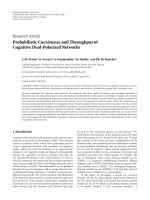
As shown in Figure 7, the interrogator computing unit can be
divided into two principal blocks: the transmitting block (at
the top of the figure), and the receiving block (at the bottom).
It has different inputs and outputs such as
(i) data input,
(ii) C31 and C1023 code selection,
(iii) received signal which is plugged into the ADC output,
(iv) signal output,
(v) estimated distance and received data output.
It contains different modules as the following.
(i) EPROM’s where the two different BPRS codes used are
stored.
(ii) Coder module: to spread the data with data code.
(iii) Data FIFO where spreaded data will be stored.
(iv) FIFO Loc where localization code will be copied.
(v) Synchronization unit which builds the global frame by
synchronizing the read operation for the two FIFOs.
(vi) Some counters: 10 bits counter to transfer the local-
ization code from EPROM to FIFO loc, and 11 bits
counter used as a time references (reference counter).
(vii) Two correlators.
6 EURASIP Journal on Embedded Systems
(viii) Peak detection to detect the peak present in the corre-
lation result between the received signal and the local-
ization code.
(ix) Data detection.
The communication localization process will start in the
interrogator FPGA by constructing the burst to be sent. The
coder component will modulates the C31 code stored in the
EPROM and put it in “FIFO Data” and the 10 bits counter
transfer the C1023 stored in the EPROM into the “FIFO Loc.”
When the reference counter is reset to zero, the synchro-
nization unit deals with orchestrating the sending of the lo-
calization code present in “FIFO LOC;” followed by 33
×C31
codes modulated by the data present in the “FIFO data.”
This signal will be received by the responder and will be
amplified, modified and sent back towards the interrogator.
Besides the interrogator the module “correlator 1023”
calculates the intercorrelation between the received signal
and reference code C1023 and in the same time the “corre-
lator 31” module calculates an intercorrelation between this
signal and reference code C31.
When “maximum detection” module detects a peak in
the correlation results with C1023, the value present in the
“11 bits counter” is raised up. This value represents the flight
time of the radar signal. Then the reception of the data is per-
formed also, by estimating the sign of the correlation result
with code C31. The “delay line” module is used to synchro-
nize the results of both correlators; because there are different
response times of about 10 chips and 5 chips.
5.4. The responder computing unit
Besides the responder, to ensure the function of localization,
a copy of the received signal is sent back to the interrogator.
And in order to exchange data, we exploit the C1023 code
sent by the interrogator to synchronize the two components.
To ensure that, we compute an intercorrelation between the
received signal and code C1023. The detection unit algorithm
will take care to detect a local maximum in a guard interval.
The presence of one peak indicates that a data frame is being
sent. Once the synchronization peak is detected, the sign cor-
responding to the second correlator peak will be estimated.
If the tr ansponder has some data to transmit, we wait until
a C1023 peak is detected; then, instead of sending a copy of
the received signal, the transponder will send the package of
modulated C31 present in the “FIFO data.”
At the first interrogator stage, the correlation function is
calculated using the C1023 code (Figure 8). The peak posi-
tion determines the distance and the synchronization for the
data frame. At the second stage, a second correlation is calcu-
lated with the C31 code to detect data information as by the
DS-CDMA decoding technique.
6. EXPERIMENTAL RESULTS
Some trials have been carried out with the preliminary
mock-up in real life conditions to evaluate the localization
and the communication functions. The measurements have
been made in the different environments the radar maybe
Receiv er
input
Correlator 1023
Correlator 31 Delay line Data detection
Receiv ed
data
Maximum
detection
Output
toward emitter
FIFO data
Coder
EPROM C31
Data to be sent
Code 31
selection
Figure 8: Different modules implemented in the FPGA component
of the interrogator.
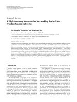
Figure 9: Measurement made in the tunnel using the realized
mock-up.
used. Figure 9 shows the mock up placed in the front of the
vehicles.
An example of the received signal from the transpon-
der located 100 meters far from the interrogator is shown on
Figure 10.
We can note on this graph that there are many inter-
ferences with other systems working in the same frequency
band, that is, 2.2 GHz to 2.4 GHz.
The architecture of this radar is efficient in these condi-
tions and avoids the interference effects. In fact, Figure 11
shows the performances of the correlation tools associated
to BPRS codes. The corresponding peaks could be easily de-
tected.
Figure 12 presents a zoom on the first 4000 samples of
the signal shown on Figure 10. It corresponds to a signal pro-
cessed with a signal analyzer using an oversampling ratio of
about 40. The signal has a rythm of about 50 MHz. The in-
trinsic central processing unit includes two ADC that can
work at 100 megasamples per second. An oversampling ra-
tio of about 2 or 4 could there be reached.
On Figure 13, the normalized intercorrelation result of
the received signal with the code C1023 is presented together
to the time reference. The delay time between the two signals
corresponds to the flight time relative to the distance.
On Figures 14 and 15, the result obtained after the corre-
lation between the received signal and the localization code
Yassin ElHillali et al. 7
−0.2
−0.1
0
0.1
0.2
0.3
0.4
0.5
Received signal (V)
0246810
×10
5
Samples
Figure 10: Received signal target at 100 meters.
−0.2
0
0.2
0.4
0.6
0.8
1
1.2
Corelation va lues
0 1000 2000 3000 4000 5000 6000
Samples
Figure 11: Correlation result with C1023.
C1023 (black color) and data code C31 (gray color) are rep-
resented.
We can see on Figure 14 that, between two localization
codes,aseriesofdatasentcouldbeextractedeasily.More-
over , on Figure 15, the data peaks are periodically distributed
spaced of 31 chips. Between the localization peak and the first
data peak, only a 26 chips delay exists (instead of 31) due to
the difference in response times between localization corre-
lation and data correlation. This difference, as we mentioned
previously, is about 5 chips.
7. CONCLUSION
In this paper, new cooperative radar dedicated to automatic
guided trains is presented. This sensor allows two function-
alities: localization and high data flow communication. To
−0.25
−0.2
−0.15
−0.1
−0.05
0
0.05
0.1
0.15
0.2
Received signal
0 500 1000 1500 2000 2500 3000 3500 4000
Samples
Figure 12: Received signal zoom first 4000 samples.
0
0.2
0.4
0.6
0.8
1
Correlation values
0 200 400 600 800 1000 1200
Samples
Reference
Calculated correlation
Figure 13: Correlation result with C1023.
combine these functionalities, original multiplexing meth-
ods called SSS2 have been proposed. This technique is in-
spired from CDMA base and uses successively two cod-
ing frames to ensure the multiplexing between the localiza-
tion and the communication part and at the same time to
give automatically multiuser access. With this method, the
CODIBDT sensor achieves interesting performances in terms
of localization range that is about of 800 m in subway tunnel
and 700 m in open space w i th resolution of 1.5 m. However,
the communication between vehicles is established with flow
data rate up to 1.6 Mbits/s.
Many simulations have been computed to look further
the system’s performance in terms of computing time and
complexity. And in order to validate simulations results, a
mock-up have been build outfitted with flexible component
like FPGA devices. This FPGA device contains the computing
8 EURASIP Journal on Embedded Systems
−0.6
−0.4
−0.2
0
0.2
0.4
0.6
0.8
Normalized correlation values
1.21.41.61.822.22.42.6
×10
5
Samples
C31
C1023
Figure 14: Correlation result with C1023 (black) and C31 (gray).
−0.6
−0.4
−0.2
0
0.2
0.4
0.6
0.8
Normalized correlation values
1.16 1.18 1.21.22 1.24
×10
5
Samples
C31
C1023
Figure 15: Correlation result with C1023 (black) and C31 (gray)
zoom of Figure 14.
unit of the whole system (interrogator and responder) in-
cluding also the coding technique and the detection algo-
rithm. Future works will be oriented to multiplexing tech-
nique enhancement. Higher data flow rates could be reached
by the same system using other coding method. Simulations
of these methods will be performed with real channel model
corresponding to free area and tunnel.
REFERENCES
[1] J. King, “The security of merchant shipping,” Marine Policy,
vol. 29, no. 3, pp. 235–245, 2005.
[2] T. Wahl, G. K. Høye, A. Lyngvi, and B. T. Narheim, “New pos-
sible roles of small satellites in maritime surveillance,” Acta As-
tronautica, vol. 56, no. 1-2, pp. 273–277, 2005.
[3] B. Fremont, A. Menhaj, P. Deloof, and M. Heddebaut, “A co-
operative collision avoidance and communication system for
railway transports,” in Proceedings of IEEE Conference on Intelli-
gent Transportation Systems (ITSC ’00), pp. 216–221, Dearborn,
Mich, USA, October 2000.
[4] Y. Elhillali, C. Tatkeu, A. Rivenq, and J. M. Rouvaen, “Enhance-
ment and implementation of a localization and communication
system dedicated to guided transports,” in Proceedings of the 6th
International Conference on ITS Telecommunications (ITST ’06),
pp. 596–599, Chengdu, China, June 2006.
[5] T. Ottosson, “Coding, modulation and multiuser decoding
for DSCDMA systems,” Doktorsavhandlingar vid Chalmers
Tekniska Hogskola, 1343, p. 192, 1997.
[6] C. Tatkeu, P. Deloof, Y. Elhillali, A. Rivenq, and J. M. Rouvaen,
“A cooperative radar system for collision avoidance and com-
munications between vehicles,” in Proceedings of IEEE Intelligent
Transportation Systems Conference ( ITSC ’06), pp. 1012–1016,
September, Toronto, Canada 2006.
[7] C.Tatkeu,Y.Elhillali,A.Rivenq,andJ.M.Rouvaen,“Evalua-
tion of coding’s methods for the development of a radar sen-
sor for localization and communication dedicated to guided
transport,” in Proceedings of the 60th IEEE Vehicular Technol-
og y Conference (VTC ’04), vol. 3, pp. 2244–2247, Los Angeles,
Calif, USA, September 2004.
[8] R. Dixon, Ed., Spread Spectrum Techniques, IEEE Press, New
York, NY, USA, 1976.
[9] J. Glas, “Spread Spectrum Techniques,” Delft University of
Technology, 1996, />∼glas/ssc/techn/
techniques.html.