Báo cáo hóa học: " Research Article DART: A Functional-Level Reconfigurable Architecture for High Energy Efficiency" potx
Bạn đang xem bản rút gọn của tài liệu. Xem và tải ngay bản đầy đủ của tài liệu tại đây (1.27 MB, 13 trang )
Hindawi Publishing Corporation
EURASIP Journal on Embedded Systems
Volume 2008, Article ID 562326, 13 pages
doi:10.1155/2008/562326
Research Article
DART: A Functional-Level Reconfigurable Architecture for High
Energy Efficiency
S
´
ebastien Pillement,
1
Olivier Sentieys,
1
and Rapha
¨
el David
2
1
IRISA/R2D2, 6 Rue de Kerampont, 22300 Lannion, France
2
CEA, LIST, Embedded Computing Laboratory, Mailbox 94, F-91191 Gif-sur-Yvette, France
Correspondence should be addressed to S
´
ebastien Pillement,
Received 4 June 2007; Accepted 15 October 2007
Recommended by Toomas P. Plaks
Flexibility becomes a major concern for the development of multimedia and mobile communication systems, as well as classical
high-performance and low-energy consumption constraints. The use of general-purpose processors solves flexibility problems but
fails to cope with the increasing demand for energy efficiency. This paper presents the DART architecture based on the functional-
level reconfiguration paradigm which allows a significant improvement in energy efficiency. DART is built around a hierarchical
interconnection network allowing high flexibility while keeping the power overhead low. To enable specific optimizations, DART
supports two modes of reconfiguration. The compilation framework is built using compilation and high-level synthesis techniques.
A 3G mobile communication application has been implemented as a proof of concept. The energy distribution within the archi-
tecture and the physical implementation are also discussed. Finally, the VLSI design of a 0.13 x2009μm CMOS SoC implementing
a specialized DART cluster is presented.
Copyright © 2008 S
´
ebastien Pillement et al. This is an open access article distributed under the Creative Commons Attribution
License, which permits unrestricted use, distribution, and reproduction in any medium, provided the original work is properly
cited.
1. INTRODUCTION
Rapid advances in mobile computing require high-perform-
ance and energy-efficient devices. Also, flexibility has be-
come a major concern to support a large range of mul-
timedia and communication applications. Nowadays, dig-
ital signal processing requirements impose extreme com-
putational demands which cannot be met by off-the-shelf,
general-purpose processors (GPPs) or digital signal proces-
sors (DSPs). Moreover, these solutions fail to cope with the
ever increasing demand for low power, low silicon area, and
real-time processing. Besides, with the exponential increase
of design complexity and nonrecurring engineering costs,
custom approaches become less attractive since they cannot
handle the flexibility required by emerging applications and
standards. Within this context, reconfigurable chips such as
fieldprogrammablegatearrays(FPGAs)areanalternative
to deal with flexibility, adaptability, high performance, and
short time-to-market requirements.
FPGAs have been the reconfigurable computing main-
stream for a couple of years and achieved flexibility by sup-
porting gate-level reconfigurability; that is, they can be fully
optimized for any application at the bit level. However, the
flexibility of FPGAs is achieved at a very high silicon cost in-
terconnecting huge amount of processing primitives. More-
over, to be configured, a large number of data must be dis-
tributed via a slow programming process. Configurations
must be stored in an external memory. These interconnec-
tion and configuration overheads result in energy waste, so
FPGAs are inefficient from a power consumption point of
view. Furthermore, bit-level flexibility requires more com-
plex design tools, and designs are mostly specified at the
register-transfer level.
To increase optimization potential of programmable
processors without the fine-grained architectures penalties,
functional-level reconfiguration was introduced. Reconfig-
urable processors are a more advanced class of reconfigurable
architectures. The main concern of this class of architectures
is to support high-level flexibility while reducing reconfigu-
ration overhead.
In this paper, we present a new architectural paradigm
which aims at associating flexibility with performance and
low-energy constraints. High-complexity application do-
mains, such as mobile telecommunications, are particularly
2 EURASIP Journal on Embedded Systems
targeted. The paper is organized as follows. Section 2 dis-
cusses mechanisms to reduce energy waste during com-
putations. Similar approaches in the context of reconfig-
urable architectures are presented and discussed in Section 3.
Section 4 describes the features of the DART architecture.
The dynamic reconfiguration management in DART is pre-
sented in Section 5. The development flow associated with
the architecture is then introduced. Section 7 presents some
relevant results coming from the implementation of a mobile
telecommunication receiver using DART and compares it to
other architectures such as DSP, FPGA, and a reconfigurable
processor. Finally, Section 8 details the VLSI (very large-scale
integration) implementation results of the architecture in a
collaborative project.
2. ENERGY EFFICIENCY OPTIMIZATION
The energy efficiency (EE) of an architecture can be defined
by the number of operations it performs when consuming
1 mW of power. EE is therefore proportional to the compu-
tational power of the architecture given in MOPS (millions
of operations per second) divided by the power consumed
during the execution of these operations. The power is given
by the product of the elementary dissipated power per area
unit P
e
l, the switching frequency F
clk
, the square of the power
supply voltage V
DD
, and the chip area. The latter is the sum
of the operator area, the memory area, and the area of the
control and configuration management resources. P
e
l is the
sum of two major components: dynamic power which is the
product of the transistor average activity and the normalized
capacitance per area unit, and static power which depends on
the mean leakage of each transistor.
These relations are crucial to determine which parame-
ters have to be optimized to design an energy-efficient archi-
tecture. The computational power cannot be reduced since it
is constrained by the application needs. Parameters like the
normalized capacitance or the transistor leakage mainly de-
pend on technology process, and their optimization is be-
yond the scope of this study.
Thespecificationofanenergy-efficient architecture dic-
tates the optimization of the remaining parameters: the op-
erator area, the storage and control resources area, as well
as the activity throughout the circuit and the supply voltage.
The following paragraphs describe some useful mechanisms
to achieve these goals.
2.1. Exploiting parallelism
Since EE depends on the square of the supply voltage, V
DD
has to be reduced. To compensate for the associated perfor-
mance loss, full use must be made of parallel processing.
Many application domains handle several data sizes dur-
ing different time intervals. To support all of these data sizes,
flexible functional units must be designed, at the cost of la-
tency and energy penalties. Alternatively, functional units
can be optimized for only a subset of these data sizes. Op-
timizing functional units for 8- and 16-bit data sizes allows
to design subword processing (SWP) operators [1]. Thanks
to these operators, the computational power of the architec-
ture can be increased during processing with data-level paral-
lelism, without reducing overall performances at other times.
Operation- or instruction-level parallelism (ILP) is in-
herent in computational algorithms. Although ILP is con-
strained by data dependencies, its exploitation is generally
quite easy. It requires the introduction of several functional
units working independently. To exploit this parallelism, the
controller of the architecture must specify simultaneously to
several operators the operations to be executed as in very long
instruction word (VLIW) processors.
Thread-level parallelism (TLP) represents the number of
threads which may be executed concurrently in an algorithm.
TLP is more complicated to be exploited since it strongly
varies from one application to another. The tradeoff between
ILP and TLP must thus be adapted for each application run-
ning on the architecture. Consequently, to support TLP while
guaranteeing a good computational density, the architecture
must be able to alter the organization of its processing re-
sources [2].
Finally, application parallelism can be considered as an
extension of thread parallelism. The goal is to identify the
applications that may run concurrently on the architecture.
Contrary to threads, applications executed in parallel run on
distinct datasets. To exploit this level of parallelism, the archi-
tecture can be divided into clusters which can work indepen-
dently. These clusters must have their own control, storage,
and processing resources.
Exploiting available parallelism efficiently (depending on
application) can allow for some system-level optimization of
the energy consumption. The allocation of tasks can permit
the putting of some part of architecture into idle or sleep
modes [3] or the use of other mechanisms like clock gating
to save energy [4].
2.2. Reducing the configuration distribution cost
Control and configuration distribution has a significant im-
pact on the energy consumption. Therefore, the configura-
tion data volume as well as the configuration frequency must
both be minimized. The configuration data volume reflects
on the energy cost of one reconfiguration. It may be min-
imized by reducing the number of reconfiguration targets.
Especially, the interconnection network must support a good
tradeoff between flexibility and configuration data volume.
Hierarchical networks are perfect for this purpose [5].
If there are some redundancies in the datapath structure,
it is possible to reduce the configuration data volume, by dis-
tributing simultaneously the same configuration data to sev-
eral targets. This has been defined as the single configuration
multiple data (SCMD) concept. The basic idea was first in-
troduced in the Xilinx 6200 FPGA. In this circuit, configur-
ing “cells” in parallel with the same configuration bits were
implemented using wildcarding bits to augment the cell ad-
dress/position to select several cells at the same time for re-
configuration.
The 80/20 rule [6] asserts that 80% of the execution
time are consumed by 20% of the program code, and only
20% are consumed by the remaining source code. The time-
consuming portions of the code are described as being
S
´
ebastien Pillement et al. 3
regular and typically nested loops. In such a portion of code,
the same computation pattern is repeated many times. Be-
tween loop nests, the remaining irregular code cannot be op-
timized due to lack of parallelism. Adequate configuration
mechanisms must thus be defined for these opposite kinds of
processing.
2.3. Reducing the data access cost
Minimizing the data access cost implies reducing the num-
ber of memory accesses and the cost of one memory access.
Thanks to functional-level reconfiguration, operators may
be interconnected to exploit temporal and spatial localities
of data. Spatial locality is exploited by connecting operators
in a data-flow model. Producers and consumers of data are
directly connected without requiring intermediate memory
transactions. In the same way, it is important to increase the
locality of reference, and so to have memory close to the pro-
cessing part.
Temporal locality may be exploited—thanks to broadcast
connections. This kind of connection transfers one item of
data towards several targets in a single transaction. This re-
moves multiple accesses to data memories. The temporal lo-
cality may further be exploited—thanks to registers used to
build delay chains. These delay chains reduce the number of
data memory accesses when several samples of the same vec-
tor are concurrently handled in an application.
To reduce data memory access costs while providing a
high bandwidth, a memory hierarchy must be defined. The
high-bandwidth and low-energy constraints dictate the in-
tegration of a large number of small memories. To provide
large storage space, a second level of hierarchy must be added
to supply data to the local memories. Finally, to reduce the
memory management cost, address generation tasks have to
be distributed along with the local memories.
3. RELATED WORKS
Functional-level reconfigurable architectures were intro-
duced to trade off flexibility against performance, while re-
ducing the reconfiguration overhead. This latter is mainly
obtained using reconfigurable operators instead of LUT-
based configurable logic blocks. Precursors of this class of
architectureswereKressArray[7], RaPid [8], and RaW ma-
chines [9] which were specifically designed for streaming al-
gorithms.
These works have led to numerous academic and com-
mercial architectures. The first industrial product was the
Chameleon Systems CS2000 family [10], designed for ap-
plication in telecommunication facilities. This architecture
comprises a GPP and a reconfigurable processing fabric. The
fabric is built around identical processing tiles including
reconfigurable datapaths. The tiles communicate through
point-to-point communication channels that are static for
the duration of a kernel. To achieve a high throughput,
the reconfigurable fabric has a highly pipelined architecture.
Based on a fixed 2D topology of interconnection network,
this architecture is mainly designed to provide high speeds
in the telecommunication domain regardless of other con-
straints.
The extreme processor platform (XPP) [11]fromPACT
is based on a mesh array of coarse-grained processing array
elements (PAEs). PAEs are specialized for algorithms of a par-
ticular domain on a specific XPP processor core. The XPP
processor is hierarchical, and a cluster contains a 2D array of
PAEs, which can support point-to-point or multicast com-
munications. PAEs have input and output registers, and the
data streams need to be highly pipelined to use the XPP re-
sources efficiently.
The NEC dynamically reconfigurable processor (DRP-1)
[12] is an array of tiles constituted by an 8
×8matrixofpro-
cessing elements (PEs). Each PE has an 8-bit ALU, an 8-bit
data management unit, and some registers. These units are
connected by programmable wires specialized by instruction
data in a point-to-point manner. Local data memories are
included on the periphery of each tile. Data flow needs to be
carefully designed to take advantage of this architecture. NEC
DRP-1 provides sixteen contexts, by implementing a 16-deep
instruction memory in each PE. This approach permits the
reconfiguration of the processor in one cycle, but at the price
of a very high cost in configuration memory.
The XiRisc architecture [13] is a reconfigurable processor
based on a VLIW RISC core with a five-stage pipeline, en-
hanced with an additional run-time configurable datapath,
called pipelined configurable gate array (PiCoGA). PiCoGA
is a full-custom designed unit composed of a regular 2D
array of multicontext fine-grained reconfigurable logic cells
(RLCs). Thus, each row can implement a stage of a customiz-
able pipeline. In the array, each row is connected to other
rows with configurable interconnection channels and to the
processor register file with six global busses. Vertical chan-
nels have 12 pairs of wires, while horizontal ones have only
8 pairs of wires. PiCoGA supports dynamic reconfiguration
in one cycle by including a specific cache, storing four con-
figurations for each RLC. The reconfiguration overhead can
be optimized by exploiting partial run-time reconfiguration,
which gives the opportunity for reprogramming only a por-
tion of the PiCoGA.
Pleiades [14] was the first reconfigurable platform tak-
ing into account the energy efficiency as a design constraint.
It is a heterogeneous coarse-grained platform built around
satellite processors which communicate through a hierar-
chical reconfigurable mesh structure. All these blocks com-
municate through point-to-point communication channels
that are static for the duration of a kernel. The satellite pro-
cessors can be embedded FPGAs, configurable operators, or
hardwired IPs to support specific operations. Pleiades is de-
signedforlowpowerbutitneedstoberestrictedtoan
application domain to be very efficient. The algorithms in
the domain are carefully profiled in order to find the ker-
nels that will eventually be implemented as a satellite proces-
sor.
Finally, the work in [15] proposes some architectural im-
provements to define a low-energy FPGA. However, for com-
plex applications, this architecture is limited in terms of at-
tainable performance and development time.
4 EURASIP Journal on Embedded Systems
Memory
controller
Data memory
Configuration
controller
Configuration
memory
RDP1
RDP2
RDP3
RDP4
RDP5
RDP6
SB
SB
SB
SB
SB
SB
Segmented network
Optional
application
specific
operator
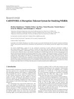
Figure 1: Architecture of a DART cluster.
4. DART ARCHITECTURE
The association of the principles presented in Section 3 leads
to the first definition of the DART architecture [16]. Two vi-
sions of the system level of this architecture can be explored.
The first one consists in a set of autonomous clusters which
have access to a shared memory space, managed by a task
controller. This controller assigns tasks to clusters according
to priority and resources availability constraints. This vision
leads to an autonomous reconfigurable system. The second
one, which is the solution discussed here, consists in using
one cluster of the reconfigurable architecture as a hardware
accelerator in a reconfigurable system-on-chip (RSoC). The
RSoC includes a general-purpose processor which should
support a real-time operating system and control the whole
system through a configurable network. At this level, the ar-
chitecture deals with the application-level parallelism and
can support operating system optimization such as dynamic
voltage and frequency scaling.
4.1. Cluster architecture
A DART cluster (see Figure 1) is composed of functional-
level reconfigurable blocks called reconfigurable datapaths
(RDPs); see Section 4.2.
DART was designed as a platform-based architecture so
at the cluster level, we have a defined interface to imple-
ment user dedicated logic which allows for the integration of
application-specific operators or an FPGA core to efficiently
support bit-level parallelism, for example.
The RDPs may be interconnected through a segmented
network, which is the top level of the interconnection hierar-
chy. According to the degree of parallelism of the application
to be implemented, the RDPs can be interconnected to carry
out high-complexity tasks or disconnected to work indepen-
dently on different threads. The segmented network allows
for dynamic adaptation of the instruction-level and thread-
level parallelisms of the architecture, depending on the pro-
cessing needs. It also enables communication between the
application-specific core and the data memory or the chain-
ing of operations between the RDPs and the user dedicated
logic.
The hierarchical organization of DART allows the con-
trol to be distributed. Distributing control and processing re-
sources through predefined hierarchical interconnection net-
worksismoreenergy-efficient for large designs than that
through global interconnection networks [5]. Hence, it is
possible to efficiently connect a very large number of re-
sources without being penalized too much by the intercon-
nection cost.
All the processing primitives access the same data mem-
ory space. The main task of the configuration controller
is to manage and reconfigure the RDP sequentially. This
controller supports the above-mentioned SCMD concept.
Since it sequences configurations rather than instructions, it
does not have to access an instruction memory at each cy-
cle. Memory reading and decoding do happen occasionally
when a reconfiguration occurs. This drastic reduction of the
amount of instruction memory reading and decoding leads
to significant energy savings.
4.2. Reconfigurable datapath architecture
The arithmetic processing primitives in DART are the RDPs
(see Figure 2). They are organized around functional units
(FUs) followed by a pipeline register and small SRAM mem-
ories, interconnected via a powerful communication net-
work. Each RDP has four functional units in the current
configuration (two multipliers/adders and two arithmetic
and logic units) supporting subword processing (SWP); see
Section 4.3. FUs are dynamically reconfigurable and can ex-
ecute various arithmetic and logic operations depending on
the stored configuration.
FUs process data stored in four small local memories, on
top of which four local controllers are in charge of providing
the addresses of the data handled inside the RDPs. These ad-
dress generators (AGs) share a zero-overhead loop support
and they are detailed in Section 4.4. In addition to the mem-
ories, two registers are also available in every RDP. These reg-
isters are used to build delay chains, and hence realizing time
data sharing.
All these resources communicate through a fully con-
nected network. This offers high flexibility and it is the sec-
ond level of the interconnection hierarchy. The organization
of DART keeps these connections relatively small, hence lim-
iting their energy consumption. Thanks to this network, re-
sources can communicate with each other in the RDP. Fur-
thermore, the datapath can be optimized for several kinds of
calculation patterns and can make data sharing easier. Since
a memory can simultaneously be accessed by several func-
tional units, some energy savings can be realized. Finally,
connections with global busses allow for the use of several
RDPs to implement massively parallel processing.
4.3. Architecture of the functional units
The design of efficient functional units is of prime impor-
tance for the efficiency of the global architecture. DART is
based on two different FUs which use the SWP [1]concept
S
´
ebastien Pillement et al. 5
Nested loop support
AG1 AG2 AG3 AG4
Data
mem1
Data
mem2
Data
mem3
Data
mem4
Multi-bus network
reg1 reg2
FU1 FU2 FU3 FU4
To se g m en t e d
network
Figure 2: Architecture of a reconfigurable datapath (RDP).
justified by the numerous data sizes that can be found in cur-
rent applications (e.g., 8 and 16 bits for video and audio ap-
plications). Consequently, we have designed arithmetic op-
erators that are optimized for the most common data format
(16 bits) but which support SWP processing for 8-bit data.
The first type of FU implements a multiplier/adder. De-
signing a low-power multiplier is difficult but well known
[17]. One of the most efficient architectures is the Booth-
Wallace multiplier for word lengths of at least 16 bits. The
designed FU includes the saturation of signed results in the
same cycle as the operation evaluation. Finally, as the multi-
plication has a 32-bit result, a shifter implements basic scal-
ing of the result. This unit is shown in Figure 3.
As stated before, FUs must support SWP. Synthesis and
analysis of various architectures have shown that implement-
ing three multipliers (one for 16-bit data and two for the
SWP processing on 8-bit data) leads to a better tradeoff be-
tween area, time, and energy than the traditional 4-multiplier
decomposition [18].
To decrease switching activity in the FU, inputs are
latched depending on whether SWP is used or not, leading to
a5%areaoverhead,butthepowerconsumptionisoptimized
(
−23% for 16-bit operations and −72% for 8-bit multiplica-
tions). Implementing addition on the various multipliers is
obvious and requires only a multiplexer to have access to the
adder tree.
The second type of functional unit implements an arith-
metic and logic unit (ALU) as depicted in Figure 4.Itcanper-
form operations like ADD, SUB, ABS, AND, XOR, and OR
and it is mainly based on an optimized adder. For this latter,
a Sklansky structure has been chosen due to its high perfor-
mance and power efficiency 11. Implementation of subtrac-
tion is made by using two’s complement arithmetic. Finally,
SWP is implemented by splitting the tree structure of the Δ
elements of the Sklansky adder. The FU has a 40-bit wide
operator to limit overflow in the case of long accumulation.
As for the multiplier, the unit can perform saturation in the
same processing cycle.
Two shifters at the input and at the output of the arith-
metic unit can perform left or right shifts of 0, 1, 2, or 4 bits
in the same cycle to scale the data. As for the multiplier, in-
puts are latched to decrease switching activity. Ta bl e 1 sum-
marizes performance results of the proposed functional units
on 0.18 μm technology from STMicroelectronics (Geneva,
Switzerland). The critical path of the global RDP comes from
the ALU implementation, and so pipelining the multiplier
unit is not an issue.
4.4. Address generation units
Since the controller task is limited to the reconfiguration
management, DART must integrate some dedicated re-
sources for address generation. These units must provide
the addresses of the data handled in the RDPs for each data
memory (see Figure 2) during the task processing. To be effi-
cient in a large spectrum of applications, the address genera-
tors (AGs) must support numerous addressing patterns (bit
reverse, modulo, pre-/postincrement, etc.). These units are
built around an RISC-like core in charge of sequencing the
accesses to a small instruction memory (64
×32 bits). In or-
der to minimize the energy consumption, these accesses will
take place only when an address has to be generated. For that,
the sequencer may be put in an idle state. Another module is
then in charge of waking up the sequencer at the right time.
Even if this method needs some additional resources, in-
terest in it is widely justified by the energy savings. Once
the instruction has been read, it is decoded in order to con-
trol a small datapath that will supply the address. On top
of the four address generation units of each RDP (one per
memory), a module provides a zero-overhead loop support.
Thanks to this module, up to four levels of nested loop can
be supported, with each loop kernel being able to contain
up to eight instructions without any additional cycles for its
management. Two address generation units are represented
in Figure 5 with the shared zero-overhead loop support.
5. DYNAMIC RECONFIGURATION
DART proposes a flexible and dynamic control of reconfig-
uration. The distinction between regular and irregular codes
6 EURASIP Journal on Embedded Systems
16
Input A
16
Input B
SWP
Demux
LL L L
L:latch
OP
Mux
Shift Shifter
32
Output
16 bits
Booth-Wallace
∗/+
8bits
carry-save
∗/+
8bits
carry-save
∗/+
Figure 3: Multiplication functional unit.
leads to the definition of two reconfiguration modes. Regular
processing is the time-consuming part of algorithms and it
is implemented—thanks to “hardware reconfigurations” (see
Section 5.1). On the other hand, irregular processing has less
influence on performance and it is implemented—thanks to
“software reconfigurations” (see Section 5.2).
5.1. Hardware reconfiguration
During regular processing, complete flexibility of the RDPs
is provided by the full use of the functional-level reconfigu-
ration paradigm at the cost of a higher reconfiguration over-
head. In such a computation model, the dataflow execution
paradigm is optimal. By allowing the modification of in-
terconnections between functional units and memories, the
architecture can be optimized for the computation pattern
to be implemented. The SCMD concept exploits the redun-
dancy of the RDPs by simultaneously distributing the same
configuration to several RDPs, and thus reducing the con-
figuration data volume. According to the regularity of the
computation pattern and the redundancy of configurations,
4 to 19 52-bit instructions are required to reconfigure all the
RDPs and their interconnections. Once these configuration
instructions have been specified, no other instruction read-
ing and decoding have to occur until the end of the loop ex-
ecution. The execution is controlled by the AGs which se-
quence input data and save the output in terminal memories.
For example, in Figure 6, the datapath is configured to
implement a digital filter based on MAC operations. Once
this configuration has been specified, the dataflow compu-
tation model is maintained as long as the filter needs this
pattern. At the end of the execution, a new computing pat-
tern can be specified to the datapath, for example, the square
of the difference between x(n)andx(n
− 1) in Figure 6.In
that case, 4 cycles are required to reconfigure a single RDP.
This hardware reconfiguration fully optimizes the datapath
structure at the cost of reconfiguration time (19 cycles for
the overall configuration without SCMD), and no additional
control data are necessary.
5.2. Software reconfiguration
Irregular processing represents the control-dominated parts
of the application and requires to change RDP configurations
at each cycle; a so-called software reconfiguration is used. To
reconfigure the RDPs in one cycle, their flexibility is limited
to a subset of the possibilities. As in VLIW processors, a cal-
culation pattern of read-modify-write type has been adopted.
In that case, for each operator needed for the execution, the
data are read and computed, then the result is stored back in
memory.
The software reconfiguration is only concerned with the
functionality of the operators, the size of the data, and their
origin. Thanks to these limitations on flexibility, the RDP
may be reconfigured at each cycle with only one 52-bit in-
struction. This is illustrated in Figure 7 which represents the
reconfiguration needed to replace an addition of data stored
in the memories Mem1 and Mem2 by a subtraction of data
stored in the memories Mem1 and Mem4.
Due to the reconfiguration modes and the SCMD con-
cept, DART can be fully optimized to efficiently support both
dataflow intensive computation processing and irregular
S
´
ebastien Pillement et al. 7
16 Input A
16 Input B
SWP
Demux
Shifter
Shift input
LL L L
Command
Mux
Shift output
Shifter
32
Output
Arithmetic unit
ADD, SUB, ABS
Logic unit
AND, OR, NOT
Figure 4: Arithmetic and logic functional unit.
Table 1: Implementation results and performances of the func-
tional units.
Area Delay Energy
(μm
2
)(ns)(10
−12
J)
Multiplier functional unit 37 000 3.97 88.90
ALU functional unit 28 850 5.33 39.62
processing for control parts. Moreover, the two reconfigura-
tion modes can be mixed without any constraints, and they
have a great influence on the development methodology. Be-
sides the design of the architecture, a compilation framework
has been developed to exploit these architecture and recon-
figuration paradigms. The joint use of retargetable compila-
tion and high-level synthesis techniques leads to an efficient
methodology.
6. DEVELOPMENT FLOW
To exploit the computational power of DART, the design of
development flow is the key to enhance the status of the ar-
chitecture. In that way, we developed a compilation frame-
work based on the joint use of a front end allowing for
the transformation and the optimization of C code, a retar-
getable compiler to handle compilation of the software con-
figurations, and high-level synthesis techniques to generate
the hardware reconfiguration of the RDP [19].
As in most of development methodologies for reconfig-
urable hardware, the key issue is to identify the different
kinds of processing. Based on the two reconfiguration modes
of the DART architecture, our compilation framework uses
two separate flows for the regular and irregular portions of
code. This approach has already been successfully used in the
PICO (program in, chip out) project developed at HP labs
to implement regular codes into a systolic structure, and to
compile irregular ones for an VLIW processor [20]. Other
projects such as Pleiades [21]orGARP[22] are also using
this approach.
The proposed development flow is depicted in Figure 8.
It allows the user to describe its applications in C. These
high-level descriptions are first translated into control and
dataflow graph (CDFG) by the front end, from which some
automatic transformations (loop unrolling, loop kernel ex-
tractions, etc.) are done to reduce the execution time. After
these transformations, the distinction between regular codes,
irregular ones, and data manipulations permits the transla-
tion of the high-level description of the application into con-
figuration instructions—thanks to compilation and architec-
tural synthesis.
6.1. Front end
The front end of this development flow is based on the SUIF
framework [23] developed at Stanford. It aims to generate
an internal representation of the program from which other
modules can operate. Moreover, this module has to extract
the loop kernels inside the C code and transmit them to
the module (gDART) in charge of transforming the regu-
lar portions of code into HW configurations. To increase
the parallelism of each loop kernel, some specific algorithms
have been developed inside the SUIF front end to unroll the
loops according to the number of functional units available
in the cluster. Finally, in order to increase the temporal lo-
cality of the data, other loop transformations have also been
8 EURASIP Journal on Embedded Systems
Zero-overheadloopsupport
@
Seq1
@
Seq4
···
Mem @1
64
×16 bits
Datapath
@1
Mem @4
64 ×16bits
Datapath
@4
Decod
Instr
◦
Decod
Instr
◦
Data
mem4
Data
mem1
Figure 5: Address generation units with zero-overhead loop support.
Configuration 1
Mem1 Mem2 Mem3
× +
y(n)+
= x(n)
∗
c(n)
Configuration 2
Rec
4cycles
Mem1 Mem3
−×
y(n) = (x(n) −x(n − 1))
2
Figure 6: Hardware reconfiguration example.
Configuration 1
Mem1 Mem2
+
S
= A + B
Configuration 2
Rec
1cycles
Mem1 Mem4
−
S = C − D
Figure 7: Software reconfiguration example.
developed to decrease the amount of data memory accesses
and hence the energy consumption [24, 25].
6.2. cDART compiler
In order to generate the software reconfiguration instruc-
tions, we have integrated a compiler, cDART, into our devel-
opment flow. This tool was generated—thanks to the CAL-
IFE tool suite which is a retargetable compiler framework
based on the ARMOR language, developed at INRIA [26].
DART was first described in the ARMOR language.This im-
plementation description arises from the inherent needs of
the three main compiling activities which are the code selec-
tion, the allocation, and the scheduling, and from the archi-
tectural mechanisms used by DART. It has to be noticed that
the software reconfigurations imply some limitations about
the RDPs flexibility, and hence the architecture subset con-
cerned with this reconfiguration is very simple and orthogo-
nal. It is made up of four independent functional units work-
ing on four memories in a very flexible manner; that is, there
are no limitations on the use of the instruction parallelism.
The next step in generating cDART was to translate the
DART ARMOR description into a set of rules able to analyze
expression trees in the source code, thanks to the ARMORC
tool. Finally, to build the compiler, the CALIFE framework
allowed us to choose the different compilation passes (e.g.,
code selection, resource allocation, scheduling, etc.) that had
to be implemented in cDART. In CALIFE, while the global
compiler structure is defined by the user, module adapta-
tions are automatically performed by the framework. Within
CALIFE, the efficiency of each compiler structure can easily
be checked and new compilation passes can quickly be added
or subtracted from the global compiler structure. Thanks to
CALIFE framework, we have designed a compiler which au-
tomatically generates the software configurations for DART.
6.3. gDART synthesizer
If the software reconfiguration instructions can be ob-
tained—thanks to classical compilation schemes—the hard-
ware reconfiguration instructions have to be generated ac-
cording to more specific synthesis tasks. In fact, as mentioned
previously, hardware reconfiguration can be specified by a
set of instructions that exhibits the RDP structure. Hence,
the developed tool (gDART) has to generate a datapath con-
figuration in adequacy with the processing of the loop ker-
nel represented by a dataflow graph (DFG). Since the paral-
lelism has been exhibited during the SUIF transformations,
the only task that must be done by gDART is to find the dat-
apath structure allowing for the DFG implementation and to
translate it into an HW configuration.
Due to the RDP structure, the main constraint on the ef-
ficient scheduling of the DFG is to compute the critical loops
S
´
ebastien Pillement et al. 9
#define pi3 .1416
#define pi3 .1416
mai n()
{
floatx,h,z
for(i=1;i<n;i++)
{
*z=*y+++*h++
}
for(i=1;i<n;i++)
{
*z=*y+++*h++
}
Ccode
DART ARMOR
description
ARMORC
cDART gDART ACG
SUIF
scDART
SUIF front-end
Profiling
Partial loop
unrolling
DPR allocation
Data
manipulations
Loop kernel
Compilation
Parser
assembler ->
config. SW
Irregular
processing
Scheduling
Assignation
Data
manipulation
extractions
Compilation
Parser assembler
-> codes AG
RTL simulation
Performance
analysis
Consumption, nb cycles,
resource usage
Figure 8: DART development flow.
.
.
.
For (i
= 0; i<64; i+ = 4) {
tmp
= tmp + x[i]
∗
H[i];
tmp
= tmp + x[i +1]
∗
H[i +1];
tmp
= tmp + x[i +2]
∗
H[i +2];
tmp
= tmp + x[i +3]
∗
H[i +3];
}
.
.
.
Z
−4
∗
∗
∗
∗
++++
Z
−1
∗
∗
∗
∗
++++
Figure 9: Critical loop reduction.
of the DFG in a single cycle. Otherwise, if data are shared over
several clock cycles, local memories have to be used, and that
decreases energy efficiency. To give more flexibility in this
regard, registers were added to the RDP datapath (see reg1
and reg2 in Figure 2). This problem can be illustrated by the
example of the finite impulse response (FIR) filter dataflow
graph represented in Figure 9 which mainly concerns the ac-
cumulations. In this particular case, the solution is to trans-
form the graph in order to reduce the critical loop timing to
only one cycle by swapping the additions. This solution can
be generalized by swapping the operations of a critical loop
according to the associativity and distributivity rules associ-
ated with the operators.
The DFG has next to be optimized to reduce the pipeline
latency according to classical tree height reduction tech-
niques. Finally, calculations have to be assigned to operators
and data accesses to memory reading or writing. These ac-
cesses are managed by the address generators.
6.4. Address code generator
If gDART and cDART allow for the definition of the dat-
apath, they do not take into consideration the data access.
Hence, a third tool, address code generator (ACG), has been
developed in order to obtain the address generation instruc-
tions which will be executed on the address generators of
each RDP. Since the address generators architectures are sim-
ilar to tiny RISCs (see Section 4.4), the generation of these
instructions can be done by classical compilation steps—
thanks to CALIFE. The input of the compiler is this time a
subset of the initial input code which corresponds to data
manipulations, and the compiler is parameterized by the AR-
MOR description of the address generation unit.
6.5. scDART simulator
The different configurations of DART can be validated—
thanks to a bit-true and cycle-true simulator (scDART), de-
veloped in SystemC. This simulator also generates some in-
formation about the performance and the energy consump-
tion of the implemented application. In order to have a good
relative accuracy, the DART modeling has been done at the
register-transfer level and each operator has been character-
ized by an average energy consumption per access—thanks
to gate-level estimations realized with Design Power from
Synopsys (Calif, USA).
10 EURASIP Journal on Embedded Systems
7. WIRELESS BASE STATION
In this section, we focus on the implementation of a wire-
less base station application as a proof of concept. The base
station is based on wideband code division multiple ac-
cess (WCDMA) which is a radio technology used in third-
generation (3G) mobile communication systems.
When a mobile device needs to send data to the base sta-
tion, a radio access link is set up with a dedicated channel
providing a specific bandwidth. All data sent within a chan-
nel have to be coded with a specific code to distinguish the
data transmitted in that channel from the other channels.
The number of codes is limited and depends on the total ca-
pacitance of the cell, which is the area covered by a single base
station. To be compliant with the radio interface specifica-
tion (universal terrestrial radio access (UTRA)), each chan-
nel must achieve a data rate of at least 128 kbps. The theoret-
ical total number of concurrent channels is 128. As in prac-
tice, only about 60% of the channels are used for user data;
the WCDMA base station can support 76 users per carrier.
In this section, we present and compare the implemen-
tation of a 3G WCDMA base-station receiver on DART, on
an Xilinx XC200E VIRTEX II Pro FPGA and on the Texas
Instrument C62x DSP. Energy distribution between differ-
ent components of the DART architecture is also discussed.
The figures presented in this section were extracted from
logical synthesis on 0.18 μm CMOS technology with 1.9 V
power supply, and from the cycle-accurate bit-accurate sim-
ulator of the architecture scDART. Running at a frequency of
130 MHz, a DART cluster is able to provide up to 6240 MOPS
on 8-bit data.
7.1. WCDMA base-station receiver
WCDMA is considered as one of the most critical appli-
cations of third-generation telecommunication systems. Its
principle is to adapt signals to the communication support
by spreading its spectrum and sharing the communication
support between several users by scrambling communica-
tions [27]. This is done by multiplying the information by
private codes dedicated to users. Since these codes have good
autocorrelation and intercorrelation properties [28], there
is virtually no interference between users, and consequently
they may be multiplexed on the same carrier frequency.
Within a WCDMA receiver, real and imaginary parts of
data received on the antenna, after demodulation and digital-
to-analog conversion, are first filtered by two real FIR shap-
ing filters. These two 64-tap filters operate at a high frequency
(15.36 MHz), which leads to a high complexity of 3.9 GOPS
(giga operations per second). Next, a rake receiver has to ex-
tract the usable information in the filtered samples and re-
trieve the transmitted symbol. Since the transmitted signal
reflects on obstacles like buildings or trees, the receiver gets
several replicas of the same signal with different delays and
phases. By combining the different paths, the decision qual-
ity is greatly improved, and consequently a rake receiver is
constituted of several fingers which have to despread one part
of the signal, corresponding to one path of the transmitted
information. This task is realized at a chip rate of 3.84 MHz.
Instruction reading and
decoding
1%
Data accesses in DPR
9%
Data accesses in cluster
6%
Address generator
5%
Operators
79 %
Figure 10: Power repartition in DART for the WCDMA receiver.
The decision is finally made on the combination of all these
despread paths. The complexity of the despreading is about
30 MOPS for each finger. Classical implementations use 6
fingers per user. For all the preceding operations, we use 8-
bit data with a double precision arithmetic during accumu-
lations, which allows for subword processing.
A base station keeps the transactions of multiple users
(approximately 76 per carrier), so each of the above-men-
tioned algorithms has to be processed for each of the users in
the cell.
7.2. Implementation results and energy distribution
The effective computation power offered by a DART cluster is
about 6.2 GOPS on 8-bit data. This performance level comes
out of the flexibility of the DART interconnection network
which allows for an efficient usage of the RDP internal pro-
cessing resources.
Dynamic reconfiguration has been implemented on
DART, by alternating different tasks issued from the
WCDMA receiver application (shaping FIR filtering, com-
plex despreading implemented by the rake receiver, chip-rate
synchronization, symbol-rate synchronization, and channel
estimation). Between two consecutive tasks, a reconfigura-
tion phase takes place. Thanks to the configuration data vol-
ume minimization on DART, the reconfiguration overhead
is negligible (3 to 9 clock cycles). These phases consume only
0.05% of the overall execution time.
The power needed to implement the complete WCDMA
receiver has been estimated to about 115 mW. If we consider
the computational power of each task, the average energy ef-
ficiency of DART is 38.8 MOPS/mW. Figure 10 represents the
distribution of power consumption between various compo-
nents of the architecture. It is important to notice that the
main source of power consumption is that of the operators
(79%). Thanks to the configuration data volume minimiza-
tion and the reconfiguration frequency reduction, the energy
wastes associated with the control of the architecture are neg-
ligible. During this processing, only 0.9 mW is consumed to
read and decode control data; that is, the flexibility cost is less
than 0.8% of the overall consumption needed for the pro-
cessing of a WCDMA receiver.
The minimization of local memory access energy cost,
obtained by the use of a memory hierarchy, allows for the
consumption due to data accesses (20%) to be kept under
control. At the same time, connections of one-towards-all
S
´
ebastien Pillement et al. 11
type allow for a significant reduction in the amount of data
memory accesses. In particular, on filtering or complex de-
spreading applications, broadcast connections allow for the
reduction by a factor of six the amount of data memory ac-
cesses. The use of delay chains allows for the exploitation of
data temporal locality and skipping a number of data mem-
ory accesses.
Inordertocompareourresultstowidelyacceptedarchi-
tectures, we consider in the rest of the section the FIR filter
and the rake receiver. In the case of the FIR filter, 63% of
the DART cluster are used, and the energy efficiency reaches
40 MOPS/mW. Arithmetic operators represent more than
80% of the total energy, thus minimizing the energy wastes.
For the rake receiver, the use of SWP operators permits the
real-time implementation of 206 fingers per cluster, that is,
up to 33 users per cluster. Since this algorithm uses more in-
tensive memory accesses, the energy efficiency is reduced to
31 MOPS/mW.
According to the traditional tradeoff of FPGA designs, we
need to choose particular circuits within the whole range of
available chips. Two scenarios can be addressed: one FPGA
implements the complete application or one smaller FPGA
implements each task of the receiver and is reconfigured be-
tween two consecutive tasks. The first solution optimizes re-
configuration overhead but comes with a high power con-
sumption. The second approach reduces performances but
will also decrease the power consumption.
A shaping filter on an Xilinx VIRTEX II architecture can
support 128 channels with a length of 27 symbols, 8 sam-
ples by symbols [21]. For the rake receiver, the VIRTEX II
supports 512 complex tracking fingers (7 bits on I and Q).
This receiver requires 3500 slices. For a design running at
128 MHz, the FPGA solution can support up to 64 chan-
nels with a 2 Mbps frequency sampling. Using an XC2V1000
FPGA at 1.5 V, the consumed power is almost 2 W, and the
energy efficiency is 7.7 MOPS/mW.
We have implemented the same design in a smaller
XC2V250 FPGA and used reconfiguration between the tasks.
It results in an estimated power consumption of 570 mW for
the filter and 470 mW for the rake receiver. The energy ef-
ficiencies are then 6.8 and 0.4 MOPS/mW for the two tasks,
respectively. These results do not take the reconfigurations
into account.
According to the real-time constraints of the application,
the FIR filter cannot be implemented on a DSP processor.
The TMS320C62 VLIW DSP running at 100 MHz can sup-
port a 6-finger rake receiver for a bandwidth of 16 KBps per
channel [29]. This solution supports UMTS requirements,
but for multiple users, it is necessary to implement one
DSP per user. Consuming 600 mW, its energy efficiency is
0.3 MOPS/mW.
The same design has been implemented and optimized
into the TMS320C64 VLIW DSP [30]. This processor is a
high-performance DSP from Texas Instruments that can run
at a clock frequency up to 720 MHz and consumes 1.36 W.
It includes 8 independent operators and can reach a peak
performance of 5760 MIPS. The C64x DSP provides SWP
capabilities which increase performance for 8-bit data. The
energy efficiency is 0.15 MOPS/mW for the rake receiver for
one user, but this architecture can support up to 5 users per
chip.
The XPP reconfigurable processor has a structure which
is close to the concepts of DART, but without exploiting
memory and interconnection hierarchies. For 0.13 μmtech-
nology at 1.5 V, it can run at 200 MHz. The use of 48 PAEs
processing 8-bit data in SWP mode consumes 600 mW and
enables the implementation of 400 rake fingers at the chip
rate of 3.84 MHz [31]. While achieving twice the pick perfor-
mance of DART, its energy efficiency is 50% less and achieves
20 MOPS/mW.
8. VLSI INTEGRATION AND FIGURES
TheVLSIintegrationofDARThasbeenmadeinacollab-
orative project dedicated to a 4G telecommunication ap-
plication platform in the context of the 4-More European
project. The fresh architecture is an NoC-based system-on-
chip for application prototyping designed by the CEA-LETI
[30]. This architecture contains 23 IPs connected to a 20-
node network (called Faust) [32] for a total complexity of
8-million gates (including RAMs). The circuit has been re-
alized using 0.13 μm CMOS technology from STMicroelec-
tronics. IPs from different partners were implemented:
(i) an ARM946ES core which is included in an AMBA bus
subsystem;
(ii) two intensive data processing blocks, a turbo encoder
from France Telecom R&D, and a convolutional de-
coder (Viterbi) from Mitsubishi/ITE;
(iii) IPs for OFDM communications designed by the CEA-
LETI;
(iv) a reconfigurable controller designed by the CEA LIST;
(v) a DART cluster designed by IRISA and implemented
by CEA LIST.
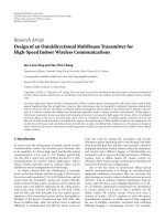
Figure 11 shows the die photo of the fresh chip and the
floorplan of the different IP blocks.
In this circuit, DART is intended to implement the chan-
nel estimation of the OFDM application. To achieve this
goal, we have integrated two division operators into the
application-specific area of the cluster. Memory hierarchy has
been modified to respond to the communication paradigm
of the used network. It integrates two FIFOs serving as a net-
work interface. All local memories are dual-port RAMs to
enable read/write accesses in the same cycle, while facilitat-
ing the design by avoiding multiphase clocks. Due to accu-
racy concerns, the cluster was modified to support 32 bits in
the datapath and in the local memories. These specific mod-
ifications had a significant impact on the power figures, but
they had increased the quality of the processing and simpli-
fied the chip design.
Including all the above modifications, the resulting
DART circuit presents a complexity of 2.4 M gates includ-
ing the whole memory hierarchy. Synthesis, place and route,
design check, and validation process have taken 108 hours.
The cluster requires a total power of 709mW, including a
100 mW leakage power. DART can run at a 200 MHz clock
frequency, and then it reaches 4800 MOPS for 32-bit opera-
tions and up to 9600 MOPS for 16-bit operations. These first
12 EURASIP Journal on Embedded Systems
Figure 11: The fresh circuit die photo including the DART IP.
Table 2: Characteristics of the DART IP.
Technology 0.13 μm CMOS from STMicrolectronics
Supply voltage 1.2 V
Die size 2.68 mm
× 8.3 mm
Clock frequency 200 MHz
Average total power 709 mW
Transistor count 2.4-million transistors
Computing performances 4800 MOPS on 32-bit data
9600 MOPS on 16-bit data
results confirm the energy efficiency of the proposed archi-
tecture.
9. CONCLUSIONS
In this paper, we have shown that functional-level recon-
figuration offers opportunities to improve energy efficiency
of flexible architectures. This level of reconfiguration allows
for the reduction of energy wastes in control by minimiz-
ing reconfiguration data volume. The coarse-grain paradigm
of computation optimizes storage as well as computation re-
sources from an energy point of view. The association of key
concepts and energy-aware design has led us to the defini-
tion of the DART architecture. This architecture deals con-
currently with high-performance, flexibility, and low-energy
constraints. We have validated this architecture by present-
ing implementation results coming from a WCDMA receiver
and demonstrated its potential in the context of multimedia
mobile computing applications. Finally, a chip was designed
and fabricated including a DART cluster to validate the con-
cept.
REFERENCES
[1] J. Fridman, “Sub-word parallelism in digital signal process-
ing,” IEEE Signal Processing Magazine, vol. 17, no. 2, pp. 27–35,
2000.
[2] J. P. Wittenburg, P. Pirsch, and G. Meyer, “A multithreaded ar-
chitecture approach to parallel DSPs for highperformance im-
age processing applications,” in Proceedings of the IEEE Work-
shop on Signal Processing Systems (SiPS ’99), pp. 241–250,
Taipei, Taiwan, October 1999.
[3] C. Steiger, H. Walder, and M. Platzner, “Operating systems for
reconfigurable embedded platforms: online scheduling of real-
time tasks,” IEEE Transactions on Computers, vol. 53, no. 11,
pp. 1393–1407, 2004.
[4] I. Brynjolfson and Z. Zilic, “FPGA clock management for low
power applications,” in Proceedings of the 8th ACM/SIGDA
International Symposium on Field Programmable Gate Arrays
(FPGA ’00), pp. 219–225, Monterey, Calif, USA, February
2000.
[5] H. Zhang, M. Wan, V. George, and J. Rabaey, “Interconnect
architecture exploration for low-energy reconfigurablesingle-
chip DSPs,” in Proceedings of the IEEE Computer Society Work-
shop On VLSI (VLSI ’99), pp. 2–8, Orlando, Fla, USA, April
1999.
[6] J. Villarreal, D. Suresh, G. Stitt, F. Vahid, and W. Najjar, “Im-
proving software performance with configurable logic,” Design
Automation for Embedded Systems, vol. 7, no. 4, pp. 325–339,
2002.
[7] R. Hartenstein, M. Herz, T. Hoffmann, and U. Nageldinger,
“Using the kressarray for reconfigurable computing,” in Con-
figurable Computing: Technology and Applications, vol. 3526
of Proceedings of SPIE, pp. 150–161, Bellingham, Wash, USA,
November 1998.
[8] C. Ebeling, D. Cronquist, and P. Franklin, “RaPiD—
reconfigurable pipelined datapath,” in Proceedings of the
6th International Workshop on Field-Programmable Logic,
Smart Applications, New Paradigms and Compilers (FPL ’96),
vol. 1142 of Lecture Notes in Computer Science, pp. 126–135,
Darmstadt, Germany, September 1996.
[9] E. Waingold, M. Taylor, D. Srikrishna, et al., “Baring it all to
software: raw machines,” Computer, vol. 30, no. 9, pp. 86–93,
1997.
[10] B. Salefski and L. Caglar, “Re-configurable computing in wire-
less,” in Proceedings of the 38th Conference on Design Automa-
tion (DAC ’01), pp. 178–183, Las Vegas, Nev, USA, June 2001.
[11] V. Baumgarte, G. Ehlers, F. May, A. N
¨
uckel, M. Vorbach, and
M. Weinhardt, “PACT XPP—a self-reconfigurable data pro-
cessing architecture,” The Journal of Supercomputing, vol. 26,
no. 2, pp. 167–184, 2003.
[12] M. Suzuki, Y. Hasegawa, Y. Yamada, et al., “Stream ap-
plications on the dynamically reconfigurable processor,” in
Proceedings of the IEEE International Conference on Field-
Programmable Technology (FPT ’04), pp. 137–144, Brisbane,
Australia, December 2004.
[13] A. Lodi, M. Toma, F. Campi, A. Cappelli,R.Canegallo,andR.
Guerrieri, “A VLIW processor with reconfigurable instruction
set for embedded applications,” IEEE Journal of Solid-State Cir-
cuits, vol. 38, no. 11, pp. 1876–1886, 2003.
[14] H. Zhang, V. Prabhu, V. George, et al., “A 1-V heterogeneous
reconfigurable DSP IC for wireless baseband digital signal pro-
cessing,” IEEE Journal of Solid-State Circuits, vol. 35, no. 11, pp.
1697–1704, 2000.
S
´
ebastien Pillement et al. 13
[15] V. George, Low energy field-programmable gate array,Ph.D.
thesis, University of California, Berkeley, San Diego, USA,
2000.
[16] R. David, D. Chillet, S. Pillement, and O. Sentieys, “DART:
a dynamically reconfigurable architecture dealing with future
mobile telecommunications constraints,” in Proceedings of the
16th International Parallel and Distributed Processing Sympo-
sium (IPDPS ’02), pp. 156–163, Fort Lauderdale, Fla, USA,
April 2002.
[17] H. Meier, Analysis and design of low power digital multipliers,
Ph.D. thesis, Carnegie Mellon University, Pittsburgh, Pa, USA,
August 1999.
[18] M. D. Ercegovac and T. Lang, Digital Arithmetic,Morgan
Kaufmann, San Francisco, Calif, USA, 2004.
[19] R. David, D. Chillet, S. Pillement, and O. Sentieys, “A com-
pilation framework for a dynamically reconfigurable archi-
tecture,” in Proceedings of 12th International Conference on
the Reconfigurable Computing is Going Mainstream, Field-
Programmable Logic and Applications, vol. 2438 of Lecture
Notes in Computer Science, pp. 1058–1067, Springer, Montpel-
lier, France, September 2002.
[20] R. Schreiber, S. Aditya, S. Mahlke, et al., “PICO-NPA: high-
level synthesis of non programmable hardware accelerators,”
Tech. Rep. HPL-2001-249, Hewlett-Packard Labortories, Palo
Alto, Calif, USA, 2001.
[21] D. Nicklin, “Wireless base-station signal processing with a
platform FPGA,” in Proceedings of the Wireless Design Confer-
ence, London, UK, May 2002.
[22] J. R. Hauser, Augmenting a microprocessor with reconfigurable
hardware, Ph.D. thesis, University of California, Berkeley, San
Diego, USA, 2000.
[23] R. P. Wilson, R. S. French, C. S. Wilson, et al., “SUIF: an infras-
tructure for research on parallelizing and optimizing compil-
ers,” Tech. Rep., Computer Systems Laboratory, Stanford Uni-
versity, Stanford, Calif, USA, May 1994.
[24] A. Fraboulet, K. Kodary, and A. Mignotte, “Loop fusion for
memory space optimization,” in Proceedings of the 14th Inter-
national Symposium on Systems Synthesis (ISSS ’01), pp. 95–
100, Montreal, Canada, September-October 2001.
[25] A. Fraboulet, G. Huard, and A. Mignotte, “Loop alignment
for memory accesses optimization,” in Proceedings of the 12th
International Symposium on System Synthesis (ISSS ’99),p.71,
San Jose, Calif, USA, November 1999.
[26] F. Charot and V. Messe, “A flexible code generation frame-
work for the design of application specific programmable pro-
cessors,” in Proceedings of the 17th Internat ional Workshop on
Hardware/Software Codesign (CODES ’99), pp. 27–31, Rome,
Italy, May 1999.
[27] T. Ojanpera and R. Prasad, Wideband CDMA for Third Gener-
ation Mobile Communications, Artech House, Norwood, Mass,
USA, 1998.
[28] E. H. Dinan and B. Jabbari, “Spreading codes for direct se-
quence CDMA and wideband CDMA cellular networks,” IEEE
Communications Magazine, vol. 36, no. 9, pp. 48–54, 1998.
[29] Texas instruments, “TMS320C64x technical overview,” Tex a s
instruments, February 2000.
[30] Y. Durand, C. Bernard, and D. Lattard, “FAUST: on-chip dis-
tributed architecture for a 4G baseband modem SoC,” in Pro-
ceedings of Design and Reuse (IP-SOC ’05), pp. 51–55, Greno-
ble, France, December 2005.
[31] PACT, “The XPP white paper : a technical perspective,” Release
2.1, PACT, March 2002.
[32] E. Beign
´
e, F. Clermidy, P. Vivet, A. Clouard, and M. Renaudin,
“An asynchronous NOC architecture providing low latency
service and its multi-level design framework,” in Proceedings
of the 11th IEEE International Symposium on Asynchronous
Circuits and Systems (ASYNC ’05), pp. 54–63, New York, NY,
USA, March 2005.