Báo cáo hóa học: " Research Article LDPC Code Design for Nonuniform Power-Line Channels" pptx
Bạn đang xem bản rút gọn của tài liệu. Xem và tải ngay bản đầy đủ của tài liệu tại đây (816.33 KB, 9 trang )
Hindawi Publishing Corporation
EURASIP Journal on Advances in Signal Processing
Volume 2007, Article ID 76146, 9 pages
doi:10.1155/2007/76146
Research Article
LDPC Code Design for Nonuniform Power-Line Channels
Ali Sanaei and Masoud Ardakani
Department of Electrical and Computer Engineering, Faculty of Engineering, University of Alberta, Edmonton,
AB, Canada T6G 2V4
Received 28 October 2006; Revised 8 March 2007; Accepted 1 May 2007
Recommended by Lutz Lampe
We investigate low-density parity-check code design for discrete multitone channels over power lines. Discrete multitone channels
are well modeled as nonuniform channels, that is, different bits experience v arious channel parameters. We propose a coding sys-
tem for discrete multitone channels that allows for using a single code over a nonuniform channel. The number of code parameters
for the proposed system is much greater than the number of code parameters in conventional channel. Therefore, search-based op-
timization methods are impractical. We first formulate the problem of optimizing the rate of an irregular low-density parity-check
code, with guaranteed convergence over a general nonuniform channel, as an iterative linear programming which is significantly
more efficient than search-based methods. Then we use this technique for a typical power-line channel. The methodology of this
paper is directly applicable to all decoding algorithms for which a density evolution analysis is possible.
Copyright © 2007 A. Sanaei and M. Ardakani. This is an open access article distributed under the Creative Commons Attribution
License, which permits unrestricted use, distribution, and reproduction in any medium, provided the original work is properly
cited.
1. INTRODUCTION
Discrete multitone (DMT) modulation is widely used in
power-line communications. DMT modulation is almost al-
ways used in conjunction with channel coding, which is
called coded DMT. In the past few years, some of the modern
coding techniques such as low-density parity-check (LDPC)
coding and turbo coding are proposed for coded DMT sys-
tems [1–5]. The motivation for using these codes has been
their phenomenal performance with practical complexity.
In previous works on applying turbo and LDPC codes to
power-line and general DMT channels, the channel is usually
assumed to be uniform over all frequency tones. In practice,
however, the channel SNR varies from one frequency tone
to another. That is to say, if all the frequency tones are as-
signed to a single binary code, different bits of the codeword
are received with different qualities at the receiver. This can
seriously harm the iterative decoding process.
The method proposed in [5] mitigates the effects of
nonuniformity in the DMT channels by using QAM constel-
lations of possibly different sizes in different frequency tones.
The size of the QAM constellation is selected according to
the SNR of the tone. Then a certain number of least signif-
icant bits from each QAM constellation (2 bits in this case)
are Gray labeled and all higher bits are Ungerboeck labeled.
The Gray-labeled bits are then assigned to a binary LDPC
code. The Ungerboeck-labeled bits are coded separately with
other codes (hence they do not contribute to the length of
the LDPC code). The reason for using constellations of dif-
ferent sizes and using Gray labeling is to obtain equivalent
bit-channels that have similar quality. This way, they can be
assigned to a single LDPC code.
Although high coding gains are reported in [5], the pro-
posed technique has some down sides. First, it does not use a
single code for all the bits and only two bits of each constella-
tion size are assigned to the LDPC code. Therefore, the maxi-
mum possible code length for a given tolerable buffer delay is
not used. Using different codes for Ungerboeck-labeled bits
also increases the system complexity. Moreover, using many
different constellation sizes may not be an attractive solution
for systems that cannot tolerate the required signalling and
detection complexity.
If constellations of different sizes could not be used, the
quality of the soft information at the receiver can signifi-
cantly vary from one frequency tone to another. Thus, one
has to consider the nonuniformity of the channel in the code
design process.
A nonuniform DMT channel can be modeled as a num-
ber of parallel uniform channels (referred to as subchannels
in the remainder of this paper). The transmission of a code-
word, therefore, can be thought as transmission of bits over
these parallel subchannels. Thus, some of the bits of the code-
word are received with a good quality at the receiver and
some are received with a poor quality. All the bits, however,
2 EURASIP Journal on Advances in Signal Processing
are decoded together in a single LDPC code decoder. The
code is designed w i th a perfect knowledge of the parallel sub-
channels and the portion of bits that are passed through each
subchannel.
The problem of LDPC coding for parallel channels is
studied in [6]. The central observation is that by breaking the
variable node degree distribution of an LDPC code to sub-
degree distributions, LDPC codes can be designed for par-
allel channels. That is to say, the degree distribution defines
the fraction of edges connected to variable nodes of different
degreesattheoutputofdifferent subchannels. We call this
solution allotted LDPC coding in contrast with conventional
LDPC coding. Apparently, in order to employ allotted codes,
one needs channel state information at the transmitter side.
The number of design parameters is significantly in-
creased for allotted LDPC codes. Thus, a design method,
which is primarily based on a search in the space of the de-
sign parameters, would be quite inefficient [7]. To tackle this
problem, the authors of [6] propose semiregular codes where
the output of each subchannel is assigned to nodes of one
degree. This notably reduces the search space, but unfortu-
nately may not result in the optimal solution.
In this work, we show that the problem of designing
irregular LDPC codes for parallel channels can be solved
by iterative linear programming (LP). Hence, an efficient
global optimization of the degree distribution is made pos-
sible without limiting ourselves to semiregular codes. Since
semiregular codes are special cases of irregular codes, irregu-
lar codes can only do better than semiregular codes. It should
be noted that LP has already been proposed for designing
conventional LDPC codes [8, 9]. The extension to nonuni-
form channels requires new considerations that will be dis-
cussed in the sequel.
In this work, after formulating code design as an itera-
tive LP, we propose a system structure and coding solution
for DMT channels that are encountered in power-line com-
munications. We then perform code design according to the
iterative LP approach and compare the performance of our
codes with conventional codes which are optimized for the
same channel. Although our primary focus is on DMT chan-
nels for power-lines, the code optimization method is pre-
sented in a general setup. So, the method can directly be ap-
plied to other systems with nonuniform channels.
This paper is organized as follows. In Section 2,webriefly
review the required background of nonuniform channels
and LDPC coding for uniform and nonunifor m channels.
Section 3 discusses the channel model. In Section 4, the code
design technique is discussed. Section 5 presents the overall
structure of the coded DMT system based on LDPC cod-
ing for parallel channels. A numerical example for a typical
power-line channel is also presented in this section. Finally,
Section 6 concludes the paper.
2. BACKGROUND
2.1. Coding over nonuniform channels
There has been much work on the design of codes over dif-
ferent channel models. It is usually assumed that the chan-
nel is u niform, that is, all the transmitted bits experience the
same channel parameters. However, many communication
systems can be modeled as a group of parallel subchannels
with different qualities. Therefore, different transmitted bits
may experience different channel parameters. For example, a
DMT system consists of different frequency tones that each
has its own SNR.
The model we use in this work for a nonuniform chan-
nel is a channel made up of K parallel subchannels. sub-
channels have independent statistical behaviour and they are
isolated, that is, data passing through one subchannel does
not affect other subchannels. The number of bits that pass
through each subchannel in every channel use can be differ-
ent. Usually this number is dictated by the signaling used for
subchannels. The signaling may be chosen according to the
capacity of subchannels, which is called bit loading.
The most basic coding scheme is to use separate codes for
the data transmitted over different subchannels. The main
benefit of this approach is that if the capacity of each sub-
channel is achieved by its corresponding code, then the over-
all capacity of the channel is achieved. However, capacity
approaching codes, such as LDPC codes, can appr oach the
capacity only at very long block lengths. When one long
code is used for each subchannel, the buffer fill delay will
be intolerable for delay-sensitive applications. Moreover, this
method requires separate encoders/decoders for each sub-
channel which adds to the complexity of the system.
Therefore, a solution that utilizes one single code for all
of the subchannels is more attractive. T he problem is that dif-
ferent parts of the codeword go through different subchan-
nels with different qualities. Nevertheless, the existing knowl-
edge about the quality of subchannels may be used in both
the code design process and during the encoding/decoding
in order to allow for near-capacity performance. The main
challenge is to take this knowledge into consideration in the
design process.
2.2. LDPC coding
Among different channel coding methods, low-density
parity -check (LDPC) coding [10] has been considered the
most powerful one. This family of codes can achieve the
capacity of the binary erasure channel (BEC) [11]andcan
approach the capacity of many other channel models [12].
LDPC coding is also attractive because of the flexibility of
code parameters.
Conventional irregular LDPC codes, in the simplest
form, are characterized by their variable node and check
node degree distributions [13].Thevariablenodedegreedis-
tribution is usually denoted by λ
={λ
2
, λ
3
, },whereλ
i
is the fraction of edges in the Tanner graph [14] (or factor
graph [15]) of the code, incident to variable nodes of degree
i. Similarly, the check node degree distribution is denoted by
ρ
={ρ
2
, ρ
3
, }. The decoding of LDPC codes is based on
iterative message passing on the Tanner g raph. Each message
is a belief about the adjacent variable node.
When the code length is large, the performance of an
LDPC code on a given channel is only a function of λ and
A. Sanaei and M. Ardakani 3
ρ [7]. Using a technique called density evolution [16], one
can study whether or not a degree distribution can clear er-
rors introduced by a given channel. Therefore, by LDPC code
design we usually mean finding a variable node and a check
node degree distribution which optimizes an objective func-
tion, while guaranteeing convergence to a target error rate
[7].
It is shown that fixing ρ (and in many cases putting all the
weight on one degree) and optimizing λ is an effective design
method without considerable performance degradation [11,
16]. This way the design parameters are λ
i
’s. Optimization of
ρ has also been considered in the literature [17].
Decoding of LDPC codes is based on message passing. A
message is a belief about the value of the adjacent bit in the
graph of the code. Usually the messages that are passed on
the edges of the g raph of the code are log-likelihood ratios
(LLR). If bit x is sent and y is received, the LLR is
LLR
= log
p(x
= 0 | y)
p(x = 1 | y)
. (1)
Since densit y evolution is based on the assumption that all-
zero codeword is tr ansmitted, the negative tail of the den-
sity of LLR shows the fraction of messages that are carrying a
wrong belief. This means that the negative tail of the density
is equal to message error rate.
The problem of LDPC code design for nonuniform chan-
nel has been studied in [6, 18, 19]. The main idea is that be-
cause different subchannels have different qualities, in order
to use a single code for all bits, one should specify which bits
of the codeword are sent through each subchannel. In the
context of LDPC codes, one way to do this allotment, as [6]
suggests, is to break the variable node degree distribution of
an LDPC code to subdegree distributions. In other words, the
degree distribution specifies the fraction of edges connected
to variable nodes of different degrees at various subchannels,
that is, Λ
={Λ
( j)
i
, },whereΛ
( j)
i
is the fraction of edges that
are connected to variable nodes of degree i that are transmit-
ted via subchannel j. Notice that Λ can be shown by a matrix
whose different rows represent degree distribution for differ-
ent subchannels, whereas λ is a vector.
Allotted codes become more appealing when the quality
of subchannels varies over a broad range. This is the case for
data communication over power-lines.
3. CHANNEL MODEL AND SIGNALLING
The channel model used is a set of K parallel memoryless
subchannels with different parameters. Subchannels can be
specified by their conditional probabilities. Suppose symbol
X is transmitted over subchannel j,1
≤ j ≤ K, the probabil-
ity density function (pdf) of receiving Y, that is, P
j
(Y | X)
defines subchannel j. Also, suppose that subchannel j car-
ries γ
j
fraction of bits. That is, if the whole channel carries
N coded bits in every channel use, γ
j
N bits are to be sent
through subchannel j and
i
γ
j
= 1.
3.1. Signalling
DMT channels that are encountered in power-line commu-
nications usually have frequency tones within a broad range
of quality. In order to make use of the subchannels with good
quality, higher order modulations should be employed. Ca-
pacityapproachingcodessuchasturbocodesandLDPC
codes, however, are more attr active when used as binary
codes. This is because the decoding complexity increases ex-
ponentially with the alphabet size of the code. A possible so-
lution is to employ multilevel coding which allows for using
binary codes with nonbinary modulations.
The idea of multilevel coding [20, 21] is that for a non-
binary constellation A
={a
0
, a
1
, , a
M−1
} of M = 2
l
, l>1,
points, constellation points can be labeled with l-bit binary
sequences (b
0
, b
1
, , b
l−1
). A binary code can then be used
to protect these address bits.
There is a one-to-one mapping between address bits and
the constellation points. This means that the mutual infor-
mation between received and transmitted signals is the same
as the mutual information between the received signal and
address bits of the transmitted signal. Suppose A and Y rep-
resent the random variables corresponding to the transmit-
ted and received signals, respectively, and (B
0
, B
1
, , B
l−1
)is
the vector random variable representing the address vector.
We have
I(Y; A)
= I
Y; B
0
, B
1
, , B
l−1
. (2)
Equivalently, we have
I(Y; A) = I
Y; B
0
, B
1
, , B
l−1
=
I
Y; B
0
+ I
Y; B
1
| B
0
+ ···
+ I
Y; B
l−1
| B
0
, B
1
, , B
l−2
).
(3)
In other words, transmission of a symbol a
i
∈ A, i =
0, 1, , M − 1, is equivalent to the transmission of a binary
address (b
0
, b
1
, , b
l−1
) ∈ b, which in turn can be thought
as separated transmission of individual bits.
One multilevel coding solution is based on considering
every term in the right hand side of (3)asanequivalentbit-
channel [21]. This would require sequential decoding of bits.
The capacity of different bit-channels depends on the la-
beling scheme, and these bit-channel capacities can be signif-
icantly different from one another [22]. However, when Gray
labeling is used, these capacities are very close [23]. More im-
portantly, as shown in [23], if Gray labeling is used, one can
interleave (b
0
, , b
l−1
) and decode them together—and not
sequentially. Since the bits are not decoded sequentially, one
code can be used for all of them. This technique is called bit-
interleaved coded modulation (BICM) which has a perfor-
mance almost identical to multilevel coding at high SNR.
On a nonuniform channel, even if BICM is adopted, the
problem of nonuniform quality of bit-channels is not fully
resolved. Although BICM, for a particular frequency tone,
results in bit-channels that have almost equal capacity, the
bit-channel capacity may still significantly vary from one fre-
quency tone to another due to the varying SNR of different
4 EURASIP Journal on Advances in Signal Processing
frequency tones. Therefore, transmission of a DMT symbol
over a frequency selective channel has to be modeled as trans-
mission of bits over parallel channels whose capacities are not
equal. Adopting BICM is still practically important, because
it removes a need for sequential decoding and allows for us-
ing a single code. In Section 5, when we propose a system
structure for data tr ansmission on power-line channels, we
use BICM.
Note that when BICM is employed, the channel may not
be symmetric. Nevertheless, density evolution is possible in
the following way [24]. One can transmit all different sig-
nals on the constellation, but when LLRs are calculated, the
sign of the LLR corresponding to bits whose original value
has been 1 should be inverted. This way, from the point of
view of the LDPC code (and only for the purpose of density
evolution and not actual decoding), the all-zero codeword is
transmitted. This allows for a valid all-zero assumption in
density evolution.
3.2. Bit-channels
Once the signalling is specified, without loss of generality,
instead of dealing with K subchannel, we can use the cor-
responding bit-channels [20]. There are N bit-channels with
possibly different qualities. In fac t, since every variable node
in the Tanner graph represents one bit, it is more convenient
to use bit-channels instead of the actual subchannels.
The large number of bit-channels, however, increases the
complexity of design and system in general. To avoid this,
one can group bit-channels according to their capacity into
K
groups (K
N). Note that from the code design per-
spective, there is no difference between the actual subchan-
nels and the groups of bit-channels. Therefore, in the sequel,
K is always used as one of the dimensions of desig n parame-
ters, whether it shows the number of subchannels or it shows
the number of groups of bit-channels.
4. CODE DESIGN
We consider transmission of N LDPC-coded bits (N
→∞)
over K independent subchannels, where subchannel j,1
≤
j ≤ K, passes γ
j
fraction of the bits. That is, if the code length
is N bits, γ
j
N bits of every codeword go through subchannel
j. The goal is to find the irregular LDPC code which achieves
the highest rate of data transmission over this channel.
As stated earlier, density evolution is a technique for an-
alyzing LDPC codes. The task of density evolution algorithm
is to track the evolution of the probability density function
of extrinsic messages in the decoder iteration by iteration.
Whenever the density of extrinsic messages in the decoder is
completely describable by a single parameter, we say the de-
coding algorithm is one dimensional, otherwise, we say the
decoding algorithm is multidimensional. As we will see, the
design procedure is simpler for one-dimensional decoding
algorithms. For many practical purposes, however, neither
an exact nor an acceptable approximate one-dimensional de-
scription of the decoder is available and those cases have to
be dealt with separately.
In this work, first, assuming that an exact one-dimen-
sional description of the decoder is possible, we show that the
code design problem can be solved through an iterative LP
approach. Then, we modify our method to allow for an LP-
based code design for the general case of multidimensional
decoder.
4.1. One-dimensional decoders
When the density of extrinsic messages in the decoder can be
described by a single parameter, for example, when a Gaus-
sian approximation is used [25], density evolution is simpli-
fied to tracking the evolution of that single parameter. More-
over, density evolution is based on the assumption that the
all-zero codeword is transmitted, so an error rate can be as-
sociated to the decoders extrinsic messages [7]. Therefore,
tracking the evolution of the message error rate iteration by
iteration is equivalent to density evolution. The main benefit
of tracking the message error rate is that the message error
rate at the output of variable nodes, p
out
,canbewrittenas
p
out
=
i
j
Λ
( j)
i
· p
( j)
out,i
,(4)
where p
( j)
out,i
is the message error rate at the output of degree
i nodes that are assigned to subchannel j. Notice that p
( j)
out,i
is
a func tion of the message error rate at the input of the itera-
tion, p
in
. Also, notice that p
in
is the same for all nodes as the
structure of the LDPC code interleaves all the messages f rom
the previous iteration. Therefore, we rewrite (4)as
p
out
p
in
=
i
j
Λ
( j)
i
· p
( j)
out,i
p
in
. (5)
For every p
in
, fixing the check degree distribution, one
can find p
( j)
out,i
(p
in
)fordifferent values of i. Hence, the task of
code design is to find Λ
( j)
i
’s that result in the maximum-rate
code for which convergence to zero error rate is guaranteed.
That is,
p
out
p
in
<p
in
, ∀p
in
∈
0, p
0
. (6)
Here, p
0
is the initial message error rate dictated by the chan-
nel quality. This means that after each iteration of decod-
ing, the number of errors should be decreased. Typically,
the number of design parameters can be K times more than
the case of conventional LDPC codes, making a search-based
code design practically infeasible.
The rate of the code in terms of its degree distr ibution is
R
= 1 −
i
ρ
i
/i
i
j
Λ
( j)
i
/i
. (7)
A. Sanaei and M. Ardakani 5
Since, the check degree distribution is fixed and the design
parameters are Λ
( j)
i
’s, maximizing the code rate is equivalent
to maximizing
i
j
Λ
( j)
i
i
. (8)
Notice that this is a linear function of the design para meters.
There are a number of constraints on the design parame-
ters as follows. The first constraint is for all i, j, Λ
( j)
i
≥ 0. The
second constraint is
i
j
Λ
( j)
i
= 1. In addition, since γ
j
is the fraction of nodes assigned to channel j, another con-
straint comes into play. To formulate this constraint, let us
assume that there are E edges in the factor graph of the code.
The number of degree i nodes connected to channel j is then
N
( j)
i
=
Λ
( j)
i
· E
i
. (9)
Therefore, the total number of nodes connected to channel j
is
N
( j)
=
i
Λ
( j)
i
· E
i
, (10)
and the total number of nodes (code length) is
N
=
i
j
Λ
( j)
i
· E
i
. (11)
The number of nodes connected to channel j should form γ
j
fraction of the code length, hence,
i
Λ
( j)
i
· E
i
− γ
j
i
j
Λ
( j)
i
· E
i
= 0, ∀ j,1≤ j ≤ K.
(12)
Now it is possible to eliminate E and form the following K
linear constraint on Λ
( j)
i
’s:
i
Λ
( j)
i
i
− γ
j
i
j
Λ
( j)
i
i
= 0, ∀ j,1≤ j ≤ K. (13)
It is not hard to see that out of this K constraints, a maximum
of K
− 1 of them can be linearly independent.
Moreover, since convergence to zero error rate has to be
guaranteed, (6) is another constraint to be satisfied. Using
(5), we need
i
j
Λ
( j)
i
p
( j)
out,i
p
in
<p
in
, (14)
which is another linear constraint. In practice, since we want
to have finite number of constraints, the latter constraint
cannot be forced for all continuous values of p
in
, but usually
a finite set of p
in
’s serves the purpose of design [13].
All the constraints are linear functions of the design pa-
rameters (essential for an LP formulation of the problem).
However, there is a minor difficulty with this formulation.
In a conventional channel, we require p
out
<p
in
for all
p
in
∈ (0, p
0
], where p
0
is the intrinsic message error rate (the
channel error rate), and is independent of the code. This is
because, at the first iteration, all the variable nodes propa-
gate the channel observation on their incident edges. Hence,
the error rate of the decoder messages is initially equal to p
0
.
In the case of nonuniform channels, no unique p
0
is defined.
In fact, the initial decoder message error rate, p
∗
0
, is also af-
fected by the degree distr ibution of the code. To see why, no-
tice that if a variable node of degree i is assigned to subchan-
nel j, immediately (at the beginning of the iterative decod-
ing), the output of this subchannel is copied over i edges. So
the message error rate of these i edges depends on the pa-
rameters of channel j. It is evident here that p
∗
0
in the case of
nonuniform channels is a function of Λ
( j)
i
’s.
4.2. Solution strategy
The objective function as well as all the constraints are linear
functions of the design parameters. But the problem cannot
be cast as an LP because p
∗
0
is not independent of Λ
( j)
i
’s.
For the sake of clarification of the details, we write the op-
timization problem for the case of K BEC with erasure rates
p
1
to p
K
under belief propagation similar to a standard LP.
For a check degree distribution ρ
={ρ
2
, ρ
3
, },wedefine
ρ(x)
=
i
ρ
i
x
i−1
. It can be seen [11] that if the message era-
sure rate at the input of check nodes is p
in
after check node
operations, the erasure error rate is
p
ch
= 1 − ρ
1 − p
in
. (15)
Therefore, at the output of a degree i variable node connected
to subchannel j, the erasure error rate is
p
( j)
out,i
= p
j
·
1 − ρ
1 − p
in
i−1
. (16)
Hence, the optimization can be formulated as
maximize
D
v
i=2
K
j=1
Λ
( j)
i
i
subject to
∀i, j, Λ
( j)
i
≥ 0,
D
v
i=2
K
j=1
Λ
( j)
i
= 1,
∀ j,
D
v
i=2
Λ
( j)
i
i
− γ
j
D
v
i=2
K
j=1
Λ
( j)
i
i
= 0,
∀p
in
∈
0, p
∗
0
,
D
v
i=2
K
j=1
Λ
( j)
i
p
j
1 − ρ
1 − p
in
i−1
<p
in
.
(17)
Here, D
v
is the maximum variable node degree allowed in the
code and p
∗
0
is the initial message erasure rate which can be
6 EURASIP Journal on Advances in Signal Processing
computed as
p
∗
0
=
i
j
Λ
( j)
i
· p
j
. (18)
One strategy for solving this optimization problem is to
overlook the dependency of p
∗
0
on the design parameters;
start with some approximation of p
∗
0
, solve the problem as if
it is an LP, and after finding the optimum Λ
( j)
i
’s, update p
∗
0
.
Now, we can solve the problem with the updated p
∗
0
again.
If the solution is not very sensitive to p
∗
0
, this approach will
converge in only a few rounds. This is because the change
in p
∗
0
only adds or removes a few constraints and most of the
constraints in the LP remain unchanged. In fact, experiments
show that this is a very effective method and in many cases it
requires only a couple of rounds of LP.
Similar formulation can be done for other one-dimen-
sional decoding algorithms. The only difference will be in the
relation between p
in
and p
( j)
out,i
(p
in
).
4.3. Multidimensional decoding algorithms
There are cases for which density evolution cannot be simpli-
fied to the evolution of a single parameter. In other words, the
decoding algorithm is not one dimensional. In s ome cases, a
one-dimensional approximate analysis is acceptable. Clearly,
in such cases, our methodology is applicable without any
changes. If a one-dimensional approximation is not accurate
enough, however, one can still formulate the problem as an
LP.
To see how this works, notice that after performing n it-
erations of density evolution, it is possible to visualize the
convergence behavior of the decoder by plotting the message
error rate of iteration m, m
∈{1,2, , n}, versus the mes-
sage error rate of iteration m
− 1. This gives p
out
as a function
of p
in
, in a set of n discrete points. Recall that in the LP for-
mulation, we need p
( j)
out,i
(p
in
) at a discrete set of points. Any
iteration of density evolution defines a unique p
in
and also
gives the density of messages at the output of degree i nodes
of subchannel j. As a result, p
( j)
out,i
(p
in
), which is the negative
tail of the density, can be computed. Therefore, p
( j)
out,i
(p
in
)is
known at n values of p
in
. Hence, one can run the LP using
this n values of p
in
, or can use interpolation to add interme-
diate points to the set of p
in
’s.
There is only one minor technical problem which should
be addressed. The value of p
( j)
out,i
(p
in
) is itself a function of
the design parameters Λ
( j)
i
. In other words, p
out
is affected by
any Λ
( j)
i
in two ways. Once, like previous case, through the
linear combination of (5) as a multiplying factor and also
through the direct effect of Λ
( j)
i
in p
( j)
out,i
(p
in
). For conven-
tional channels, it is shown in [26] that the direct effect of de-
gree distribution on p
out
is much less than the effect through
(5). Therefore, one can overlook dependency of p
( j)
out,i
(p
in
)on
Λ
( j)
i
’s when Λ
( j)
i
’s undergo a small change.
Hence the problem can be cast as an LP if the changes
made in Λ
( j)
i
’s are small. This constraint can be imposed in
various ways, but we are only interested in linear constraints.
The simplest way is to guaranty that every Λ
( j)
i
changes
smaller than a certain value
. So, if the value of the design
parameters is Λ
∗
, we have the foll owing set of constraints for
every element of Λ:
Λ
( j)
i
≤ (1 + ) Λ
( j)
∗
i
,
Λ
( j)
i
≥ (1 − ) Λ
( j)
∗
i
.
(19)
This will add K
× D
v
new constraints. Using the inner
product of the current and previous values is a slightly s im-
pler way to make sure that Λ
( j)
i
’s will change as small as we
want. Let us define Λ as a vector whose entries are Λ
( j)
i
’s
in some order. Also consider another vector Λ
∗
,andas-
sume that we want Λ to be close to Λ
∗
. We also assume that
Λ≈Λ
∗
, which is a valid assumption if Λ and Λ
∗
are
close to each other. If θ is the angle between these two vec-
tors, we w ant cos(θ)
≈ 1, or in other words, for some small
> 0wewant
Λ, Λ
∗
≥Λ
Λ
∗
(1 − ), (20)
where
·, · is the inner product of two vectors and is defined
as
i
j
Λ
( j)
i
Λ
( j)
∗
i
. Therefore, for a given Λ
∗
and we have
i
j
Λ
( j)
i
Λ
( j)
∗
i
≥
Λ
∗
2
(1 − ), (21)
which is a linear constraint in Λ
( j)
i
’s.
If
is very smal l, we need to repeat the LP quite a num-
ber of times, to find the optimum Λ.Oneefficient approach
is to choose larger
’s and change them whenever the result
is a code whose density evolution does not converge to the
objective error rate.
Finally, it has to be pointed out that similar method could
be used to optimize ρ. It is only needed to tr ack the error
probability at the output of check nodes rather than variable
nodes. This, however, will not make a considerable difference
because the degradation caused by a carefully chosen regular
ρ is negligible.
4.4. Example
To show how the proposed algorithm works, a simple exam-
ple of a BEC is solved here. Consider data transmission over
two binary erasure subchannels with p
1
= 0.2andp
2
= 0.4
and assume γ
1
= 0.5andγ
2
= 0.5. We seek the highest-
rate LDPC code which achieves convergence over this chan-
nelwithamaximumnodedegreeof10inthecode.
For the initial value of p
∗
0
,weusep
∗
0
=
j
γ
j
p
j
.Thisre-
flects the average error (erasure) rate on the variable nodes,
which can be a reasonable initial estimate of the error (era-
sure) rate on the edges. After finding the optimum Λ
( j)
i
’s for
this p
∗
0
,wefindtheactualvalueofp
∗
0
using (18), and repeat
the procedure as discussed before. In fact, since Λ
( j)
i
’s are not
very sensitive to p
∗
0
, only two iterations of LP are required to
obtain the optimum code.
A. Sanaei and M. Ardakani 7
The results of the optimization program a re Λ
(1)
2
=
0.3228, Λ
(2)
2
= 0.1135, Λ
(2)
3
= 0.1207, Λ
(2)
4
= 0.1342, Λ
(2)
10
=
0.3088, and d
c
= 10 with a rate of R = 0.6902. The capacity
of this channel is C
= 0.7. Therefore, with this simple code,
98.6% of the capacity is achieved.
5. SYSTEM DESIGN FOR POWER-LINE CHANNELS
In this section, first we describe the overall structure of an
LDPC coded DMT over power-line, and then perform LDPC
code optimization. We also design a conventional LDPC code
to show the improvement obtained by optimized allotted
LDPC codes.
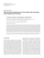
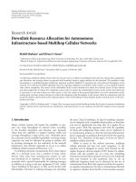
The overall structure of the coding system is shown in
Figure 1. The LDPC encoder takes R
· N bits from the source
and produces N coded bits regardless of the nonuniformity
of the channel. Here R is the code rate. The N coded bits
are then broken to N/l sequences. Each sequence has l bits
and represents one of the 2
l
points of a QAM constellation.
These N/l sequences are assigned to equivalent bit-channels
according to Λ.
Once all the binary sequences for all tones are ready, each
binary sequence is mapped to a complex symbol (accord-
ing to the labeling scheme), and using inverse fast Fourier
transform (IFFT), a DMT symbol is created. Notice that
one LDPC codeword may consist of multiple DMT symbols.
Since the number of bits in a DMT symbol depends on the
channel realization, the length of the LDPC may not be an
integer multiple of DMT symbols. However, the code block
length N is usually much larger than the number of bits in
one DMT symbol. Therefore, one can fill the LDPC code-
word with as many as possible DMT symbols and fill the re-
mainder of the codeword with zeros.
At the receiver, this process is reversed. When the LLR
value for every bit of the codeword is computed, the decoding
process starts. Similar to the encoding, the decoding is also
independent of the nonuniform channel. Hence, no modifi-
cation on the decoder and the encoder of the code is required.
There are many iterative decoding algorithms available
for LDPC codes. Sum-product decoding is the most accu-
rate one. Althoug h in the next sec tion we optimize the LDPC
code under sum-product decoding, our methodology based
on the proposed recursive LP is quite general and can be ap-
plied to any decoding algorithm for which a density evolu-
tion analysis [16] is possible.
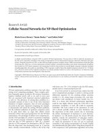
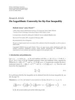
We use the channel model proposed in [27]forpower-
line communication and 64-QAM constellation for all tones.
The distribution of SNR in different tones is shown in
Figure 2. Note that the effects of impulse noise are neglected
here. While the channel model of [27] considers water filling,
it has to be mentioned that water filling does not affect our
approach as the coding solution is based on the channel SNR
distribution.
In order to avoid bit-channels with a very low capac-
ity, tones that have an SNR less than a threshold should
carry no information. For 64-QAM signalling, we may de-
cide not to use any tone with an SNR less than 1.2 dB. This
way, there will be no bit-channel with a capacity less than
0.2 bits/symbol.
This approach has minor effect on the overall perfor-
mance of the system, because low-capacity bit-channels have
minor effect on the overall capacity of the system. Moreover,
since the signal energy in these frequency tones can be re-
duced to zero, the signal energy in active frequency tones can
be increased. This approach is employed just to reduce the
overall complexity. For example, instead of having 1000 bit-
channels with average capacity of 0.42, we would rather have
800 bit-channels with average capacity of 0.5. This leads to a
considerable reduction of complexity with a slight degrada-
tion. It should be emphasized that even without this consid-
eration, the proposed coding solution works perfectly.
Since the number of active tones is relatively large, if
K (the number of parallel subchannels) is relatively small,
one can expect an average behavior in almost all channel re-
alizations. Therefore, the coding solution will be robust to
changes in the channel as long as K
(number of active
frequency tones).
We us e K
= 4 and the capacity ranges for subchannels
are selected to be [0.2, 0.4), [0.4, 0.6), [0.6, 0.8), and [0.8, 1).
On a 64-QAM signalling, these capacity ranges map to the
following SNR ranges, respectively, [1.2 dB, 6.5 dB), [6.5 dB,
10.8 dB), [10.8 dB, 14.8 dB), and [14.8 dB, +
∞). From the
distribution of the SNR (Figure 2), it can be easily found that
γ
1
= 0.3364, γ
2
= 0.2949, γ
3
= 0.2022, and γ
4
= 0.1665.
When the channel condition, the constellation size, and
the labeling scheme are known, the density of LLR messages
of the channel can be found via Monte Carlo simulation. This
provides an accurate analysis for a DMT system whose fre-
quency tones a re distributed according to the typical distri-
bution depicted in Figure 2. Then LLR distribution is used in
density evolution.
All of the codes in this section are designed so that they
converge to target error rate of 10
−7
in less than 400 iterations
of sum-product decoding with 11-bit precision. The effect
of 11-bit decoding and 400 iterations is in implementation
of “discrete density evolution” [12]. Choice of 400 iterations
and 11-bit decoding is arbitrary and the approaches of this
work are readily applicable to other numbers if needed.
Allowing a maximum node degree of 10 in the code, the
optimized degree distribution for this channel is ρ
={ρ
8
=
1} and Λ ={Λ
1
2
= 0.0058, Λ
1
3
= 0.1794, Λ
1
10
= 0.2003, Λ
2
2
=
0.1449, Λ
3
2
= 0.0994, Λ
4
2
= 0.0099, Λ
4
10
= 0.3603}. This
code has a rate of R
= 0.4916. This means that more than
96% of the average capacity of bit-channels (0.5077 bits per
channel) is achieved.
The above code was designed on a simplified channel be-
cause of the K
= 4 assumption. In order to have a sound
comparison with conventional codes, the code is tested on
the actual channel with successful convergence.
To see how an optimized allotted LDPC code can outper-
form a conventional LDPC code, we do similar optimization
for a conventional LDPC code. The result is ρ
={ρ
8
= 1}
and λ ={λ
2
= 0.2564, λ
3
= 0.0443, λ
10
= 0.6993}. This
code has a rate of R
= 0.4129 which is no more than 81.3%
of the capacity of the channel. Notice that in this case the
8 EURASIP Journal on Advances in Signal Processing
Partitioning
data and
assigning to
tones
according to
the tone’s
SNR
LDPC
encoder
Source
Serial to
parallel
N/l
parallel
sequences
···
···
···
.
.
.
.
.
.
l bits
N bitsN
· R bits
IFFT
DMT
Symbols
Figure 1: Block diagram of the transmitter. The partitioning is done based on the existing knowledge about the DMT channel.
0
0.01
0.02
0.03
0.05
0.04
0.06
0 5 10 15 20 25 30
SNR (dB)
Sub-
channel 1
Sub-
channel
2
Sub-
channel
3
Sub-
channel
4
Figure 2: Distribution of SNR in frequency tones of the power-
line channel. Frequency tones are grouped into four subchannels
according to their SNR.
nonuniformity of the channel is still used. In fact, the chan-
nel state information is used at the receiver to calculate cor-
rect LLRs. That is to say, the receiver recognizes different fre-
quency tones and knows their correct SNRs. So, the only dif-
ference is that all subchannels are forced to use the same de-
gree distribution.
This comparison shows that for a practical maximum de-
gree of 10, the conventional LDPC code performs well below
allotted LDPC codes. It is interesting that the improvement
is obtained at almost no extra cost. Nevertheless, it should be
pointed out that the difference becomes less significant if one
allows impractical degree distributions.
Repeating the optimization with a maximum variable-
node degree of 25, we obtained a rate 0.4707 code with
ρ
={ρ
8
= 1} and λ ={λ
2
= 0.2612, λ
3
= 0.1971, λ
5
=
0.0244, λ
6
= 0.1057, λ
12
= 0.0204, λ
25
= 0.3912}. This rate
is closer to capacity but still less than the rate of an allotted
code with much less complexity.
Considering that channel state information is available at
the transmitter and the receiver in power-line DMT chan-
nels, allotted LDPC codes seem to be the natural choice.
6. CONCLUSION
We proposed an iterative LP method to design allotted LDPC
codes for DMT channels. The method is general and can be
used for every nonuniform channel. This method allows for
design of optimized LDPC codes which outperform conven-
tional LDPC codes. In DMT systems that are used for power-
lines, usually the channel state information is available at the
transmitter for the purpose of water filling. So, the improve-
ment obtained by using allotted LDPC codes incurs almost
no extra cost.
The proposed solution in this work removes the need
for bit loading as the nonuniformity of the channel quality
is dealt with in the code design. This results in major com-
plexity saving in the system. Moreover, DMT channels are of-
tenmadeupoffrequencytonesoverabroadrangeofSNRs.
This makes the difference between allotted and conventional
LDPC codes more significant.
We also presented an overall structure for a typical DMT
system over power-line and designed both allotted and con-
ventional LDPC codes. The results comply with the previous
discussion and show significant difference for practical codes
in favour of allotted codes.
ACKNOWLEDGMENTS
Some of the results of this paper were presented at the IEEE
International Conference on Communications (ICC 2006)
and International Symposium on Power-Line Communica-
tions (ISPLC 2006).
REFERENCES
[1] E. Eleftheriou and S.
¨
Olc¸er, “Low-density parity-check codes
for digital subscriber lines,” in Proceedings of IEEE Interna-
tional Conference on Communications (ICC ’02), vol. 3, pp.
1752–1757, New York, NY, USA, April-May 2002.
[2] T.N.Zogakis,J.T.AslanisJr.,andJ.M.Cioffi, “Analysis of a
concatenated coding scheme for a discrete multitone modula-
tion system,” in Proceedings of IEEE Military Communications
Conference (MILCOM ’94), vol. 2, pp. 433–437, Fort Mon-
mouth, NJ, USA, October 1994.
[3] L. Zhang and A. Yongacoglu, “Turbo coding in ADSL DMT
systems,” in Proceedings of IEEE International Conference on
Communications (ICC ’01), vol. 1, pp. 151–155, Helsinki, Fin-
land, June 2001.
A. Sanaei and M. Ardakani 9
[4] Z. Cai, K. R. Subramanian, and L. Zhang, “DMT scheme
with multidimensional turbo trellis code,” Electronics Letters,
vol. 36, no. 4, pp. 334–335, 2000.
[5] M. Ardakani, T. Esmailian, and F. R. Kschischang, “Near-
capacity coding in multicarrier modulation systems,” IEEE
Transactions on Communications, vol. 52, no. 11, pp. 1880–
1889, 2004.
[6] H. Pishro-Nik, N. Rahnavard, and F. Fekri, “Nonuniform er-
ror correction using low-density parity-check codes,” IEEE
Transactions on Information Theory, vol. 51, no. 7, pp. 2702–
2714, 2005.
[7] T. J. Richardson, M. A. Shokrollahi, and R. L. Urbanke, “De-
sign of capacity-approaching irregular low-density parity-
check codes,” IEEE Transactions on Information Theory, vol. 47,
no. 2, pp. 619–637, 2001.
[8] A. Roumy, S. Guemghar, G. Caire, and S. Verd
´
u, “Design
methods for irregular repeat-accumulate codes,” IEEE Trans-
actions on Information Theory, vol. 50, no. 8, pp. 1711–1727,
2004.
[9] M. Ardakani and F. R. Kschischang, “A more accurate one-
dimensional analysis and design of irregular LDPC codes,”
IEEE Transactions on Communications, vol. 52, no. 12, pp.
2106–2114, 2004.
[10] R. G. Gallager, Low-Density Parity-Check Codes, The MIT
Press, Cambridge, Mass, USA, 1963.
[11] A. Shokrollahi, “New sequence of linear time erasure codes
approaching the channel capacity,” in Proceedings of the 13th
International Symposium on Applied Algebra, Algebraic Algo-
rithms and Error-Correcting Codes (AAECC ’99), vol. 1719
of Lecture Notes in Computer Science, pp. 65–67, Honolulu,
Hawaii, USA, November 1999.
[12] S Y. Chung, G. D. Forney Jr., T. J. Richardson, and R. Ur-
banke, “On the design of low-density parity-check codes
within 0.0045 dB of the Shannon limit,” IEEE Communications
Letters, vol. 5, no. 2, pp. 58–60, 2001.
[13] M. G. Luby, M. Mitzenmacher, M. A. Shokrollahi, and D.
A. Spielman, “Improved low-density parity-check codes us-
ing irregular graphs,” IEEE Transactions on Information The-
ory, vol. 47, no. 2, pp. 585–598, 2001.
[14] R. M. Tanner, “A recursive approach to low complexity codes,”
IEEE Transactions on Information Theory,vol.27,no.5,pp.
533–547, 1981.
[15] F. R. Kschischang, B. J. Frey, and H A. Loeliger, “Factor graphs
and the sum-product algorithm,” IEEE Transactions on Infor-
mation Theory, vol. 47, no. 2, pp. 498–519, 2001.
[16] T. J. Richardson and R. L. Urbanke, “The capacity of low-
density parity-check codes under message-passing decoding,”
IEEE Transactions on Information Theory,vol.47,no.2,pp.
599–618, 2001.
[17] S. ten Brink, G. Kramer, and A. Ashikhmin, “Design of low-
density parity-check codes for modulation and detection,”
IEEE Transactions on Communications, vol. 52, no. 4, pp. 670–
678, 2004.
[18] V. Mannoni, D. Declereq, and G. Gelle, “Optimized ir regu-
lar Gallager codes for OFDM transmission,” in Proceedings of
the 13th IEEE International Symposium on Personal, Indoor and
Mobile Radio Communications Conference (PIMRC ’02), vol. 1,
pp. 222–226, Lisboa, Portugal, September 2002.
[19] A. de Baynast, A. Sabharwal, and B. Aazhang, “LDPC code de-
sign for OFDM channel: graph connectivity and information
bits positioning,” in Proceedings of International Sy mposium on
Signals, Circuits and Systems (ISSCS ’05), vol. 2, pp. 649–652,
Iasi, Romania, July 2005.
[20] H. Imai and S. Hirakawa, “A new multilevel coding method
using error-correcting codes,” IEEE Transactions on Informa-
tion Theory, vol. 23, no. 3, pp. 371–377, 1977.
[21] U. Wachsmann, R. F. H. Fischer, and J. B. Huber, “Multilevel
codes: theoretical concepts and practical design rules,” IEEE
Transactions on Information Theory
, vol. 45, no. 5, pp. 1361–
1391, 1999.
[22] G. Ungerboeck, “Channel coding with multilevel/phase sig-
nals,” IEEE Transactions on Information Theory, vol. 28, no. 1,
pp. 55–67, 1982.
[23] G. Caire, G. Taricco, and E. Biglieri, “Bit-interleaved coded
modulation,” IEEE Transactions on Information Theory,
vol. 44, no. 3, pp. 927–946, 1998.
[24] J. Hou, P. H. Siegel, L. B. Milstein, and H. D. Pfister, “Capacity-
approaching bandwidth-efficient coded modulation schemes
based on low-density parity-check codes,” IEEE Transactions
on Information Theory, vol. 49, no. 9, pp. 2141–2155, 2003.
[25] S Y. Chung, T. J. Richardson, and R. L. Urbanke, “Analysis of
sum-product decoding of low-density parity-check codes us-
ing a Gaussian approximation,” IEEE Transactions on Informa-
tion Theory, vol. 47, no. 2, pp. 657–670, 2001.
[26] M. Ardakani, B. Smith, W. Yu, and F. Kschischang,
“Complexity-optimized low-density parity-check codes,” in
Proceedings of the 43rd Annual Allerton Conference on Commu-
nication, Control, and Computing, Allerton House, Monticello,
Ill, USA, September 2005.
[27] T. Esmailian, F. R. Kschischang, and P. G. Gulak, “In-building
power lines as high-speed communication channels: channel
characterization and a test channel ensemble,” International
Journal of Communication Systems, vol. 16, no. 5, pp. 381–400,
2003.
Ali Sanaei received the B.S. and M.S. de-
grees in electrical engineer ing from Isfahan
University of Technology, Isfahan, Iran, in
2003 and 2005, respectively. Since 2005 he
has been a graduate student at the Univer-
sity of Alberta, Edmonton, Canada. He is
a student member of the iCORE Wireless
Communications Laboratory (iWCL). His
research interests include analysis and de-
sign of error-control codes and data secu-
rity.
Masoud Ardakani received the B.S. degree
from Isfahan University of Technology in
1994, the M.S. degree from Tehran Univer-
sity in 1997, and the Ph.D. degree from the
University of Toronto in 2004, all in electri-
cal engineering. He was a Postdoctoral Fel-
low at the University of Toronto from 2004
to 2005. Currently, he is an Assistant Profes-
sor and an Alberta Ingenuity New Faculty in
the department of electrical and computer
engineering at the University of Alberta, where he holds an in-
formatics Circle of Research Excellence (iCORE) Junior Research
Chair in wireless communications. His research interests are in the
general area of digital communications, codes defined on graphs,
and iterative decoding techniques.