Báo cáo hóa học: " Research Article Tracking Objects with Networked Scattered Directional Sensors" doc
Bạn đang xem bản rút gọn của tài liệu. Xem và tải ngay bản đầy đủ của tài liệu tại đây (136 KB, 10 trang )
Hindawi Publishing Corporation
EURASIP Journal on Advances in Signal Processing
Volume 2008, Article ID 360912, 10 pages
doi:10.1155/2008/360912
Research Article
Tracking Objects with Networked Scattered
Directional Sensors
Kurt Plarre
1
and P. R. Kumar
2
1
Department of Mechanical Engineer ing and Center for Control, Dynamical Systems and Computation,
University of California, Santa Barbara, CA 93106, USA
2
Department of Electrical and Computer Engineering and Coordinated Science Laboratory,
University of Illinois at Urbana-Champaign, 1308 W. Main St., Urbana, IL 61801, USA
Correspondence should be addressed to P. R. Kumar,
Received 19 April 2007; Accepted 4 August 2007
Recommended by Damien B. Jourdan
We study the problem of object tracking using highly directional sensors—sensors whose field of vision is a line or a line segment.
A network of such sensors monitors a certain region of the plane. Sporadically, objects moving in straight lines and at a constant
speed cross the region. A sensor detects an object when it crosses its line of sight, and records the time of the detection. No distance
or angle measurements are available. The task of the sensors is to estimate the directions and speeds of the objects, and the sensor
lines, which are unknown a priori. This estimation problem involves the minimization of a highly nonconvex cost function. To
overcome this difficulty, we introduce an algorithm, which we call “adaptive basis algorithm.” This algorithm is divided into three
phases: in the first phase, the algorithm is initialized using data from six sensors and four objects; in the second phase, the estimates
are updated as data from more sensors and objects are incorporated. The third phase is an optional coordinated transformation.
The estimation is done in an “ad-hoc” coordinate system, which we call “adaptive coordinate system.” When more information
is available, for example, the location of six sensors, the estimates can be transformed to the “real-world” coordinate system. This
constitutes the third phase.
Copyright © 2008 Kurt Plarre and P. R. Kumar. This is an open access article distributed under the Creative Commons Attribution
License, which permits unrestricted use, distribution, and reproduction in any medium, provided the original work is properly
cited.
1. INTRODUCTION
One of the most widely envisaged applications of sensor
networks is surveillance. A sensor network can be used to
monitor a certain region, and determine the presence, num-
ber, identity, and behavior of objects in that region. Thus,
surveillance applications must be able to detect, classify, and
track a target [1]. Examples of surveillance applications in-
clude wildlife monitoring, heat source detection, water qual-
ity monitoring, gas or nuclear plume detection and tracking,
security, defense, and so forth.
Sensors can be classified according to different criteria.
Here we classify them as omnidirectional or directional. An
omnidirectional sensor can detect its environment equally in
any direction, while a directional sensor can measure only in
a given “field of vision,” that is, the sensing area is a sector
rather than a disk. The two types of sensors pose different
problems and require different solutions.
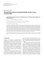
In this paper, we consider the problem of tracking objects
using highly directional sensors, that is, sensors whose field
of vision is a very narrow sector or a line. Sensors that fall into
this class are lasers and highly directional infrared tempera-
ture sensors. Figure 1 compares the possible field of vision of
omnidirectional, directional, and highly directional sensors.
Although the ideas introduced in this paper are applicable to
highly directional sensors, in Section 8 we discuss how they
can be extended to other types of sensors.
Target tracking in sensor networks has received much at-
tention in the literature; see, for example, [1–13]. The use
of information provided by detected objects to improve the
accuracy of sensor localization schemes has also been pro-
posed, although in a different context. In [14], connectivity
information and information provided by objects detected
by omnidirectional sensors are used to determine, for each
sensor, a region in which it is located.
In this paper, we treat the problem of estimating the
trajectory of objects moving in straight lines using highly
2 EURASIP Journal on Advances in Signal Processing
(a) (b)
(c) (d)
Figure 1: Sensor types: omnidirectional (a), directional (b) and (c),
and highly directional (d).
directional sensors. A network of highly directional sensors
monitors a region of the plane. The location of the sensors
and the directions of their fields of vision are unknown a pri-
ori. Sporadically, objects moving in straight lines and con-
stant speed cross the region. We assume that only one object
is in the region at any given time. We are not concerned with
identity management.
A sensor detects an object when it crosses its field of vi-
sion. Sensors cannot measure distance or angle. The only in-
formation available to the sensors are the detection times.
The estimation of the trajectories and the sensor lines must
be done from this time information only. This estimation
problem involves the minimization of a highly nonconvex
cost function, as is often the case in many such inference
problems.
To find the global minimum of such cost function we in-
troduce an algorithm, which we call an “adaptive basis algo-
rithm.” This algorithm is divided into three phases. In the
first phase, the algorithm is initialized using the detection
times of four objects and six sensors. The algorithm estimates
the directions and speeds of the four objects, and the sens-
ing lines of the six sensors in an “ad Hoc” coordinate sys-
tem, which we call “adaptive coordinate system.” The rea-
son for this name will become clear in the sequel. In the
second phase, the estimates are updated, as new data is col-
lected from new sensors or objects. The third phase is an op-
tional coordinate transformation, to obtain the estimates in
the real-world coordinate system.
In the next section, we give an overview of the problem
we study, and in Section 3 we give the formal setup. Section 4
contains the main ideas behind the adaptive basis algorithm,
while Section 5 describes the algorithm in detail. We provide
the results of simulations in Section 6, and an implementa-
tion in Section 7. Finally Section 8 contains conclusions and
comments.
2. OVERVIEW OF TRAJECTORY ESTIMATION
PROBLEM USING DIRECTIONAL SENSORS
A certain region is monitored by a network of directional
sensors whose positions and orientations themselves are ini-
tially unknown. The region is crossed sporadically by objects
assumed to be moving at constant velocity, at least within a
bounded domain of interest. We assume that only one object
is in the region at a time. There is no need to keep track of
the identity of the objects. The task of the network is to detect
each object and determine its motion trajectory.
The algorithm developed in this paper uses minimal in-
formation, namely, only the detection times of the objects.
No distance or angle measurements are needed. We will con-
sider the extreme situation where nothing is known a priori:
even the locations of the sensors and the directions at which
the sensors point are unknown a priori. The sensor directions
are also to be estimated as part of the problem. The central is-
sue is how to estimate both trajectories and sensor lines from
time measurements only.
We model objects as points, and the “line of sight” of
each sensor simply as a straightline. A sensor detects an ob-
ject when it crosses its line of sight. Thus the data and input
to the algorithm are the object detection times. Such a sys-
tem requires a clock synchronization algorithm, and in our
system the algorithm developed in [15]wasused.
A detailed description of the setup for this application is
given in Section 3.
In Section 7, we show an implementation of this scenario
using lasers. Lasers are pointed at motes equipped with light
sensors which detect the presence of a passing vehicle. Detec-
tion times are used to estimate the speed and direction of the
car, as well as the straightlines formed by the laser beams.
The estimation of the trajectories as well as the sensor
lines involves the minimization of a nonconvex cost function.
This cost function presents a large number of local minima.
We need to find the global minimum of this cost in order to
accurately estimate the parameters. In Section 5,wepresent
an algorithm to do so.
Equation (6) in the sequel, which shows the cost for just
three objects and two sensors, clearly illustrates the difficulty
of this problem. We are, however, able to exploit the specific
structure of this problem to solve it. The algorithm can be
divided into three phases.
(1) In phase 1, an initial solution is found using the de-
tection times of the first four objects and six sensors
(see Section 4). It is surprising that this problem can
be solved in closed form. For this, we first need to find
an adequate coordinate system in which to express the
geometric relationships of the objects and sensors. We
call this an “adaptive basis.” The key to our solution is
that when expressed in the adaptive basis, this initial
problem can be solved in closed form. Any other fixed
coordinate system does not have such a property.
(2) In phase 2, as new objects arrive, the parameters of the
new objects are estimated, and all other earlier param-
eters are updated. Similarly, if more than six sensors
are available, their observed crossing times can be in-
corporated progressively into the algorithm.
(3) Phase 3 is optional, and involves a coordinate trans-
formation to obtain the parameter estimates in the
real-world coordinate system. For this, additional in-
formation, such as the location of six sensors or the
trajectories of two objects in the desired real-world co-
ordinate system is needed.
Kurt Plarre and P. R. Kumar 3
In the next section, we give the formal setup of the problem.
3. PROBLEM SETUP
Let us suppose that the equation of the line of sight of sensor
s
i
is
x
s
i
a
s
i
+
y
s
i
b
s
i
= 1ora
s
i
x
s
i
+ b
s
i
y
s
i
= 1,
(1)
where a
s
i
and b
s
i
are the intercepts of the sensing line of s
i
with the horizontal and vertical axis, respectively. Also sup-
pose that the motion of object o
j
is described by the follow-
ing equations, where t denotes time:
x
o
j
(t) = v
x
o
j
t + x
0
o
j
,
y
o
j
(t) = v
y
o
j
t + y
0
o
j
.
(2)
Here, v
x
o
j
and v
y
o
j
are the horizontal and vertical speeds of o
j
,
respectively, and (x
0
o
j
, y
0
o
j
) is the location of o
j
at time zero.
The parameters (a
s
i
, b
s
i
) for the sensors s
i
, and the pa-
rameters (v
x
o
j
, x
0
o
j
, v
y
o
j
, y
0
o
j
) for the various objects o
j
are all
unknown a priori, and it is desired to estimate them.
The time at which sensor s
i
detects object o
j
is then
t
o
j
s
i
=
1 − a
s
i
x
0
o
j
−b
s
i
y
0
o
j
a
s
i
v
x
o
j
+ b
s
i
v
y
o
j
+ ν
o
j
s
i
,(3)
where we assume that ν
o
j
s
i
is zero-mean noise, and ν
o
j
s
i
is inde-
pendent of ν
o
j
s
k
for (s
i
,o
j
)=(s
k
,o
l
).
Corresponding to t
o
j
s
i
associate the “equation error,”
τ
o
j
s
i
:=
a
s
i
v
x
o
j
+ b
s
i
v
y
o
j
t
o
j
s
i
+
a
s
i
x
0
o
j
+ b
s
i
y
0
o
j
−
1. (4)
The estimation of the object motion and sensor direction pa-
rameters will be based on the minimization of the cost func-
tion that is the sum of the squares of the errors:
J
=
i,j
τ
o
j
s
i
2
,(5)
over the parameters (a, b) of the sensors and (v
x
, x
0
, v
y
, y
0
).
For simplicity, the arguments of J, which are all the unknown
parameters, are not shown explicitly.
To see the difficulty of minimizing (5), we detail the ex-
panded form of J, for just three sensors and two objects:
J
=
a
s
1
v
x
o
1
+ b
s
1
v
y
o
1
t
o
1
s
1
+
a
s
1
x
0
o
1
+ b
s
1
y
0
o
1
−1
2
+
a
s
1
v
x
o
2
+ b
s
1
v
y
o
2
t
o
2
s
1
+
a
s
1
x
0
o
2
+ b
s
1
y
0
o
2
−1
2
+
a
s
2
v
x
o
1
+ b
s
2
v
y
o
1
t
o
1
s
2
+
a
s
2
x
0
o
1
+ b
s
2
y
0
o
1
−
1
2
+
a
s
2
v
x
o
2
+ b
s
2
v
y
o
2
t
o
2
s
2
+
a
s
2
x
0
o
2
+ b
s
2
y
0
o
2
−1
2
+
a
s
3
v
x
o
1
+ b
s
3
v
y
o
1
t
o
1
s
3
+
a
s
3
x
0
o
1
+ b
s
3
y
0
o
1
−
1
2
+
a
s
3
v
x
o
2
+ b
s
3
v
y
o
2
t
o
2
s
3
+
a
s
3
x
0
o
2
+ b
s
3
y
0
o
2
−1
2
.
(6)
Note that (5) is a nonconvex function of
a
s
i
, b
s
i
, v
x
o
j
, x
0
o
j
, v
y
o
j
, y
0
o
j
;1<i<3, 1 <j<2
,(7)
the sensor and object parameters. Note also that even for just
four objects and six sensors, the number of unknown param-
eters is 4
× 4+6× 2 = 28. Only the global minimum is an
acceptable solution, not local minima, and only an exhaus-
tive search could ensure that one finds it; but such a search
would be too computationally expensive.
We will develop a recursive algorithm by which the data
provided by four objects and six sensors is used to determine
an initial solution. The data provided by other sensors and
objects is subsequently recursively incorporated into the al-
gorithm, thus improving the accuracy of the solution.
To determine the minimum of (5), we devise a novel
two-phase algorithm, with an optional third phase that cor-
responds to the final coordinate transformation.
It is important to mention that there are certain “degen-
erate” cases that cannot be handled by the algorithm. For ex-
ample, if the first two objects travel in the same direction, or
all sensors lines are parallel. We assume that such cases will
not happen in practice (or have a small probability of hap-
pening), and do not consider them.
4. THE MAIN IDEAS
The central issue is how to circumvent the problem of find-
ing the global minimum of the nonconvex cost function (5).
Ourkeyideatoovercomethisistochooseanadaptiveba-
sis, which can be optionally transformed at a later phase. We
note that since we do not know the real-world coordinate sys-
tem, we must choose a “custom” system in which to state the
equations and thus localize the sensor rotations and the mo-
tions of the objects. Later on, we will use the locations of six
sensors, if known, to transform the so-obtained parameters
to the correct representation. This can be done at any point
of the algorithm.
Since we are free to choose our coordinate system, we will
choose it in such a way that it simplifies the expressions. In
fact, if the coordinate system is not carefully chosen, the re-
sulting equations cannot be solved in closed form. We thus
have the task of finding the right coordinate system in which
to write the equations, and then finding a procedure to solve
them.
We choose the adaptive coordinate system in the follow-
ing way.
(1) The motion of the first object is used to fix the “hor-
izontal” axis, with its position at time t
= 0defined
as the origin, and speed normalized to 1. As will be
shown in Section 5, this fixes all parameters of o
1
in
the custom system.
(2) The motion of the second object is used to fix the “ver-
tical” axis, with its speed also normalized to 1. How-
ever, since its position at time t
= 0 is unknown, two
parameters corresponding to o
2
, its two coordinates
at time t
= 0, will be undetermined (as detailed in
Section 5).
4 EURASIP Journal on Advances in Signal Processing
t = 0
o
2
t = 0
o
1
(0, 0)
(
x
0
o
2
, y
0
o
2
)
Figure 2: Adaptive coordinate system obtained from the trajecto-
ries of the first two objects.
We then divide the process into two-phases. In the first phase,
we use the data obtained from only m sensors and n objects,
where m and n are chosen in such a way that (5) can be set
exactly to zero, independent of the noise. Solving the result-
ing equation provides an initial estimate of the parameters.
In the second phase, as new data are incorporated into the
problem, the sensor and object parameter estimates are re-
fined, using a local improvement algorithm.
To determine the number of sensors and object measure-
ments needed to determine the initial estimates, that is, n and
m, we reason in the following way.
(1) Each remaining object o
j
used in the first phase will
add four unknown parameters to the problem: v
x
o
j
, x
0
o
j
,
v
y
o
j
,andy
0
o
j
.
(2) Each sensor s
i
included in this phase will add two un-
known parameters to define its “line.”
(3) On the other hand, the number of data measurements
obtained from the detection of the first n objects by m
sensors is nm.
Considering that we need at least the same number of data
variables as the number of unknown parameters to solve the
equations, we need
nm
≥ 4(n −2)+2+2m,(8)
which is satisfied by m
= 6, and n = 3. We thus need at least
six sensors and three objects to initialize the system. How-
ever, we will see in Section 5.1 that the resulting equation is
quadratic,andwewillneedthedatafromafourthobjectto
resolve the sign of the root.
5. THE ALGORITHM
In this section, we present the estimation algorithm.
5.1. First phase
During the first phase, after deployment, all sensors are
awake, waiting for the first four objects. The data collected
from these objects is used to form an initial estimate of the
object and sensor parameters. As mentioned before, the first
object is used to fix the “horizontal” axis of the adaptive coor-
dinate system (see Figure 2). The point on the plane at which
o
1
was at time t = 0 represents the origin of the coordinate
system. The direction of motion determines the axis, and the
scale is given by assuming that the speed of o
1
is 1.
The second object fixes the vertical axis (see Figure 2).
The direction of motion of o
2
determines the axis, while the
scale is given by assuming that its speed is 1. The point at
which o
2
is at time t = 0 is unknown. We call this point
(
x
0
o
2
, y
0
o
2
). These two parameters x
0
o
2
and y
0
o
2
are unknown
even with respect to the adaptive basis and must be estimated
as part of the problem.
In our coordinate system, we know that the line corre-
sponding to sensor s
i
passes through the points (t
o
1
s
i
,0) and
(
x
0
o
2
, y
0
o
2
+ t
o
2
s
i
). Thus, the equation for s
i
inthissystemisde-
termined as
y
s
i
x
s
i
−t
o
1
s
i
=
y
0
o
2
+ t
o
2
s
i
x
0
o
2
−t
o
1
s
i
. (9)
Hence, subject only to (
x
0
o
2
, y
0
o
2
) being unknown, each sen-
sor’s line is determined.
Now we turn to the second object. Reordering (9), we
obtain
x
0
o
2
−t
o
1
s
i
y
s
i
=
y
0
o
2
+ t
o
2
s
i
x
s
i
−t
o
2
s
i
y
0
o
2
−t
o
1
s
i
t
o
2
s
i
. (10)
Consider now the third object o
3
. Assume that the equation
for o
3
in our coordinate system is
x
o
3
(t) = v
x
o
3
t + x
0
o
3
, y
o
3
(t) = v
y
o
3
t + y
0
o
3
.
(11)
We know o
3
is detected by sensor s
i
at time t
o
3
s
i
. Combining
this information with (10), we obtain
x
0
o
2
−t
o
1
s
i
y
0
o
3
+ v
y
o
3
t
o
3
s
i
=
y
0
o
2
+ t
o
2
s
i
x
0
o
3
+ v
x
o
3
t
o
3
s
i
−t
o
1
s
i
y
0
o
2
−t
o
1
s
i
t
o
2
s
i
.
(12)
Let M be a matrix such that its ith row is
[M]
i,∗
:=
x
0
o
2
−t
o
1
s
i
, t
o
3
s
i
x
0
o
2
−t
o
2
s
i
, −
y
0
o
2
+ t
o
2
s
i
,
−t
o
3
s
i
y
0
o
2
+ t
o
2
s
i
,
t
o
1
s
i
y
0
o
2
+ t
o
1
s
i
t
o
2
s
i
.
(13)
Likewise, let v :
= [y
0
o
3
, v
y
o
3
, x
0
o
3
, v
x
o
3
,1]
T
. Then, from (12), we
can write the linear system as Mv
= 0. If M was not column-
rank deficient, then the unique solution to this system would
be v
= (M
T
M)
−1
0 = 0. However, since this system has a non-
trivial solution, M is column-rank deficient. Let us rewrite M
in term of its columns. For this, let us first define the follow-
ing:
e := [1, 1, ,1]
T
,
T
o
1
:=
t
o
1
s
1
, t
o
1
s
2
, , t
o
1
s
m
T
,
T
o
2
:=
t
o
2
s
1
, t
o
2
s
2
, , t
o
2
s
m
T
,
T
o
3
:=
t
o
3
s
1
, t
o
3
s
2
, , t
o
3
s
m
T
,
T
o
2
o
1
:=
t
o
1
s
1
t
o
2
s
1
, t
o
1
s
2
t
o
2
s
2
, , t
o
1
s
m
t
o
2
s
m
T
,
T
o
3
o
1
:=
t
o
1
s
1
t
o
3
s
1
, t
o
1
s
2
t
o
3
s
2
, , t
o
1
s
m
t
o
3
s
m
T
,
T
o
3
o
2
:=
t
o
2
s
1
t
o
3
s
1
, t
o
2
s
2
t
o
3
s
2
, , t
o
2
s
m
t
o
3
s
m
T
.
(14)
Kurt Plarre and P. R. Kumar 5
With these definitions we can write M as
M
=
x
0
o
2
e− T
o
1
, x
0
o
2
T
o
3
−T
o
3
o
1
, −y
0
o
2
e− T
o
2
,
− y
0
o
2
T
o
3
−T
o
3
o
2
, y
0
o
2
T
o
1
+T
o
2
o
1
.
(15)
Since M is column-rank deficient, there exist real numbers
α
1
, α
2
, α
3
, α
4
, α
5
, such that
α
1
x
0
o
2
e −T
o
1
+ α
2
x
0
o
2
T
o
3
−T
o
3
o
1
+ α
3
−
y
0
o
2
e −T
o
2
+α
4
−
y
0
o
2
T
o
3
−T
o
3
o
2
+ α
5
y
0
o
2
T
o
1
+T
o
2
o
1
=
0.
(16)
Collecting terms, and defining
M :=
e, T
o
1
, T
o
3
, T
o
2
, T
o
3
o
1
, T
o
3
o
2
, T
o
2
o
1
,
v :=
α
1
x
0
o
2
−α
3
y
0
o
2
, α
5
y
0
o
2
−α
1
, α
2
x
0
o
2
−α
4
y
0
o
2
,
−α
3
, −α
2
, −α
2
, −α
4
, α
5
T
,
(17)
we can rewrite (16)as
Mv = 0. (18)
Let [θ
1
, θ
2
, θ
3
, θ
4
, θ
5
, θ
6
]
T
be the solution to (18), with α
5
=
1. Then
α
1
x
0
o
2
−α
3
y
0
o
2
= θ
1
,
α
5
y
0
o
2
−α
1
= θ
2
,
α
2
x
0
o
2
−α
4
y
0
o
2
= θ
3
,
−α
3
= θ
4
,
−α
2
= θ
5
,
−α
4
= θ
6
,
α
5
= 1.
(19)
Solving this nonlinear system, one obtains
x
0
o
2
=
α
5
θ
3
+ α
4
θ
2
+ α
2
α
3
2α
2
α
5
±
α
5
θ
3
+ α
4
θ
2
+ α
2
α
3
2
+4α
2
α
5
α
4
θ
1
−α
3
θ
3
2α
2
α
5
.
(20)
To resolve the sign in (20) we make use of the data provided
by the fourth object o
4
. We simply choose the sign that con-
forms to the detection times t
o
4
s
i
.
Once the value of
x
0
o
2
is known, the rest of the parameters
can be easily computed.
5.2. Second phase
Once the parameters for the first four objects and six sensors
have been estimated, most sensors go to sleep. A few sentinel
sensors stay awake and sensing. When a sentinel sensor de-
tects an object, it wakes up the complete sensor network. All
sensors then wait for the object and register the time at which
they detect it. It is important to note that some sensors will
not detect a given object, since they may wake up too late.
This is illustrated in Figure 3.
o
j
s
k
Wake u p
s
i
(a)
o
j
s
k
s
i
(b)
Figure 3: Some objects are not detected by all sensors: (a) s
k
wakes
up too late to detect o
j
,(b)s
i
only covers a half-line, while s
k
has a
limited range.
o
6
o
5
o
4
o
3
o
2
o
1
s
1
s
2
s
3
s
4
s
5
s
6
s
7
s
8
s
9
11111 11
111111 1
11111 11
111111
11111
11 1
Figure 4: Example of a matrix Ω
s
i
indicating the measurements
known to s
i
.
Each sensor has at most one detection time for the new
object. To form an estimate of the trajectory of this object, at
least four measurements are necessary. To gather this infor-
mation, sensors share their measurements (if they have any),
and collect measurements from other nodes. The obtained
data are used to refine the estimates of all parameters.
To organize the computations, for each node s
i
,wedefine
amatrixΩ
s
i
, such that
Ω
s
i
k,l
:=
⎧
⎨
⎩
1ifs
i
knows t
o
l
s
k
,
0 otherwise.
(21)
An example matrix Ω
s
i
is shown in Figure 4.
For each s
k
,andobjecto
l
,letO
s
i
s
k
and S
s
i
o
l
be defined as
O
s
i
s
k
:={l | Ω
s
i
k,l
= 1}, S
s
i
o
l
:={k | Ω
s
i
k,l
= 1}.
(22)
The cost corresponding to sensor s
i
is then given by
J
s
i
=
k
l∈O
s
i
s
k
a
s
i
s
k
v
x,s
i
o
l
t
o
l
s
k
+ a
s
i
s
k
x
0,s
i
o
l
+ b
s
i
s
k
v
y,s
i
o
l
t
o
l
s
k
+ b
s
i
s
k
y
0,s
i
o
l
−1
2
,
(23)
where
a
s
i
s
k
, b
s
i
s
k
, v
x,s
i
o
l
, x
0,s
i
o
l
, v
y,s
i
o
l
,andy
0,s
i
o
l
are the estimated pa-
rameters at s
i
. We use a block coordinate descent method (see
[16]) to minimize J
s
i
.Sensors
i
performs one phase of New-
ton’s algorithm for each row and column of Ω
s
i
sforwhich
there is enough data. This is done cyclically.
6 EURASIP Journal on Advances in Signal Processing
Letusfirstdefine
A
s
i
s
k
,o
l
:= v
x,s
i
o
l
t
o
l
s
k
+ x
0,s
i
o
l
,
B
s
i
s
k
,o
l
:= v
y,s
i
o
l
t
o
l
s
k
+ y
0,s
i
o
l
,
C
s
i
o
k
,o
l
:= a
s
i
s
k
,
D
s
i
o
k
,o
l
:= a
s
i
s
k
t
o
l
s
k
,
E
s
i
o
k
,o
l
:= b
s
i
s
k
,
F
s
i
o
k
,o
l
:= b
s
i
s
k
t
o
l
s
k
,
J
s
i
=
k
l∈O
s
i
s
k
A
s
i
s
k
,o
l
a
s
i
s
k
+ B
s
i
s
k
,o
l
b
s
i
s
k
−1
2
=
l
k∈S
s
i
o
l
D
s
i
o
k
,o
l
v
x,s
i
o
l
+ C
s
i
o
k
,o
l
x
0,s
i
o
l
+ F
s
i
o
k
,o
l
v
y,s
i
o
l
+ E
s
i
o
k
,o
l
y
0,s
i
o
l
−1
2
.
(24)
To simplify the expressions, let us also define v
s
i
s
k
:= [a
s
i
s
k
,
b
s
i
s
k
]
T
,
g
s
i
s
k
:=
⎡
⎢
⎢
⎢
⎣
l∈O
s
i
s
k
A
s
i
s
k
,o
l
a
s
i
s
k
+ B
s
i
s
k
,o
l
b
s
i
s
k
−1
A
s
i
s
k
,o
l
l∈O
s
i
s
k
A
s
i
s
k
,o
l
a
s
i
s
k
+ B
s
i
s
k
,o
l
b
s
i
s
k
−1
B
s
i
s
k
,o
l
⎤
⎥
⎥
⎥
⎦
,
H
s
i
s
k
:=
⎡
⎢
⎢
⎢
⎢
⎣
l∈O
s
i
s
k
A
s
i
s
k
,o
l
2
l∈O
s
i
s
k
A
s
i
s
k
,o
l
B
s
i
s
k
,o
l
l∈O
s
i
s
k
B
s
i
s
k
,o
l
A
s
i
s
k
,o
l
l∈O
s
i
s
k
B
s
i
s
k
,o
l
2
⎤
⎥
⎥
⎥
⎥
⎦
.
(25)
Applying Newton’s method to (23)withrespectto
a
s
k
and b
s
k
,
we obtain the recursion
v
s
i
s
k
v
s
i
s
k
−(H
s
i
s
k
)
−1
g
s
i
s
k
. (26)
Similar expressions are obtained by Newton’s method ap-
plied to (23), with respect to v
x,s
i
o
l
, x
0,s
i
o
l
, v
y,s
i
o
l
,andy
0,s
i
o
l
.
5.3. Third phase: coordinate transformation
Once the parameters of the sensors and objects have been es-
timated in the adaptive coordinate system, they can be trans-
formed into the real-world system if the locations of six sen-
sors are known. The linear coordinate transformation can be
represented as
x
adaptive
y
adaptive
=
A
1,1
A
1,2
A
2,1
A
2,2
x
real
y
real
+
d
x
d
y
. (27)
Let us assume, without loss of generality, that we know the
locations of sensors s
1
to s
6
. In the adaptive system, each sen-
sor satisfies the equation corresponding to its line of sight.
We c an t hus w r ite
x
adaptive
s
i
a
s
i
+
y
adaptive
s
i
b
s
i
= 1 (28)
for i
= 1, 2, ,6,or
A
1,1
x
real
s
i
+ a
1,2
y
real
s
i
+ d
x
a
s
i
+
A
2,1
x
real
s
i
+ A
2,2
y
real
s
i
+ d
y
b
s
i
= 1.
(29)
1
0
01
Object direction
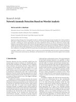
Figure 5: Setup for simulations. Sensors are shown as circles along
the bottom of the figure; their directions are shown by lines. The
dark parallel horizontal lines indicate the boundaries of the region
of interest.
This 6 × 6 system of equations can be solved for A
1,1
, A
1,2
,
A
2,1
, A
2,2
, d
x
,andd
y
. Once the transformation is known, we
can use (29) to recover the lines of sight of the sensors in the
real-world system. Grouping terms in (29)weobtain
a
real
=
1 − d
x
/a − d
y
/
b
A
1,1
/a + A
2,1
/
b
, b
real
=
1 − d
x
/a − d
y
/
b
A
2,1
/a + A
2,1
/
b
.
(30)
6. A SIMULATION STUDY
We first present the results of a preliminary simulation study
that was conducted prior to an actual implementation, which
we shall describe in the sequel.
Figure 5 shows the setup for the simulations. A section of
a passage (e.g., a road, bridge, tunnel, etc.) is monitored by
a collection of m sensors located along the sides of the pas-
sage. The length of the section is L, and its width is W.In
the simulations, L
= W = 1. Sensors located on the left side
of the section are pointed to the right, while those located
at the right side are pointed to the left. Sensors are located
regularly, except for noise in their positions, and the angles
of their lines of sight are approximately 63
o
. Notice that, al-
though in the simulations in this section and the implemen-
tation presented in Section 7 the sensors are placed regularly,
the actual location of each sensor is irrelevant to the perfor-
mance of the algorithm. It is the direction of the sensor lines,
not the location of the sensors on those lines, what deter-
mines the behavior of the algorithm.
Theexactanglesofthesensorsmustberecoveredfrom
the measurements, as part of the problem. We have purposely
avoided situations in which sensors are “close to vertical” or
“close to horizontal,” since such situations produce numer-
ical problems. The measurement errors are uniformly dis-
tributed in [
−0.01, 0.01]. Objects enter the section from the
left and exit it from the right. The speed of the objects is
chosen uniformly and independently in the range [0.01, 0.1],
Kurt Plarre and P. R. Kumar 7
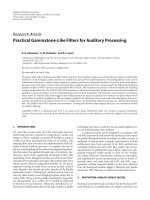
Average Jp
0.06
0.05
0.04
0.03
0.02
0.01
0
0 102030405060708090100
Object number
Figure 6: Average estimation error (J
p
), as a function of the number
of detected objects, for 100 different runs of the algorithm.
while their trajectories are fixed by choosing random entry
and exit points. To ensure that the two first trajectories are
not parallel, they are fixed: the first trajectory entering and
exiting at the bottom, and the second trajectory entering at
the bottom and exiting at the top (thus maximizing the angle
between them).
The estimation of the sensor and object parameters is
done by minimizing the quadratic cost function (5), al-
though the quality of the resulting estimates is assessed by
the cost defined by
2m +4n
J
p
:=
m
i=1
a
s
i
−a
s
i
2
+
b
s
i
−b
s
i
2
+
n
j=1
v
x
o
j
−v
x
o
j
2
+
x
0
o
j
−x
0
o
j
2
+
v
y
o
j
−v
y
o
j
2
+
y
0
o
j
−y
0
o
j
2
,
(31)
where
m,andn are the number of sensors and objects, re-
spectively. The behavior of J
p
for the first 100 objects (af-
ter the passage of the initial four objects necessary to initial-
ize the algorithm) for 100 different runs of the algorithm is
shown in Figure 6. The curve shown corresponds to an aver-
age over the 100 runs of the simulation.
It is clear from Figure 6 that the quality of the estima-
tion improves with the number of detected objects, which is
as desired. It is important to mention the importance of the
refining phase, phase 2, to improve the performance of the
algorithm when measurements are noisy.
To illustrate the importance of the first phase of the al-
gorithm, we compare in Figure 7 the error in the parameter
estimates J
p
for the first six sensors and four objects, given by
the adaptive basis algorithm (crosses), versus that of a ran-
domly restarted local improvement algorithm (dots). In each
simulation, the local improvement algorithm was restarted at
100 different points, and the best parameter estimates chosen
Jp
100
90
80
70
60
50
40
30
20
10
0
0 102030405060708090100
Simulation number
Figure 7: Error in parameter estimates given by the adaptive basis
algorithm (crosses), and a randomly restarted local improvement
algorithm (dots).
as the ones minimizing (5). The random initialization points
were obtained in the same fashion as the actual parameters
of sensors and objects. No noise in the data was considered.
ItcanbeseeninFigure 7 that the local improvement algo-
rithm is unable to find the optimum parameter estimates, in
contrast to the adaptive basis algorithm. This is due to the
non-convexity of the cost function (5), that is, the local im-
provement algorithm is able to find only local minima of the
cost function. The adaptive basis algorithm finds the global
minimum.
7. IMPLEMENTATION
The system described in the previous sections was imple-
mented using Berkeley mica2 motes provided with light sen-
sors. The directional sensors were implemented using laser
pointers, pointed directly at the light sensors. A toy car was
used to simulate the objects.
7.1. Setup for the experiments
The setup for the experiments is shown in Figure 8. Six light
sensors and six lasers were placed on different sides of a track
of length 16 foot and width 8 foot. The speed of the car was
approximately constant equal to 1.41 ft/s.
A picture of the testbed is shown in Figure 9. The car is
the object positioned between the sensors and the lasers.
As the car runs through the laser field, it interrupts the
lasers. The motes detect the interruption times. The times are
transmitted to a seventh mote, which runs the algorithm. Af-
ter the car has passed four times, the seventh mote estimates
the entry and exit points of the fourth car. Then, for each
subsequent pass, the estimated parameters are updated, and
the entry and exit points of the current pass are estimated.
To perform the coordinate transformation, the trajecto-
ries of the two first objects were fixed. The first object entered
at 0 and exited at 0, while the second object entered at 0 and
8 EURASIP Journal on Advances in Signal Processing
8
6
4
2
0
0 2 4 6 8 10 12 14 16
Figure 8: Setup for experiments. Sensors are shown as the black
disks at the bottom of the figure. Lasers are represented by disks at
the top of the figure.
Figure 9: Picture of the testbed. Sensors can be seen on the left,
lasers on the right. The car that was used as an “object” can be seen
in the middle.
exited at 8. This was done because the locations of the sensors
were hard to measure. This also improved the estimation ac-
curacy, because it maximized the angle between the first two
sensors.
Let v denote the speed of the car. The coordinate trans-
formation can be obtained, from the following:
(1) Point (1, 0) in the adaptive basis corresponds to point
(v,0) in the real-world.
(2) Point (0, 1) in the adaptive basis corresponds to
(v(16/
√
16
2
+8
2
), v(8/
√
16
2
+8
2
)) in the realworld.
Theconversionisfoundfrom
A
10
01
=
1.41 1.26
00.63
. (32)
We then have that
a
real
=
1
[A]
1,1
/a +[A]
2,1
/
b
,
b
real
=
1
[A]
1,2
/a +[A]
2,2
/
b
.
(33)
7.2. Results
We discuss here the results of the experiments. We focus on
one experiment with 32 runs, although we performed exper-
iments with up to 40 runs.
Figure 10 shows the actual and estimated entry and exit
points for four runs out of 32 runs. It is important to note
that the algorithm is able to estimate the entry and exit points
with good accuracy, and that it remains stable, even after a
large number of objects have passed. The histograms for the
errors in entry and exit points for 4–32 runs are shown in
Figure 11. The maximum number of objects in one single ex-
periment was 40. After each run, all parameters from previ-
ous runs, and all sensor parameters were updated. The num-
ber of iterations of Newton’s method was fixed to 5, rather
than checking for convergence.
Figure 11 shows a histogram of the estimation errors in
entry and exit points. Again, we can see that the algorithm
was able to accurately estimate the trajectories of the objects.
8. CONCLUSIONS
We considered the problem of tracking objects moving in
straightlines, using a network of highly directional sensors.
This estimation problem involves a highly nonconvex opti-
mization problem. To overcome this difficulty we introduced
a three phase algorithm, which we call the adaptive basis al-
gorithm. We simulated the algorithm and have implemented
it in a laboratory setting.
The adaptive basis algorithm assumes that the field of vi-
sion of the sensors are straightlines, but it might be possible
to extend this algorithm to handle omnidirectional sensors
and directional sensors with a field of vision given by a con-
vex sector, rather than a line. We discuss here such possibili-
ties.Thisismatteroffuturework.
Assume that two omnidirectional sensors are located on
a plane, and measure the intensity of a signal produced by an
object. Suppose also that the object is small, and the fields of
vision of the sensors are perfect discs. If the object is located
closer to one sensor than the other, such sensor will measure
a higher intensity. If the two sensors compare their measure-
ments, they can determine the moment at which the object
crosses the bisector line between them. Collecting such cross-
ing times from different objects and sensor pairs would pro-
vide data that could be used to estimate the trajectories of the
objects, and the bisector lines of the sensors.
From Figure 1(b) we notice that although the field of vi-
sion of a directional sensor might be a convex sector rather
than a line, the edges of such sector are lines. Sensors might
record the times at which an object enters or exits their field
of vision. An additional difficulty that must be overcome in
this case is to determine in each case, on which “side” of the
sector the object entered, and on which it exited, and to elim-
inate the data of objects entering through the “front.”
The adaptive basis algorithm uses minimal information.
Nothing is known a priori. If more information is available,
for example, the trajectories of some of the objects or the di-
rections of some of the sensor lines, and so forth, this could
be used to improve the estimates or simplify the estimation.
Kurt Plarre and P. R. Kumar 9
Run 4
8
6
4
2
0
0 2 4 6 8 10 12 14 16
(a)
Run 13
8
6
4
2
0
0 2 4 6 8 10 12 14 16
(b)
Run 22
8
6
4
2
0
0 2 4 6 8 10 12 14 16
(c)
Run 31
8
6
4
2
0
0 2 4 6 8 10 12 14 16
(d)
Figure 10: Runs 4, 13, 22, and 31 from an experiment with a total of 32 runs. Top circles are lasers, bottom dark circles are sensors. Sensor
lines are shown with dotted lines. Note that the sensor lines shown were estimated from the data. The domain is a rectangle marked with a
thick borderline. The actual trajectory is shown as a left-to-right thick line. Estimated entry and exit points are indicated with triangles.
8
6
4
2
0
00.20.40.60.81 1.21.4
(a)
30
20
10
0
−5 −4 −3 −2 −101234
(b)
Figure 11: Histograms for errors in entry and exit points for a 32-
run (objects) experiment.
ACKNOWLEDGMENTS
This material is based upon work partially supported by
NSF under Contracts nos. NSF ANI 02-21357 and CCR-
0325716, USARO under Contracts nos. DAAD19-00-1-
0466 and DAAD19-01010-465, DARPA/AFOSR under Con-
tract no. F49620-02-1-0325, DARPA under Contracts nos.
N00014-0-1-1-0576 and F33615-0-1-C-1905, and AFOSR
under Contract no. F49620-02-1-0217.
REFERENCES
[1] A. Arora, P. Dutta, S. Bapat, et al., “A line in the sand: a wireless
sensor network for target detection, classification, and track-
ing,” Computer Networks, vol. 46, no. 5, pp. 605–634, 2004.
[2] C. Gui and P. Mohapatra, “Power conservation and quality of
surveillance in target tracking sensor networks,” in Pro ceedings
of the 10th Annual International Conference on Mobile Com-
puting and Networking (MobiCom ’04), pp. 129–143, Philadel-
phia, Pa, USA, September-October 2004.
10 EURASIP Journal on Advances in Signal Processing
[3] W P. Chen, J. Hou, and L. Sha, “Dynamic clustering for acous-
tic target tracking in wireless sensor networks,” IEEE Transac-
tions on Mobile Computing, vol. 3, no. 3, pp. 258–271, 2004.
[4] T. Vercauteren, D. Guo, and X. Wang, “Joint multiple target
tracking and classification in collaborative sensor networks,”
IEEE Journal on Selected Areas in Communications, vol. 23,
no. 4, pp. 714–723, 2005.
[5] Y. He and K. P. Chong, “Sensor scheduling for target tracking
in sensor networks,” in Proceedings of the 43th IEEE Confer-
ence on Decision and Control (CDC ’04), vol. 1, pp. 743–748,
Atlantis, Bahamas, December 2004.
[6] J. E. Bevington, “Distributed sensor management and tar-
get tracking for unattended ground sensor networks,” in Bat-
tlespace Digitization and Network-Centric Systems IV, vol. 5441
of Proceedings of SPIE, pp. 25–35, Orlando, Fla, USA, April
2004.
[7] R. R. Brooks, P. Ramanathan, and A. Sayeed, “Distributed tar-
get classification and tracking in sensor networks,” Proceedings
of the IEEE, vol. 91, no. 8, pp. 1163–1171, 2003.
[8] J.Liu,M.Chu,J.Liu,J.Reich,andF.Zhao,“Distributedstate
representation for tracking problems in sensor networks,” in
Proceedings of the 3rd International Symposium on Information
Processing in Sensor Networks (IPSN ’04), pp. 234–242, Berke-
ley, Calif, USA, April 2004.
[9] J. Liu, P. Cheung, L. Guibas, and F. Zhao, “A dual-space ap-
proach to tracking and sensor management in wireless sensor
networks,” in Proceedings of the 1st ACM International Work-
shop on Wireless Sensor Networks and Applications (WSNA ’02),
pp. 131–139, Atlanta, Ga, USA, September 2002.
[10] M.Horton,A.Broad,M.Grimmer,etal.,“Deploymentready
multimode micropower wireless sensor networks for intrusion
detection, classification, and tracking,” in Unattended Ground
Sensor Technologies and Applications IV, vol. 4743 of Proceed-
ings of SPIE, pp. 307–312, Orlando, Fla, USA, April 2002.
[11] J. Liu, J. Reich, and F. Zhao, “Collaborative in-network pro-
cessing for target tracking,” EURASIP Journal on Applied Sig-
nal Processing, vol. 2003, no. 4, pp. 378–391, 2003.
[12] F. Zhao, J. Shin, and J. Reich, “Information-driven dy-
namic sensor collaboration,” IEEE Signal Processing Magazine,
vol. 19, no. 2, pp. 61–72, 2002.
[13] J. Liu, J. Reich, P. Cheung, and F. Zhao, “Distributed group
management for track initiation and maintenance in target lo-
calization applications,” in Proceedings of the 2nd International
Workshop on Information Processing in Sensor Networks (IPSN
’03), vol. 2634 of Lecture Notes in Computer Science, pp. 113–
128, Palo Alto, Calif, USA, April 2003.
[14] A. Galstyan, B. Krishnamachari, K. Lerman, and S. Pattem,
“Distributed online localization in sensor-networks using a
moving target,” in Proceedings of the 3rd International Confer-
ence on Information Processing in Sensor Networks (IPSN ’04),
pp. 61–70, Berkeley, Calif, USA, April 2004.
[15] R. Solis, V. S. Borkar, and P. R. Kumar, “A new distributed time
synchronization protocol for multihop wireless networks,” in
Proceedings of the 45th IEEE Conference on D ecision and Con-
trol (CDC ’06), pp. 2734–2739, Morgan Kaufmann, San Diego,
Calif, USA, December 2006.
[16] D. P. Bertsekas, Nonlinear Programming, Athena Scientific,
Belmont, Mass, USA, 1995.