Báo cáo hóa học: "A Real-Time Wavelet-Domain Video Denoising Implementation in FPGA" potx
Bạn đang xem bản rút gọn của tài liệu. Xem và tải ngay bản đầy đủ của tài liệu tại đây (1.13 MB, 12 trang )
Hindawi Publishing Corporation
EURASIP Journal on Embedded Systems
Volume 2006, Article ID 16035, Pages 1–12
DOI 10.1155/ES/2006/16035
A Real-Time Wavelet-Domain Video Denoising
Implementation in FPGA
Mihajlo Katona,
1
Aleksandra Pi
ˇ
zurica,
2
Nikola Tesli
´
c,
1
Vladimir Kova
ˇ
cevi
´
c,
1
and Wilfried Philips
2
1
Chair for Computer Eng i neering, University of Novi Sad, Fru
ˇ
skogorska 11, 21000 Novi Sad, Serbia and Montenegro
2
Department of Telecommunications and Information Processing, Ghent University, Sint-Pietersnieuwstraat 41, 9000 Ghent, Belgium
Received 15 December 2005; Accepted 13 April 2006
The use of field-programmable gate arr ays (FPGAs) for digital signal processing (DSP) has increased with the introduction of
dedicated multipliers, which allow the implementation of complex algorithms. This architecture is especially effective for data-
intensive applications with extremes in data throughput. Recent studies prove that the FPGAs offer better solutions for real-time
multiresolution video processing than any available processor, DSP or general-purpose. FPGA design of critically sampled discrete
wavelet transforms has been thoroughly studied in literature over recent years. Much less research was done towards FPGA design
of overcomplete wavelet transforms and advanced wavelet-domain video processing algorithms. This paper describes the paral-
lel implementation of an advanced wavelet-domain noise filtering algorithm, which uses a nondecimated wavelet transform and
spatially adaptive Bayesian wavelet shrinkage. The implemented arithmetic is decentralized and distributed over two FPGAs. The
standard composite telev ision video stream is digitalized and used as a source for real-time video sequences. The results demon-
strate the effectiveness of the developed scheme for real-time video processing.
Copyright © 2006 Mihajlo Katona et al. This is an open access article distributed under the Creative Commons Attribution
License, which permits unrestricted use, distribution, and reproduction in any medium, provided the original work is properly
cited.
1. INTRODUCTION
Video denoising is important in numerous applications, such
as television broadcasting systems, teleconferencing, video
surveillance, and restoration of old movies. Usually, noise re-
duction can significantly improve visual quality of a video as
well as the effectiveness of subsequent processing tasks, like
video coding.
Noise filters that aim at a high visual quality make use of
both spatial and temporal redundancy of video. Such filters
are known as spatio-temporal or three-dimensional (3D) fil-
ters. Often 2D spatial filter and 1D temporal filter are applied
separately, and usually sequentially (because spatial denois-
ing facilitates motion detection and estimation). Temporal
filtering part is often realized in a recursive fashion in order
to minimize the memory requirements. Numerous existing
approaches range from lower complexity solutions, like 3D
rational [1] and 3D order-statistic [2, 3] algorithms to so-
phisticated B ayesian methods based on 3D Markov models
[4, 5].
Multiresolution video denoising is one of the increas-
ingly popular research topics over recent years. Roosmalen et
al. [6] proposed video denoising by thresholding the coeffi-
cients of a specific 3D multiresolution representation, which
combines 2D steerable pyramid decomposition (of the spa-
tial content) and a 1D wavelet decomposition (in time). Re-
lated to this, Selesnick and Li [7] investigated wavelet thresh-
olding in a nonseparable 3D dual-tree complex wavelet rep-
resentation. Rusanovskyy and Egiazarian [8] developed an
efficient video denoising method using a 3D sliding window
in the discrete cosine transform domain. Other recent mul-
tiresolution schemes employ separable spatial/temporal fil-
ters, where the temporal filter is motion adaptive recursive
filter. Such schemes were proposed, for example, by Pi
ˇ
zurica
et al. [9] where a motion selective temporal filter follows the
spatial one, and by Zlokolica et al. [10]whereamotion-
compensated temporal filter precedes the spatial one. Less
research was done so far towards hardware design of these
multiresolution video denoising schemes.
The use of the FPGAs for digital signal processing has
increased with the introduction of dedicated multipliers,
which facilitate the implementation of complex DSP algo-
rithms. Such architectures are especially effective for data-
intensive applications with extremes in data throughput.
With examples for video processing applications Draper et al.
[11] present performance comparison of FPGA and general-
purpose processors. Similarly, Haj [12] illustrates two dif-
ferent wavelet implementations in the FPGAs and compares
2 EURASIP Journal on Embedded Systems
these with general-purpose and DSP processors. Both studies
come to the conclusion that the FPGAs are far more suitable
for real-time video processing in the wavelet domain than
any available processor, DSP or gener al-purpose.
The hardware implementation of the wavelet transform
is related to the finite-impulse-response (FIR) filter design.
Recently, the implementation of FIR filters has become quite
common in the FPGAs. A detailed guide for the FPGA filter
design is in [13] and techniques for area optimized imple-
mentation of FIR filters are presented, for example, in [14].
Anumberofdifferent techniques for implementing the crit-
ically sampled discrete wavelet transform (DWT) in the FP-
GAs exist [15–21] including the implementation of MPEG-
4 wavelet-based visual texture compression system [22]. Re-
cently, the lifting scheme [23–25] is introduced for real-
time DWT [20, 26] as well as the very-large-scale-integ ration
(VLSI) implementation of the DWT using embedded in-
struction codes for symmetric filters [27]. The lifting scheme
is attractive for hardware implementations because it re-
places multipliers w ith shift operations. The FPGA imple-
mentations of overcomplete wavelet transforms are much
less studied in literature.
Our initial techniques and results in FPGA implementa-
tion of wavelet-domain video denoising are in [28, 29]. These
two studies were focusing on different aspects of the devel-
oped system: implementation of the wavelet transform and
distributed computing over the FPGA modules in [28]and
customization of a wavelet shrinkage function by look-up
tables for implementation in read-only-memories (ROMs)
[29]. The description was on a more abstract level focusing
on the main concepts and not on the details of the architec-
tural design.
Inthispaper,wereportafullarchitecturaldesignof
a real-time FPGA implementation of a video denoising al-
gorithm based on an overcomplete (nondecimated) wavelet
transform and employing sophisticated locally adaptive
wavelet shrinkage. We propose a novel FIR filter design for
the nondecimated wavelet transform based on the algorithm
`
a trous [30]. The implemented spatial/temporal filter is sepa-
rable, where a motion-adaptive recursive temporal filter fol-
lows the spatial filter as was proposed in [9]. We present an
efficient customization of the locally adaptive spatial wavelet
filter using a combination of read-only-memories (ROMs)
and a dedicated address generation network. We design an
efficient implementation of a local window for wavelet pro-
cessing using an array of delay elements. Our design of the
complete denoising scheme distributes computing over two
FPGA modules, which switch their functionality in time:
while one module perfor ms the direct wavelet transform of
the current frame, the other module is busy with the in-
verse wavelet t ransform of the previous frame. After each
two frames, the functioning of the two modules is reversed.
We present a detailed data flow of the proposed scheme. For
low-to-moderate noise levels, the designed FPGA implemen-
tation yields a minor perfor m ance loss compared to the soft-
ware version of the algorithm. This proves the potentials of
the FPGAs for real-time implementations of highly sophisti-
cated and complex video processing algorithms.
The paper is organized as follows. Section 2 presents an
overview of the proposed FPGA design, including the mem-
ory organization (Section 2.1) and data flow (Section 2.2).
Section 3 details the FPGA design of the different build-
ing blocks in our video denoising scheme. We start with
some preliminaries for the hardware design of the non-
decimated wavelet transform (Section 3.1) and present the
proposed pipelined FPGA implementation (Section 3.2).
Next, we present the FPGA design of the locally adaptive
wavelet shrinkage (Section 3.3) and finally the FPGA imple-
mentation of the motion-adaptive recursive temporal filter
(Section 3.4). Section 4 presents the real-time environment
used in this study. The conclusions are in Section 5.
2. REAL-TIME IMPLEMENTATION WITH FPGA
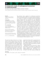
An overview of our FPGA implementation is illustrated in
Figure 1. We use two independent modules working in paral-
lel. Each module is implemented in a separate FPGA. While
one module performs the wavelet decomposition of an in-
put TV frame, the other module performs the inverse wavelet
transform of the previous TV frame. The two modules switch
their functionality in time. The wavelet-domain denoising
block is located in front of the inverse wavelet transform.
The proposed distributed algorithm implementation
over the two modules allows effective logic decentralization
with respect to input and output data streams. Namely, while
one FPGA module is handling the input video stream per-
forming the wavelet decomposition, the other FPGA mod-
ule is reading the wavelet coefficients for denoising, sending
them to the wavelet reconstruction, and building up the vi-
sually improved output video stream.
2.1. Memory organization
The nondecimated wavelet transform demands significant
memory resources. For example, in our implementation with
three decomposition levels we need to store nine frames of
wavelet coefficients for every input frame. In addition, we
need an input memory bufferandanoutputbuffer for iso-
lating data accesses from different clock domains.
The input data stream is synchronized with a 13.5 MHz
clock. For three decomposition levels the complete wavelet
decomposition and reconstruction has to be completed with
the clock of at least 3
× 13.5 = 40.5 MHz. The set-up of
our hardware platform requires the output data stream at
27 MHz. Tabl e 1 lists the required interfaces of the buffers
that are used in the system.
The most critical timing issue is at the memory buffer for
storing the wavelet coefficients. It has to provide simultane-
ous read and write options at 40.5 MHz. Due to lack of the
SDRAM controller that supports this timing issue, the whole
processing is split in two independent parallel modules. The
idea is to distribute the direct and the inverse wavelet process-
ing between these modules. While one module is performing
the wavelet decomposition of the current frame, the other
module is performing the inverse wavelet transform of the
Mihajlo Katona et al. 3
Wavelet coefficient RAM Wavelet coefficient RAM
40.5MHz 40.5MHz
Denoising Denoising
W
1
WW
1
WW
1
Control module Control module
Output buffer
Tem p oral
filter
Input buffer
Control module
27 MHz 13.5MHz
Figure 1: A detail of the FPGA implementation of the proposed wavelet-domain video denoising algorithm.
Table 1: Memory interfaces.
Buffers Write port (MHz) Read port (MHz)
Input buffer 13.5 40.5
Wavele t coefficients buffer 40.5 40.5
Output buffer 40.5 27
previous frame. With such organization, one module reads
and the other module writes the coefficients. The approxima-
tion subband (LL band) during the wavelet decomposition
and composition is stored in the onboard SRAM memory.
This allows us to use only read or write memory port during
one frame.
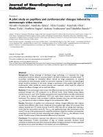
2.2. Data flow
The data flow through all the memory buffers and both
FPGA’s in our scheme is shown in Figure 2. The total delay
is 4 frames. During the first 20 milliseconds, the input frame
A
0
is stored in the input buffer at a clock rate of 13.5 MHz.
During the next 20 milliseconds, this frame is read from the
input buffer and is wavelet transformed in a 40.5 MHz clock
domain, with 3 decomposition scales W
1
(A
0
), W
2
(A
0
), and
W
3
(A
0
). In parallel to this process, the next frame A
1
is writ-
ten in the input buffer. The following time slot of 20 mil-
liseconds is currently not used for processing A
0
,butisre-
served for future a dditional processing in the wavelet do-
main. Within this period the frame A
1
is read from the in-
put buffer and is decomposed in its wavelet coefficients. The
frames A
0
and A
1
are processed by FPGA1. The next input
frame, A
2
, is written in the input buffer, and is wavelet trans-
formed in the next time frame by FPGA2.
The denoising and the inverse wavelet transform of the
frame A
0
are performed afterwards. During this period the
wavelet coefficients of the frame A
0
are read from the mem-
ory, denoised and the output frame is reconstructed with
the inverse wavelet transform W
−1
(A
0
). Dur ing the last re-
construction stage (the reconstruction at the finest wavelet
scale), the denoised output frame is written to the output
memory buffer. Parallel to this process, FPGA2 per forms the
wavelet decomposition of the frame A
2
and the input frame
A
3
is stored in the input buffer.
Finally, 4
× 20 milliseconds = 80 milliseconds after the
frame A
0
appeared at the system input (4 frames later), it
is read from the output buffer in a 27 MHz clock domain
and is sent to the selective recursive temporal filter and to the
system output afterwards. The output data stream is aligned
with a 100 Hz refresh rate, which means that the same frame
is sent twice to the output within one time frame of 20 mil-
liseconds. Additionally, FPGA2 performs the wavelet decom-
position of the frame A
3
. Further on, A
4
frame is written to
the input buffer and is decomposed in the following time
frame under the control of FPGA1.
In this scheme, the two FPGAs actually switch their func-
tionality after each two frames. The FPGA1 performs the
wavelet decomposition for two frames, while the FPGA2
performs the inverse wavelet transform of the previous two
frames. After two frames, this is reversed.
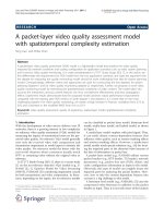
3. ALGORITHM CUSTOMIZATION FOR
REAL-TIME PROCESSING
We design an FPGA implementation of a sequantial spa-
tial/temporal video denoising scheme from [9], which is de-
picted in Figure 3. Note that we use an overcomplete (non-
decimated) wavelet transform to guarantee a high-quality
spatial denoising. In this representation, with three decom-
position levels the number of the wavelet coefficients is 9
times the input image size. Therefore we choose to perform
the temporal filtering in the image domain (after the in-
verse wavelet transform) in order to minimize the memory
requirements.
3.1. The customization of the wavelet transform
While hardware implementations of the orthogonal wavelet
transform have been extensively studied in literature [16–
21, 26, 27], much less research has been done towards
implementations of the nondecimated wavelet transform.
We develop a hardware implementation of the non-decimat-
ed wavelet transform based on the algorithm
`
a trous [30]and
with the classical three orientation subbands per scale. This
4 EURASIP Journal on Embedded Systems
Write
Read
In
A
0
A
1
A
2
A
3
A
4
A
5
A
6
A
7
A
1
A
0
A
1
A
2
A
3
A
4
A
5
A
6
Write
Read
Wavelet
FPGA1
W
1
(A
1
) W
1
(A
1
) W
1
(A
0
) W
2
(A
0
) W
3
(A
0
) W
1
(A
1
) W
2
(A
1
) W
3
(A
1
) W
1
(A
2
) W
1
(A
2
) W
1
(A
3
) W
1
(A
3
) W
1
(A
4
) W
2
(A
4
) W
3
(A
4
) W
1
(A
5
) W
2
(A
5
) W
3
(A
5
) W
1
(A
6
) W
1
(A
6
)
Write
Read
Wavelet
FPGA2
Write
Read
Out
W
3
(A
1
)W
2
(A
1
)W
1
(A
1
) W
1
(A
0
) W
2
(A
0
) W
1
(A
1
) W
2
(A
1
) W
3
(A
2
) W
2
(A
2
) W
1
(A
2
) W
3
(A
3
) W
2
(A
3
) W
1
(A
3
) W
1
(A
4
) W
2
(A
4
) W
1
(A
5
) W
2
(A
5
) W
3
(A
6
) W
2
(A
6
) W
1
(A
6
)
W
1
(A
3
)W
2
(A
3
)W
3
(A
3
) W
1
(A
2
) W
1
(A
2
) W
1
(A
1
) W
1
(A
1
) W
1
(A
0
) W
2
(A
0
) W
3
(A
0
) W
1
(A
1
) W
2
(A
1
) W
3
(A
1
) W
1
(A
2
) W
1
(A
2
) W
1
(A
3
) W
1
(A
3
) W
1
(A
4
)W
2
(A
4
)W
3
(A
4
)
W
1
(A
3
) W
2
(A
3
) W
3
(A
2
)W
2
(A
2
)W
1
(A
2
)W
3
(A
1
)W
2
(A
1
)W
1
(A
1
) W
1
(A
0
) W
2
(A
0
) W
1
(A
1
) W
2
(A
1
) W
3
(A
2
)W
2
(A
2
)W
1
(A
2
) W
3
(A
3
)W
2
(A
3
)W
1
(A
3
) W
1
(A
4
)W
2
(A
4
)
A
3
A
2
A
1
A
0
A
1
A
2
A
3
A
4
A
4
A
4
A
3
A
3
A
2
A
2
A
1
A
1
A
0
A
0
A
1
A
1
A
2
A
2
A
3
A
3
20 ms 20 ms 20 ms 20 ms 20 ms 20 ms 20 ms 20 ms
FPGA1 fields
FPGA2 fields
Direct wavelet transform
Inverse wavelet transform
W
j
(A
i
)-wavelet decompositions at scale j
W
1
(A
i
)-wavelet reconstruction of the frame A
i
A
j
-processing frame with index i
Figure 2: The data flow of wavelet processing.
2D wavelet
transform
Denoising by
wavelet
shrinkage
Inverse
2D wavelet
transform
Pixel-based
motion detector
Selective
recursive filter
Figure 3: The implemented denoising scheme.
algorithm upsamples the wavelet filters at each decomposi-
tion level. In particular, 2
j
−1 zeros (“holes,” in French, trous)
are inserted between the filter coefficients at the decomposi-
tion level j, as it is shown in Figure 4.
We use the SystemC library [31] and a previously devel-
oped simulation environment [32, 33] to develop a real-time
model of the wavelet decomposition and reconstruction.
Figure 5 shows the simulation model. After a number of
simulations and tests we have concluded that the real-time
wavelet implementation with 16 bit arithmetic gives practi-
cally the same results as a referent MATLAB code of the algo-
rithm
`
a trous [30]. At a number of input frames there were
more than 97.13% errorless pixels with mean error of 0.0287.
Analyzing those figures at the level of bit representation, we
can conclude that maximally 1 bit out of 16 was wrong. The
wrong bit may occur on the bit position 0 shown in Figure 6.
Taking into account that input pixels are 8 bit integers we can
ignore this error.
3.2. The pipelined FPGA implementation of
the nondecimated wavelet transform
Here we develop an FPGA implementation of a nondeci-
mated wavelet transform with three orientation subbands
per scale. We design FIR filters for the algorithm
`
a trous [30]
with the Daubechies’ minimum phase wavelet of length four
[34] and we implement the designed FIR filters with dedi-
cated multipliers in the Xilinx Virtex2 FPGAs [35].
Mihajlo Katona et al. 5
H
j
(z)
G
j
(z)
G
j
(z)
G
j
(z)
HH
HL
LH
LL
A
j+1
H
j
(z)
A
j
H
j
(z)
h
0
(n) = h[0]h[1]h[2]h[3]
h
1
(n) = h[0]0 h[1]0 h[2]0 h[3]
h
2
(n) = h[0]000 h[1]000 h[2]000 h[3]
g
0
(n) = g[0]g[1]g[2]g[3]
g
1
(n) = g[0]0 g[1]0 g[2]0 g[3]
g
2
(n) = g[0]000 g[1]000 g[2]000 g[3]
2
j
1 “trous” (holes) 2
j
1 “trous” (holes)
Figure 4: The nondecimated 2D discrete wavelet transform.
2D
wavelet
transformation
2D inverse
wavelet
transformation
Input
data
0
15
14 : 7
6:0
0
Output
data
LL
16
LH
16
HL
HH
16
16
16 16
15
14 : 7
6:0
88
Figure 5: The de veloped simulation model for the implementation of the wavelet transform.
Our implementation of the 2D wavelet transform is line-
based as shown in Figure 7. We choose the line alignment
in order to preserve the video sequence input format and to
pipeline the whole processing in our system. The horizontal
and the vertical filtering is performed within one pass of the
input video stream. We avoid using independent horizontal
and vertical processing which requires two cycles and an in-
ternal memory for storing the output of the horizontal filter-
ing. Instead, we use the line-based vertical filtering with as
many internal line buffers as there are taps in the used FIR
filter.
The horizontal and vertical FIR filters differ only in the
filter delay path implementation. The data path of the hor-
izontal filter is a register pipeline as shown in Figure 8.The
data path of the vertical filter is the output of the line buffers.
Hence, the vertical FIR filter does not include any delay ele-
ments, but only the pipelined filtering arithmetics (multipli-
ers and an adder). Pipelining the filtering arithmetics ensures
the requested timing for data processing and we use this ap-
proach both for the horizontal and vertical filters.
The algorithm
`
a trous [30] upsamples the wavelet filters
by inserting 2
j
− 1 zeros between the filter coefficients at the
decomposition level j (see Figure 4). We implement this fil-
ter up-sampling by using a longer filter delay path and the
appropriate data selection logic. The required number of the
registers depends on the length of the mother wavelet func-
tion and on the number of the decomposition levels used. We
use a wavelet of length four and three decomposition levels,
and hence our horizontal filter in Figure 8 contains 3
×4 = 12
registers. Four registers are dedicated to the 4-tap filter and
3 times as many are needed to implement the required up-
sampling up to the third decomposition level. Analogously,
on the vertical filtering side, each line buffer for vertical fil-
tering is able to store up to 4 lines.
For the calculation of the first decomposition level of the
wavelet transform, only the first 4 registers d0, d1, d2, and d3
in Figure 8 are used in the FIR filter register pipeline. At the
second decomposition level, the wavelet filters have to be up-
sampled with 1 zero between the filter coefficients. In our im-
plementation, this means that registers d0, d2, d4, and d6 are
used for filtering. Figure 8 illustrates the FIR filter configu-
ration during the calculation of the wavelet coefficients from
the third decomposition level. During this period, the d0, d4,
d8, and d12 registers are involved in the filtering process.
6 EURASIP Journal on Embedded Systems
0
0
Input
Output
0
X
0
X
0
X
0
X
0
X
0
X
0
X
FEDCBA987F543210
Figure 6: Input and output data format.
Video
input
4tap
horizontal FIR
L
4tap
horizontal FIR
H
Line buffer
Line buffer
Line buffer
Line buffer
Vertical FIR input select
4tap
vertical FIR
LL
4tap
vertical FIR
LH
4tap
vertical FIR
HL
4tap
vertical FIR
HH
LL
LH
HL
HH
Figure 7: A block schematic of the developed hardware implementation of the wavelet transform.
We implement the inverse wavelet transform accordingly.
The processing is mirrored when compared to the wavelet
decomposition: the vertical filtering is done first and the hor-
izontal processing afterwards. The FIR filter design is the
same as for the direct wavelet transform, only the filter co-
efficients a(0), a(1), a(2), and a(3) in Figure 8 are mirrored.
3.3. The wavelet shrinkage customization
Our video denoising scheme employs a spatially adaptive
wavelet shrinkage approach of [36]. A brief description of
this denoising method follows.
Let y
l
denote the noise-free wavelet coefficient and w
l
its
observed noisy version at the spatial position l in a given
wavelet subband. For compactness, we suppressed here the
indices that denote the scale and the orientation. The method
of [36] shrinks each wavelet coefficient by a factor which
equals the probability that this coefficient presents a signal of
interest. The signal of interest is defined as a noise-free signal
component that exceeds in magnitude the standard devia-
tion of noise σ. The probability of the presence of a signal
of interest at position l is estimated based on the coefficient
magnitude |w
l
| and based on a local spatial activity indicator
z
l
=
k∈∂
l
|w
k
|,where∂
l
is the neighborhood of the pixel
l (within a squared window) and N
l
is the number of the
neighboring coefficients. For example, for a 3
× 3 window
∂
l
consists of the 8 nearest neighbors of the pixel l (N
l
= 8).
Let H
1
denote the hypothesis “the signal of interest is
present:”
|y
l
| >σand let H
0
denote the opposite hypothesis:
“
|y
l
|≤σ.” The shrinkage estimator of [9]is
y
l
= P
H
1
| w
l
, z
l
w
l
=
ρξ
l
η
l
1+ρξ
l
η
l
w
l
,(1)
where
ρ
=
P
H
1
P
H
0
, ξ
l
=
p
w
l
| H
1
p
w
l
| H
0
, η
l
=
p
z
l
| H
1
p
z
l
| H
0
.
(2)
p(w
l
| H
0
)andp(w
l
| H
1
) denote the conditional prob-
ability density functions of the noisy coefficients given the
absence and given the presence of a signal of interest. Sim-
ilarly, p(z
l
| H
0
)andp(z
l
| H
1
) denote the corresponding
conditional probability density functions of the local spa-
tial activity indicator. The input-output characteristic of this
wavelet denoiser is illustrated in Figure 9. This figure shows
that the coefficients that are small in magnitude are strongly
shrinked towards zero, while the largest ones tend to be left
unchanged. The displayed family of the shrinkage character-
istics corresponds to the different values of the local spatial
activity indicator. For the same coefficient magnitude
|w
l
|
the input coefficient will be shrunk less if LSAI z
l
is bigger
and vice versa.
We now address the implementation of this shrinkage
function. Under the Laplacian prior for noise-free data
p(y)
= (λ/2) exp(−λ|y|)wehave[9] ρ = exp(−λT)/(1 −
exp(−λT)). The analytical expressions for ξ
l
and η
l
seem too
complex for the FPGA implementation. We efficiently imple-
ment the two likelihood ratios ξ
l
and η
l
as appropriate look-
up tables, stored in two “read-only” memories (ROM). The
generation of the particular look-up-tables is based on an ex-
tensive experimental study, as we explain later in this section.
The developed architecture is presented in Figure 10.One
ROM memory, containing the look-up table ξ
l
, is addressed
by the coefficient magnitude
|w
l
|, and the other ROM mem-
ory, containing the look-up table ρη
l
is addressed by LSAI
z
l
. For calculating LSAI, we average the coefficient values
from the current line and from the previous two lines within
Mihajlo Katona et al. 7
x(n)
Z
1
Z
1
Z
1
Z
1
Z
1
Z
1
Z
1
Z
1
Z
1
Z
1
Z
1
Z
1
Z
1
d0 d1 d2 d3 d4 d5 d6 d7 d8 d9 d10 d11 d12
Scale
= 3
a(0) a(1) a(2) a(3)
Z
1
Z
1
Z
1
Z
1
++ +
y(n)
Figure 8: The proposed FIR filter implementation of the algorithm
`
a trous for a mother wavelet of length 4 and supporting up to 3 de-
composition levels. The particular arithmetic network using the registers d0, d4, d8, and d12 corresponds to the calculation of the wavelet
coefficients at the third decomposition level.
150
100
50
0
50
100
150
150 100 50 0 50 100 150
Noisy input coefficient
Different LSAI
Figure 9: An illustration of the employed wavelet shrinkage family.
a3× 3 w indow. The read values from ROM’s are multi-
plied to produce the generalized likelihood ratio r
= ρξ
l
η
l
.
We fo und i t more efficient to realize the shrinkage factor
r/(1 + r) using another ROM (look-up-table) instead of us-
ing the arithmetic operations. The output of this look-up-
table denoted here as “shrinkage ROM” is the desired wavelet
shrinkage factor. Finally, the output of the shrinkage ROM
multiplies the input coefficient to yield the denoised coeffi-
cient.
We denoise in parallel three wavelet bands LH, HL, and
HH at each scale. Different resolution levels (we use three)
are processed sequentially as illustrated in Figure 2. The low-
pass (LL) band is only delayed for the number of clock peri-
ods that are needed for denoising. This delay, which is in our
implementation 6 clock cycles, ensures the synchronization
of the inputs at the inverse wavelet transform block (see the
timing in Figure 2).
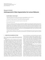
The generation of the appropriate look-up tables for the
two likelihood ratios resulted from our extensive experi-
ments on different test images and different noise-levels as
it is described in [29]. Figure 11 illustrates the likelihood ra-
tio ξ
l
calculated from one test image at different noise lev-
els. These diagrams show another interpretation of the well-
known threshold selection principle in wavelet denoising: a
well-chosen threshold value for the wavelet coefficients in-
creases with the increase of the noise level. The maximum
likelihood estimate of the threshold T (i.e., the value for
which p(T
| H
0
) = p(T | H
1
)) is the abscissa of the point
ξ
l
= 1. Figure 12 displays the likelihood ratio ξ
l
, in the di-
agonal subband HH at third decomposition level, for 10 dif-
ferent frames with fixed noise standard deviations (σ
= 10
and σ
= 30). We showed in [29] that from a practical point
of view, the difference between the calculated likelihood ra-
tios for different frames is minor, especially for lower noise
levels (up to σ
= 20). Therefore we average the likelihood ra-
tios over different frames and store these values as the corre-
sponding look-up tables for several different noise levels (σ
=
5, 10, 15, and 20). In the denoising procedure, the user selects
the input noise level, which enables addressing the correct set
of the look-up tables. The performance loss of the algorithm
due to simplifications w ith the generated look-up tables is for
different input noise levels shown in Figure 13. These results
8 EURASIP Journal on Embedded Systems
FIFO
(line buffer)
FIFO
(line buffer)
LSAI coefficient
magnitude window
Z
1
Z
1
Z
1
Z
1
Z
1
Z
1
Z
1
Z
1
Z
1
+
(1
scale)ABS(pixel)
(1
scale)
Energy
8
Address generation
combinatorial network
ROM
ROM
KSI
ETA
Shrinkage
ROM
Output
coefficient
Input
coefficient
Figure 10: Block schematic of implemented denoising architecture.
1000
900
800
700
600
500
400
300
200
100
0
0 50 100 150 200 250
HH
Figure 11: Likelihood ratio ξ
l
for one test frame and 4 different
noise levels (σ
= 5, 10, 20, 30).
represent peak signal-to-noise ratio (PSNR) values averaged
over frames of several different video sequences. For σ
= 10
the average performance loss was only 0.13 dB (and visually,
the differences are difficult to notice) while for σ
= 20 the
performance loss is 0.55 dB and is on most frames becom-
ing visually noticeable, but not highly disturbing. For high er
noise levels, the performance loss increases.
In the current implementation, the user has to select one
of the available noise levels. With such approach, i t is possi-
ble that the user will not choose the best possible noise re-
duction. If the selected noise level is smaller from the real
noise level in the input signal, some of the noise will remain
in the output signal. On the other hand, if the noise level is
over-estimated, the output signal will be blurred without sat-
isfying visual effect.
This user intervention can be avoided by implementing a
noise level estimator. The output of this block could be used
for the look-up table selection, which further enables ad-
justable noise reduction according to the noise level in input
signal. For example, a robust wavelet-domain noise estimator
based on the median absolute deviation [37]canbeusedfor
this purpose or other related wavelet-domain noise estima-
tors like [38].
The likelihood ratios ξ
l
and η
l
are monotonic increasing
functions. We are currently investigating the approximation
of these functions by a family of piece-wise linear functions
parameterized by the noise standard deviation and by the pa-
rameter of the marginal statistical distribution of the noise-
free coefficients in a given subband.
3.4. Temporal filtering
A pixel-based motion detector with selec tive recursive tem-
poral filtering is quite simple for hardware implementation.
Since we first apply a high quality spatial filtering the noise is
already significantly suppressed and thus a pixel-based mo-
tion detection is efficient. In case the motion is detected the
recursive filtering is switched off.
Two pixels are involved for temporal filtering at a time:
one pixel from the current field and another from the same
spatial position in the previous field. We store the two fields
in the output buffer and read the both required pixel values
in the same cycle. If the absolute difference between these two
pixel values is smaller than the predefined threshold value,
no motion case is assumed and the two pixel values are sub-
ject to a weighted averaging, with the weighting factors de-
fined in [9]. In the other case, when motion is detected, the
current pixel is passed to the output. The block schematic in
Figure 14 depicts the developed FPGA architecture of the se-
lective recursive temporal filter described above. We use the
8 bit arithmetic because the filter is located in the time do-
main where all the pixels are represented as 8 bit integers.
4. REAL-TIME ENVIRONMENT
In our implementation we use the standard television broad-
casting signal as a source of video signal. A common feature
of all standard TV broadcasting technologies is that the video
sequence is transmitted in a nalog domain (this excludes the
latest DVB and HDTV transmission standards). Thus, before
digital processing of television video sequence the digitaliza-
tion is needed. Also, after digital processing the sequence has
tobeconvertedbacktotheanaloguedomaininorderto
be shown on a standard tube display. This pair of A/D and
D/A converters is well known as a codec. The 8 bit codec,
with 256 levels of quantization per pixel, is considered suf-
ficient from the visual quality point of view. Figure 15 shows
a block schematic of digital processing for television broad-
casting systems.
We use the PAL-B broadcasting standard and 8 bit YUV
4 : 2 : 2 codec. The hardware platform set-up consists of
Mihajlo Katona et al. 9
1000
900
800
700
600
500
400
300
200
100
0
0 50 100 150 200 250
HH
(a)
1000
900
800
700
600
500
400
300
200
100
0
0 50 100 150 200 250 300
HH
(b)
Figure 12: Likelihood ratio ξ
l
displayed for 10 frames with fixed-noise levels: σ = 10 (a) and σ = 30 (b).
50
40
30
20
10
0
510152030
Standard deviation of added noise
40.39
40.23
35.77
35.63
33.24
32.95
31.55
31.00
29.22
27.98
PSNR (dB)
Original with 3 decomposition levels
FPGA implementation
PSNR comparison
Figure 13: Performance of the designed FPGA implementation in comparison with the original software version of the algorithm, which
employs exact analytical calculation of the involved shrinkage expression.
three separate boards. Each board corresponds to one of the
blocks presented in Figure 15:
(i) Micronas IMAS-VPC 1.1 (A/D—analog front-end)
[39];
(ii) CHIPit Professional Gold Edition (processing block)
[40];
(iii) Micronas IMAS-DDPB 1.0 (D/A—analog back-end)
[41].
We made all the connections among the previously men-
tioned boards with a separate interconnection board designed
for this purpose. This interconnection board consists of the
interconnection channels and the voltage adjustments be-
tween the CHIPit board (3.3 V level) and the Micronas IMAS
boards (5 V level).
The processing board consists of two Xilinx Virtex II
FPGAs (XC2V6000-5) [35] and is equipped with plenty of
SDRAM memory (6 banks with 32 bit access made with
256 Mbit ICs).
All boards of the used hardware platform are c onfigured
with the I2C interface. The user is able to set up the needed
noise level in input signal. This is fulfilled with writing ap-
propriate value to the corresponding register in the FPGA
accessible via the I2C interface. Appropriate look-up table
with the averaged likelihood ratio is selected according to the
valueinthisregister.
5. CONCLUSION
We designed a real-time FPGA implementation of an ad-
vanced wavelet-domain video denoising algorithm. The de-
veloped hardware architecture is based on innovative techni-
cal solutions that allow an implementation of sophisticated
adaptive wavelet denoising in hardware. We believe that the
results reported in this paper can be interesting for a num-
ber of industrial applications, including TV broadcasting
systems. Our current implementation has limitations in
practical use due to the required user-intervention for noise
level estimation. Our future work will integrate the noise
level e stimation to avoid these limitations and to allow au-
tomatic adaptation of the denoiser to the noise level changes
in the input signal.
10 EURASIP Journal on Embedded Systems
Delay
Pixel from
current field
Pixel from
previous field
ABS (A-B)
A<B
+
Output
0.6
0.4
Threshold
Figure 14: Block schematic of implemented temporal filter.
A/D
X
1
(nT)
Input
video
sequence
nT
Digital
processing
X
2
(nT)
nT
D/A
Output
video
sequence
Figure 15: A digital processing system for television broadcasting video sequences.
ACKNOWLEDGMENT
The second author is a Postdoctoral Researcher of the Fund
for the Scientific Research in Flanders (FWO), B elgium.
REFERENCES
[1] F. Cocchia, S. Carrato, and G. Ramponi, “Design and real-
time implementation of a 3-D rational filter for edge preserv-
ing smoothing,” IEEE Transactions on Consumer Electronics,
vol. 43, no. 4, pp. 1291–1300, 1997.
[2] G. Arce, “Multistage order statistic filters for image sequence
processing,” IEEE Transactions on Signal Processing, vol. 39,
no. 5, pp. 1146–1163, 1991.
[3] V. Zlokolica and W. Philips, “Motion and detail adaptive de-
noising of video,” in Image Processing: Algorithms and Systems
III, vol. 5298 of Proceedings of SPIE, pp. 403–412, San Jose,
Calif, USA, January 2004.
[4] L. Hong and D. Brzakovic, “Bayesian restoration of image se-
quences using 3-D Markov random fields,” in Proceedings of
the IEEE International Conference on Acoustics, Speech and Sig-
nal Processing (ICASSP ’89), vol. 3, pp. 1413–1416, Glasgow,
UK, May 1989.
[5] J. Brailean and A. Katsaggelos, “Simultaneous recursive dis-
placement estimation and restoration of noisy-blurred image
sequences,” IEEE Transactions on Image Processing, vol. 4, no. 9,
pp. 1236–1251, 1995.
[6] P. van Roosmalen, S. Westen, R. Lagendijk, and J. Biemond,
“Noise reduction for image sequences using an oriented pyra-
mid thresholding technique,” in IEEE International Conference
on Image Processing, vol. 1, pp. 375–378, Lausanne, Switzer-
land, September 1996.
[7] I. Selesnick and K. Li, “Video denoising using 2D and 3D dual-
tree complex wavelet transforms,” in Wavelets: Applications in
Signal and Image Processing X, vol. 5207 of Proceedings of SPIE,
pp. 607–618, San Diego, Calif, USA, August 2003.
[8] D. Rusanovskyy and K. Egiazarian, “Video denoising algo-
rithm in sliding 3d dct domain,” in Proceedings of the 7th
International Conference on Advanced Concepts for Intelligent
Vision Systems (ACIVS ’05), J. Blanc-Talon, W. Philips, D.
Popescu, and P. Scheunders, Eds., vol. 3708 of Lecture N otes on
Computer Science, pp. 618–625, Antwerp, Belgium, September
2005.
[9] A. Pi
ˇ
zurica, V. Zlokolica, and W. Philips, “Noise reduction
in video s equences using wavelet-domain and temporal filter-
ing,” in Wavelet Applications in Industrial Processing, vol. 5266
of Proceedings of SPIE, pp. 48–59, Providence, RI, USA, Octo-
ber 2003.
[10] V. Zlokolica, A. Pi
ˇ
zurica, and W. Philips, “Video denois-
ing using multiple class averaging with multiresolution,” in
The International Workshop on Very Low Bitrate Video Coding
(VLBV ’03), pp. 172–179, Madrid, Spain, September 2003.
[11] B. A. Draper, J. R. Beveridge, A. P. W. Bohm, C. Ross, and
M. Chawathe, “Accelerated image processing on FPGAs,” IEEE
Transactions on Image Processing, vol. 12, no. 12, pp. 1543–
1551, 2003.
[12] A. M. Al-Haj, “Fast discrete wavelet transformation using FP-
GAs and distributed arithmetic,” International Journal of Ap-
pliedScienceandEngineering, vol. 1, no. 2, pp. 160–171, 2003.
[13] G. Goslin, “A guide to using field programmable gate arrays
(FPGAs) for application-specific digital signal processing per-
formance,” XILINX Inc., 1995.
[14] C. Dick, “Implementing area optimized narrow-band FIR fil-
ters using Xilinx FPGAs,” in Configurable Computing: Technol-
og y and Applications, vol. 3526 of Proceedings of SPIE, pp. 227–
238, Boston, Mass, USA, November 1998.
[15] R. D. Tur ney, C. Dick, and A. Reza, “Multirate filters and
wavelets: from theory to implementation,” XILINX Inc.
[16] J. Ritter and P. Molitor, “A pipelined architecture for parti-
tioned DWT based lossy image compression using FPGA’s,” in
ACM/SIGDA International Symposium on Field Programmable
Gate Arrays (FPGA ’01), pp. 201–206, Monterey, Calif, USA,
February 2001.
Mihajlo Katona et al. 11
[17] M. Nibouche, A. Bouridane, F. Murtagh, and O. Nibouche,
FPGA-Based Discrete Wavelet Transforms System,Schoolof
Computer Science, The Queen’s University of Belfast, Belfast,
UK, 2001.
[18] M. A. Trenas, J. Lopez, and E. L. Zapata, “FPGA implemen-
tation of wavelet packet transform with reconfigurable tree
structure,” in Proceedings of the 26th Euromicro Conference
(EUROMICRO ’00), pp. 1244–1251, Maastricht, The Nether-
lands, September 2000.
[19] K. Wiatr and P. Russek, “Embedded zero wavelet coefficient
coding method for FPGA implementation of v ideo codec in
real-time systems,” in The International Conference on Infor-
mation Technology: Coding and Computing (ITCC ’00),pp.
146–151, Las Vegas, Nev, USA, March 2000.
[20] S. G. Mathen, “Wavelet tr ansform based adaptive image com-
pression on FPGA,” M.S. thesis, University of Kansas, Manhat-
tan, Kan, USA, 2000.
[21] J. B. Ballagh, “An FPGA-based run-time reconfigurable 2-D
discrete wavelet transform core,” M.S. thesis, Virginia Poly-
technic Institute, Blacksburg, Va, USA, 2001.
[22] L. Nachtergaele, B. Vanhoof, M. Pe
´
on,G.Lafruit,J.Bor-
mans, and I. Bolsens, “Implementation of a scalable MPEG-4
wavelet-based visual texture compression system,” in Proceed-
ings of the 36th Design Automation Conference (DAC ’99),pp.
333–336, New Orleans, La, USA, June 1999.
[23] A. R. Calderbank, I. Daubechies, W. Sweldens, and B L. Yeo,
“Wavelet transforms that map integers to integers,” Applied
and Computational Harmonic Analysis, vol. 5, no. 3, pp. 332–
369, 1998.
[24] W. Sweldens, “Lifting scheme: a new philosophy in biorthog-
onal wavelet constructions,” in Wavelet Applications in Signal
and Image Processing III, vol. 2569 of Proceedings of SPIE,pp.
68–79, San Diego, Calif, USA, July 1995.
[25] W. Sweldens, “Wavelets and the lifting scheme: a 5 minute
tour,” Zeitsc hrift f
¨
ur Angewandte Mathematik und Mechanik,
vol. 76, no. 2, pp. 41–44, 1996.
[26]G.Dillen,B.Georis,J D.Legat,andO.Cantineau,“Com-
bined line-based architecture for the 5-3 and 9-7 wavelet
transform of JPEG2000,” IEEE Transaction on Circuits and Sys-
tems for Video Technology, vol. 13, no. 9, pp. 944–950, 2003.
[27] B F. Wu and Y Q. Hu, “An efficient VLSI implementation
of the discrete wavelet transform using embedded instruction
codes for sy mmetric filters,” IEEE Transactions on Circuits and
Systems for Video Technology, vol. 13, no. 9, pp. 936–943, 2003.
[28] M. Katona, A. Pi
ˇ
zurica, V. Zlokolica, N. Tesli
´
c, and W. Philips,
“Real-time wavelet domain video denoising implemented in
FPGA,” in Wavelet Applications in Industrial Processing II,
vol. 5607 of Proceedings of SPIE, pp. 63–70, Philadelphia, Pa,
USA, October 2004.
[29] M. Katona, A. Pi
ˇ
zurica, N. Tesli
´
c, V. Kovacevic, and W. Philips,
“FPGA design and implementation of a wavelet-domain video
denoising system,” in Proceedings of the 7th International Con-
ference on Advanced Concepts for Intelligent Vision Systems
(ACIVS ’05), J. Blanc-Talon, D. Popescu, W. Philips, and P.
Scheunders, Eds., vol. 3708 of Lecture Notes on Computer Sci-
ence, pp. 650–657, Antwerp, Belgium, September 2005.
[30] S. Mallat and S. Zhong, “Characterization of signals from mul-
tiscale edges,” IEEE Transactions on Pattern Analysis and Ma-
chine Intelligence, vol. 14, no. 7, pp. 710–732, 1992.
[31] SystemC Version 2.0 Users Guide, SystemC Inc., 2002,
http://
www.systemc.org.
[32] M.Katona,N.Tesli
´
c, V. Kovacevic, and M. Temerinac, “Test
environment for bluetooth baseband inegrated circuit devel-
opment,” in Proceedings of the 5th International Conference on
Telecommunications in Modern Satellite, Cable and Broadcast-
ing Services (TELSIKS ’01),B.D.Milovanovic,Ed.,vol.2,pp.
405–408, Nis, Yoguslavia, Septmeber 2001.
[33] M. Katona, N. Tesli
´
c, and Z. Krajacevic, “FPGA design w ith
SystemC,” in The 10th International Conference on Mixed
Design of Integrated Circuits and Systems (MIXDES ’03),A.
Napieralski, Ed., vol. 1, pp. 220–223, Lodz, Poland, June 2003.
[34] I. Daubechies, TenLecturesonWavelets, SIAM, Philadelphia,
Pa, USA, 1992.
[35] Virtex II Platform FPGA: Complete Data Sheet, XILINX Inc.,
2004, .
[36] A. Pi
ˇ
zurica and W. Philips, “Estimating the probability of the
presence of a signal of interest in multiresolution single- and
multiband image denoising,” IEEE Transactions on Image Pro-
cessing, vol. 15, no. 3, pp. 654–665, 2006.
[37] D. L. Donoho and I. M. Johnstone, “Adapting to unknown
smoothness via wavelet shrinkage,” Journal of the American
Statistical Association, vol. 90, no. 432, pp. 1200–1224, 1995.
[38] V. Zlokolica, A. Pi
ˇ
zurica, and W. Philips, “Noise estimation
for video processing based on spatial-temporal gradient his-
tograms,” to appear in IEEE Signal Processing Letters.
[39] VPC 3205C Video Processor Family, ITT Semiconductors: ITT
Intermetall, 1997, .
[40] CHIPit Gold Edition Handbook, ProDesign Electronic & CAD
Layout, 2003, .
[41] DDPB 3310B Display and Deflection Processor, Micronas Inter-
metal, 1998, .
Mihajlo Katona was born in 1974, in Vr-
bas, Yugoslavia. In 1999, he received the
Diploma degree in computer engineering
and in 2001, M. S. degree in computer
science both from the University of Novi
Sad (Serbia and Montenegro). In 1999, he
joined the Chair for Computer Engineer-
ing at the University of Novi Sad, where he
is currently working as a Teaching Assis-
tant in the “design of complex digital sys-
tems.” He is currently pursuing his Ph.D. thesis. His research in-
terests include digital signal processing, DSP algorithm customiza-
tion for hardware implementation, system-on-chip architectures,
and FPGA prototyping.
Aleksandra Pi
ˇ
zurica wasborninNoviSad,
Yugoslavia, on September 18, 1969. In 1994,
she received the Diploma deg ree in elect ri-
cal engineering from the University of Novi
Sad, Yugoslavia, in 1997 the M.S. degree in
telecommunications from the University of
Belgrade, Yugoslavia, and in 2002 the Ph.D.
degree from the Ghent University, Belgium.
Since 1994 until 1997, she was working at
the Department of Telecommunications of the University of Novi
Sad, and in 1997 she joined the Department of Telecommunica-
tions and Information Processing of the Ghent University. She is
the author of 15 papers in international journals and more than
50 papers at international scientific conferences. Her research in-
terests include image restoration, multiresolution representations,
Markov random field models, signal detection and estimation,
multimedia applications, and remote sensing.
12 EURASIP Journal on Embedded Systems
Nikola Tesli
´
c is a Professor at the Chair
for Computer Engineering, Faculty of En-
gineering, University of Novi Sad, Serbia
and Montenegro. In 1995, he received the
Diploma degree in electrical engineering
from the University of Novi Sad, Yugoslavia,
in 1997 the M.S. degree in computer engi-
neering, and in 1999 the Ph.D. degree from
the University of Novi Sad, Serbia and Mon-
tenegro. Currently he lectures in the “design
of complex digital systems” and “software for TV sets and image
processing” and “DSP architectures and algorithms.” His scientific
interests are in the area of computer engineering, especially in the
area of real-time systems, electronic computer-based systems, digi-
tal system for audio-video processing. He is the author of 6 papers
in international journals and more than 50 papers at international
scientific conferences.
Vladimir Kova
ˇ
cevi
´
c is a Professor and he
leads the Chair for Computer Engineering,
Faculty of Engineering , University of Novi
Sad, Yugoslavia. Currently he lectures in
the “design of complex digital systems” and
“computer systems design.” He received his
Ph.D. degree at the University of Belgrade.
His scientific interests are in the areas of
computer engineering, especially in the area
of real-time systems, electronic computer-
based systems, large-scale digital system design, computer systems
design, communication networks, and systems programming.
Wilfried Philips wasborninAalst,Belgium
on October 19, 1966. In 1989, he received
the Diploma degree in elect rical engineer-
ing and in 1993 the Ph.D. degree in applied
sciences, both from the University of Ghent,
Belgium. Since November 1997, he is a Lec-
turer at the Department of Telecommuni-
cations and Information Processing of the
University of Ghent. His main research in-
terests are image and video restoration and
analysis and data compression. He is the author of more than 50
papers in international journals and 200 papers in the proceedings
of international scientific conferences, the Editor of 8 conference
proceedings and 1 special issue of a journal. He has received 10
national and internal awards for his research. He coorganizes 2 in-
ternational conferences in the area of image and v ideo processing
and computer vision and is a member of the program committee
of several national and international workshops.