Báo cáo hóa học: " Research Article 60-GHz Millimeter-Wave Radio: Principle, Technology, and New Results" pptx
Bạn đang xem bản rút gọn của tài liệu. Xem và tải ngay bản đầy đủ của tài liệu tại đây (1.05 MB, 8 trang )
Hindawi Publishing Corporation
EURASIP Journal on Wireless Communications and Networking
Volume 2007, Article ID 68253, 8 pages
doi:10.1155/2007/68253
Research Article
60-GHz Millimeter-Wave Radio: Principle,
Technology, and New Results
Nan Guo,
1
Robert C. Qiu,
1, 2
Shaomin S. Mo,
3
and Kazuaki Takahashi
4
1
Center for Manufacturing Research, Tennessee Technological University (TTU), Cookeville, TN 38505, USA
2
Department of Electrical and Computer Engineering, Tennessee Technological University (TTU), Cookeville, TN 38505, USA
3
Panasonic Princeton Laboratory (PPRL), Panasonic R&D Company of America, 2 Research Way, Princeton, NJ 08540, USA
4
Network Development Center, Matsushita Electric Industrial Co., Ltd., 4-12-4 Higashi-shinagawa, Shinagawa-ku,
Tokyo 140-8587, Japan
Received 15 June 2006; Revised 13 September 2006; Accepted 14 September 2006
Recommended by Peter F. M. Smulders
The worldwide opening of a massive amount of unlicensed spectra around 60 GHz has triggered great interest in developing af-
fordable 60-GHz radios. This interest has been catalyzed by recent advance of 60-GHz front-end technologies. This paper briefly
reports recent work in the 60-GHz radio. Aspects addressed in this paper include global regulatory and standardization, justifi-
cation of using the 60-GHz bands, 60-GHz consumer electronics applications, radio system concept, 60-GHz propagation and
antennas, and key issues in system design. Some new simulation results are also given. Potentials and problems are explained in
detail.
Copyright © 2007 Nan Guo et al. T his is an open access article distributed under the Creative Commons Attribution License,
which permits unrestricted use, distribution, and reproduction in any medium, provided the original work is properly cited.
1. INTRODUCTION
During the past few years, substantial knowledge about the
60-GHz millimeter-wave (MMW) channel has been accu-
mulated and a great deal of work has been done toward
developing MMW communication systems for commercial
applications [1–16]. In 2001, the Federal Communications
Commission (FCC) allocated 7 GHz in the 57–64 GHz band
for unlicensed use. The opening of that big chunk of free
spectrum, combined with advances in wireless communica-
tions technologies, has rekindled interest in this portion of
spectrum once perceived for expensive point-to-point (P2P)
links. The immediately seen opportunities in this particular
region of spectrum include next-generation wireless personal
area networks (WPANs). Now a question raises: do we really
need to use the 60-GHz band? The answer is yes and in the
next sect ion we will explain this in detail. The bands around
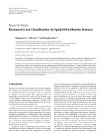
60 GHz are worldwide available and the most recent global
60-GHz regulatory results are summarized in Figure 1 and
Table 1.
The high frequencies are associated with both advantages
and disadvantages. High propagation attenuation at 60 GHz
(following the classic Friis formula) actually classifies a set of
short-range applications, but it also means dense frequency
reuse patterns. Higher frequencies lead to smaller sizes of RF
components including antennas. At MMW frequencies, not
only are the antennas very small, but also they can be quite
directional (coming with high antenna gain), which is highly
desired. The cost concern is mainly related to the transceiver
RF front ends. Traditionally, the expensive III–V semicon-
ductors such as gallium arsenide are required for MMW ra-
dios [3–5, 12]. In the past few years, alternative semiconduc-
tor technologies have been explored [6–10, 13]. According to
the reports about recent progress in developing the 60-GHz
front-end chip sets [15], IBM engineers have demonstrated
the first experimental 60-GHz transmitter and receiver chips
using a high-speed alloy of silicon and germanium (SiGe);
meanwhile researchers from UCLA, UC Berkeley Wireless
Research Center (BWRC), and other universities or institutes
are using a widely available and inexpensive complemen-
tary metal oxide semiconductor (CMOS) technology to build
60-GHz transceiver components. Each of the two technolo-
gies has advantages and disadvantages. But it was claimed by
IBM that its SiGe circuit models worked surprisingly well at
60 GHz. It is no doubt that the SiGe versus CMOS debate will
continue.
Two organizations that drive the 60-GHz radios are the
IEEE standard body [17] and WiMedia alliance, an industrial
2 EURASIP Journal on Wireless Communications and Networking
Australia
Canada
and USA
Japan
Europe
57 58 59 60 61 62 63 64 65 66
Frequency (GHz)
59.462.9
57 64
59
66
57
66
Figure 1: Spectra available around 60 GHz.
Table 1: Emission power requirements.
Region Output power Other considerations
Australia 10 mW into antenna 150 W peak EIRP
Canada and USA
500 mW peak min. BW = 100 MHz
Japan
10 mW into antenna
47 dBi max. ant. Gain
+50, −70% power change OT and TTR
Europe +57 dBm EIRP min. BW = 500 MHz
association [18]. The IEEE 802.15.3 Task Group 3c (IEEE
802.15.3c) is developing an MMW-based alternative phys-
ical layer (PHY) for the existing 802.15.3 WPAN Standard
IEEE-Std-802.15.3-2003. With merging of former multiband
OFDM alliance (MBOA), the WiMedia alliance is pushing
a 60-GHz WPAN industrial standard, likely based on or-
thogonal frequency division multiplexing (OFDM) technol-
ogy. The shooting data rate is 2 Gb/s or higher. Among a
large number of proposals, the majority of them can be cat-
egorized to either multicarrier (meaning OFDM) or single-
carrier types, where the former is expected to support ex-
tremely high data rates (say, up to 10 Gb/s; see Section 6.1
for explanation).
The rest of this paper is organized as follows. Section 2
explains why the 60-GHz radio is necessary. Potential ap-
plications of the 60-GHz radio are introduced in Section 3 .
Radio system concept is discussed in Section 4. Section 5 re-
ports recent work on the 60-GHz channel modeling, and
identifies an issue of the directional antenna impact on the
medium access control (MAC) sublayer. In Section 6, a list
of system design issues is discussed, followed by conclusions
given in Section 7.
2. WHY IS THE 60-GHZ BAND ATTRACTIVE?
The answer is multifold. First of all, data rates or band-
widths are never enough, while the wireless multimedia dis-
tribution market is ever growing. Let us take a look at the
microwave ultra-wideband (UWB) impulse radio [19–24].
UWB is a revolutionary power-limited technology for its un-
precedented system bandwidth in the unlicensed band of
3.1–10.6 GHz allocated by FCC. The low emission and im-
pulsive nature of the UWB radio leads to enhanced secu-
rity in communications. Through-wall penetration capabil-
ity makes UWB systems suitable for hostile indoor environ-
ments. The UWB impulse radio can be potentially imple-
mented with low-cost and low-power consumption (battery
driven) components. UWB is able to deliver high-speed mul-
timedia wirelessly and it is suitable for WPANs. However, one
of the most challenging issues for UWB is that international
coordination regarding the operating spectrum is difficult to
achieve among major countries. In addition, the IEEE stan-
dards are not accepted worldwide. This spectral difficulty will
deeply shape the landscape of WPANs in the future. Spec-
trumallocation,however,seemsnottobeanissuefor60-
GHz WPANs. This is one of the reasons for the popularity of
60-GHz MMW.
Inter-system interference is another concern. The UWB
band is overlaid over the 2.4- and 5-GHz unlicensed bands
used for increasingly deployed WLANs, thus the mutual in-
terferences would be getting worse and worse. This inter-
system interference problem exists in Europe and Japan too.
In order to protect the existing wireless systems operating
in different regions, regulatory bodies in these regions are
working on their own requirements for UWB implementa-
tion. Worldwide harmonization around 60 GHz is possible,
but it is almost impossible for a regional UWB radio to work
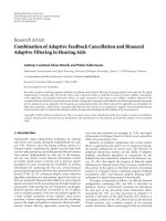
in another region. Figure 2 shows two spectral masks that set
emission power limits in US and Japan. Unlicensed use in
Japan is permitted at the 3.4–4.8 GHz and 7.25–10.25 GHz
wireless spectra, the latter of which is reserved for indoor
products only. Products using the lower 3.4–4.8 GHz spec-
trum will be required to implement detection and avoidance
(DAA) technologies to avoid interference with other services
operating at the same frequencies. When spectrum conflict is
detected, the UWB signal strength has to be dropped.
Data-rate limitation is also a concern. Currently, the
multiband OFDM (MB-OFDM) UWB systems can provide
maximum data rate of 480 MB/s. This data rate can only sup-
port compressed video. Data rate for uncompressed video
for high definition TV, such as high-definition multimedia
interface (HDMI), can easily go over 2 Gb/s. Although the
Nan Guo et al. 3
10 20 30 40 50 60 70 80 90 100 110
10
2
100
80
60
40
20
dBm/MHz
DAA is
required
1400 M
3000 M
Indoor
products only
3400 4800 7250 10250
FCC mask for indoor UWB
Japanese UWB mask
Figure 2: Emission power limits in US and Japan.
Table 2: Relationship between center frequencies and coverage
range.
Band group Center frequency (MHz) Range ( meter)
1 3, 960 10.0
2
5, 544 5.10
3
7, 128 3.09
4
8, 712 2.07
5
10, 032 1.56
MB-OFDM UWB can be enhanced to support 2 Gb/s, the
complexity, power consumption, and cost will increase ac-
cordingly.
Finally, variation of received signal strength over a given
spectrum can be a bothering factor. For the MB-OFDM
UWB systems, there are 5 band groups covering a frequency
range from 3.1 GHz to 10.6 G Hz. According to the Friis prop-
agation rule, given the same transmitted power, propagation
attenuation is inversely proportional to the square of a group
center frequency. If band group 1 can cover 10 meters, cover-
age range for band group 5 is only 1.56 meters (see Ta ble 2).
On the other hand, because of relatively smaller change in
frequency, coverage range does not change dynamically for
the 60-GHz radio.
Therefore, the 60-GHz band is indeed an underexploited
waterfront.
3. POTENTIAL CONSUMER ELECTRONICS
APPLICATIONS AT 60 GHZ
Similar to the microwave UWB radio, the 60-GHz radio is
suitable for high-data-rate and short-distance applications,
but it suffers from less chance of inter-system interference
than the UWB. People believe that the 60-GHz radio can
find numerous applications in residential areas, offices, co n-
ference rooms, corridors, and libraries. It is suitable for in-
home applications such as audio/video transmission, desk-
top connection, and support of portable devices. Judging by
the interest shown by many leading CE and PC companies,
applications can be divided into the fol l owing categories:
(i) high definition video streaming,
(ii) file transfer,
(iii) wireless Gigabit Ethernet,
(iv) wireless docking station and desktop point to multi-
point connections,
(v) wireless backhaul,
(vi) wireless ad hoc networks.
The first three, that is, high definition video streaming, file
transfer, and wireless Gigabit Ethernet, are considered as top
applications. In each category, there are different use cases
based on (1) whether they are used in residential area or of-
fice, (2) distance between the transmitters and receivers, (3)
line-of-sight (LOS) or non-line-of-sight (NLOS) connection,
(4) position of the transceivers, and (5) mobility of the de-
vices. In [25], 17 use cases have been defined.
High-definition video streaming includes uncompressed
video streaming for residential use. Uncompressed HDTV
video/audio stream is sent from a DVD player to an HDTV.
Typical distance between them is 5 to 10 meters with ei-
ther LOS or NLOS connection. The high-definition streams
can also come out from portable devices such as laptop
computer, personal data assistant (PDA), or portable media
player (PMP) that are placed somewhere in the same room
with an HDTV. In this setting, coverage range might be 3 to
5 meters with either LOS or NLOS connection. NLOS results
from that the direct propagation path is temporarily blocked
by human bodies or objects. Uncompressed video streaming
can also be used for a laptop-to-projector connection in con-
ference room where people can share the same projector and
easily connect to the projector without switching cables as in
the case of cable connection.
File transfer has more use cases. In offices and residential
areas it can happen between a PC and its peripherals includ-
ing printers, digital cameras, camcorders, and so forth. It may
also happen between portable devices such as PDA and PMP.
A possible application may be seen in a kiosk in a store that
sells audio/video contents. Except for connections between
fixed devices, such as a PC and its peripherals, where NLOS
may be encountered temporarily, most use cases involving
portable devices should be able to have LOS connections be-
cause these devices can be moved to adjust aiming.
4. SYSTEM CONCEPT OF 60-GHZ RADIO
The system can be described in different ways. The system
core is built m ainly on physical layer and MAC sublayer. Typ-
ical MAC functions include multiple access, radio resource
management, rate adaptation, optimization of transmission
parameters, and quality of s ervice (QoS), and so forth. When
antenna arrays are employed, the MAC needs to support ad-
ditional functions like probing, link set up, and maintenance.
The physical layer part of a transceiver contains an RF
front end and a baseband back end. What should be high-
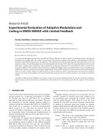
lighted in the front end is the multistage signal conversion.
Taking an example from IBM’s report [16], illustrated in
Figure 3 is an MMW receiver front-end architecture with
two-stage down conversion, where “
×3” is a frequency tripler
(a type of frequency multiplier) and “
÷2” is a frequency di-
vider with factor 2. The phase lock loop (PLL) with voltage
4 EURASIP Journal on Wireless Communications and Networking
controlled oscillator (VCO) generates a frequency higher
than that of the reference source. The multiplier increases
the frequency further. The RF signal is converted from RF
to intermediate frequency (IF) and then to baseband. The re-
sulted IF signal after the first down conversion has a lower
center frequency thus is easy to handle. The second-stage
conversion is quadrature down conversion leading to a pair
of baseband outputs. In the transmitter front end, up con-
version is achieved in a reversed procedure. Multistage sig-
nal conversion is an implementation approach which is as-
sociated with insertion loss contributed by multiple mixers.
In addition, conversion between baseband and 60 GHz in-
troduces an increased phase noise. If desired frequency at
the input of the mixer is f and the original frequency from
the reference source is f
0
, then the final phase noise will
be 20 log
10
( f/f
0
) dB stronger than the original level, with-
out taking into account additional phase noise contributed
by circuits. This is why phase noise enlargement could be a
problem to the 60-GHz radio.
An antenna arr ay technique called phased array [26–
30] has been considered feasible for the 60-GHz radio. The
phased array relies on RF phase rotators to achieve beam
steering. One benefit of using antenna array is that the re-
quirements for power amplifiers (PAs) can be reduced. Ac-
cording to reports from BWRC, CMOS amplifier gain at
60GHzisbelow12dB[2],whichraisesaconcernaboutlim-
ited transmitted power. Note that the transmitter-side an-
tenna array automatically achieves spatial power combining
[2]. Figure 4 is a transmitter configuration with a phased ar-
ray and a bank of PAs, where each branch contains a phase
rotator, a PA, and an antenna element. If each branch can
emit a certain amount of power, an M-branch transmitter
can provide roughly 20 log
10
M dB more power at the re-
ceiver, compared to the case of a single-antenna transmitter.
To see some quantitative results, a set of simulations have
been conducted considering the following setting:
(i) center frequency: 60 GHz,
(ii) modulation: OQPSK,
(iii) symbol duration: 1 nanosecond (bit ra te 2 Gb/s),
(iv) shaping filter: square-root r aised cosine (SR-RC) with
roll-off factor 0.3,
(v) PA: Rapp model with gain
= 12, smooth factor = 2,
and 1 dB compression input power
= 7 dBm (assum-
ing 50 ohm input impedance),
(vi) antenna type: single-directional antenna at both Tx
and Rx with 7 dBi gain,
(vii) channel model: LOS channel with no multipath,
(viii) transmit power (EIRP): 8.85 dBm,
(ix) low-noise amplifier gain: 12 dB,
(x) receiver noise figure: 10 dB,
(xi) detection method: matched filter.
This setting meets the emission power requirements in all
regions. To isolate phase noise issue, it is intentionally to
use the one-path channel model and to prevent the sig-
nal from being clipped by the PA. The PA’s input power is
about
−10.15 dBm which is far below the assumed 1 dB com-
pression power (7 dBm), implying that the PA’s nonlinearity
Image-reject
LNA
63 GHz
RF
mixer
54 GHz
3
18 GHz
Reference
PLL
IF Amp.
9GHz
2
9GHz
IF mixer
π/2
0GHz
BB Amp.
I
Q
Figure 3: A proposed RF front-end architecture [16].
Data and
control
Transmitter
Phase
rotator
Phase
rotator
Phase
rotator
.
.
.
PA
PA
PA
Receiver
Figure 4: BER versus distance for different levels of phase noise.
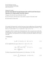
would be negligible for this specific setting. The impact of
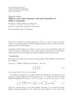
phase noise on bit-error rate (BER) can be seen in Figure 5,
where the abscissa represents the transmission distance be-
tween the transmitter and receiver. Basically, when phase-
noise level is above
−85 dBc at 1 MHz, it is not able to sup-
port a bit rate of 2 Gbps using OQPSK (or QPSK). It can be
imaged that higher-order phase modulation or quadrature
modulation would be more sensitive to phase noise. These
results suggest that phase noise is a big obstacle to increasing
data rate or extending distance.
5. PROPAGATION AND ANTENNA EFFECT
60-GHz channel characteristics have been well studied in
the past. References [31–40] are some of most recent ex-
perimental work in uncovering the behavior of the chan-
nels. It has been noted that the channels around 60 GHz
do not exhibit r ich multipath, and the non-line-of-sight
(NLOS) components suffer from tremendous attenuation.
These channel characteristics are in favor of reducing mul-
tipath effect, but makes communications difficult in NLOS
environments. With a plenty of measurement contributions,
the IEEE 802.15.3c is currently working to set the statisti-
cal description of a 60-GHz S-V channel model based upon
contributed empirical measurements. Shown in Tab le 3 is a
summary of measured data [40]. Proposed by NICT (Yoko-
suka, Japan) is an enhanced S-V channel model called TSV
model, and in the case of LOS it contains two paths. A set
Nan Guo et al. 5
5 10 1520253035
Distance (m)
10
6
10
5
10
4
10
3
10
2
10
1
10
0
BER
65 dBc @ 1 MHz
75 dBc @ 1 MHz
80 dBc @ 1 MHz
85 dBc @ 1 MHz
90 dBc @ 1 MHz
95 dBc @ 1 MHz
Figure 5: BER versus distance for different levels of phase noise.
Table 3: Summary of measured data.
Source Measured environments AoA
Office desktop (N)LOS
1
NICTA Office corridor (N)LOS
1
Yes
Closed office (N)LOS
1
NICT Japan
Empty residential (N)LOS
1
Yes
Open-plan office NLOS
Office cubicles
LOS, NLOS
Yes
University of
Office corridor
Massachusetts Closed office
Homes
IMST Library LOS, NLOS Virtual
2
Cluttered residential LOS, NLOS
France Telecom Open-plan office LOS, NLOS Virtual
2
Conference room LOS, NLOS
Library LOS, NLOS
IBM Office cubicles LOS, NLOS No
Cluttered residential LOS, NLOS
1
Inherent NLOS component due to directionality of the antenna.
2
Data measured over linear and grid arrays.
of 10-channel models have been proposed and the map-
pings between environments and channel models are listed
in Table 4 [25].
At 60 GHz, the antennas are in centimeter or sub-
centimeter size, and achieving 10 dBi antenna gain is prac-
tical, which encourages us to use directional antennas since a
high antenna gain (equivalently, narrow antenna pattern or
high directivity) is desired to improve the signal-to-noise ra-
tio (SNR) and reduce inter-user interference. However, the
60-GHz radio is sensitive to shadowing due to high attenua-
tion of NLOS propagation, and the directional antennas can
Table 4: Mapping of environment to channel model.
Channel model Scenario Environment name
CM1 LOS
Office
CM2
NLOS
CM3 LOS Desktop
CM4 LOS
Residential
CM5
NLOS
CM6 LOS
Conference room
CM7
NLOS
CM8 LOS Corridor
CM9 LOS
Library
CM10
NLOS
make it more problematic when the LOS path is blocked and
in the scenarios that require mobility without aiming. In or-
der to cover all directions of interest while providing certain
antenna gain, two beam steering solutions, antenna switch-
ing/selection (simple beam steering method) [41]andphase-
array antennas [2, 26–30], have been suggested. To cooperate
with beam forming or steering, traditional M AC designed for
omni-directional antennas is no longer optimal [42, 43]. One
open research topic is cross-layer optimization considering
the impact of antenna directivity on the MAC.
6. SYSTEM DESIGN ISSUES
This section does not discuss system design systematically,
but goes through some issues involved in the system design.
6.1. Single carrier versus multicarrier
Here by multicarrier we mean OFDM. OFDM is an effec-
tive means to mitigate multipath effect, although it has dis-
advantages of high peak-to-average power ratio, higher sen-
sitivity to the phase noise [44], and relatively high power
consumption at the transmitter. According to some 60-GHz
channel measurement reports, the NLOS components suffer
from much higher losses than the LOS component. LOS con-
nection appears in many suggested application scenarios. In
addition, directional antennas and beam steering are highly
recommended for the 60-GHz radio. All these facts suggest
that at 60 GHz, mitig ation of multipath effect is not the
number-one issue, and the single-car rier approach should
be comparable to its multicarrier counterpart in terms of
spectral efficiency. However, the multicarrier approach in-
deed has some advantages from implementation point of
view: the transceiver can be efficiently implemented using
IFFT/FFT, and frequency-domain equalization is rather easy
and flexible. At this point, the single-carrier approach is con-
sidered for low-end applications. For example, single-carrier
transmission with on-off keying (OOK) modulation should
have no problem to support data rates up to 2 Gb/s over an
LOS link of 2-GHz bandw idth, and it can be chosen to build
low-cost wireless devices. Higher data rate can be expected
if wider bandwidth or multiband is utilized. If both single
6 EURASIP Journal on Wireless Communications and Networking
carrier and multicarrier solutions are accepted, compatibil-
ity between them is an issue.
6.2. Selection of modulation schemes
The following factors need to be considered in selecting
modulation scheme: spectral efficiency, linearity of power
amplifier (PA), phase-noise level, and scalability, and so
forth. Plotted in Figure 6 are spectra of several modulation
signals with different pulse shaping, w here “SR-RC” stands
for “square-root raised cosine,” T
S
is the symbol duration
and each symbol contains two bits, and the Gaussian fil-
ter for GMSK has a 3-dB bandwidth of 0.3/T
S
. Among the
modulation schemes considered in Figure 6, only GMSK and
OQPSK/QPSK with SR-RC shaping can provide fast spec-
tral roll off.IfB is one-sided bandwidth of modulated signal,
the bandwidth efficiency is equal to 1/(T
S
B) symbols/s/Hz.
Obviously, none of GMSK and OQPSK/QPSK with SR-RC
shaping can achieve a 2-bits/s/Hz (or 1-symbol/s/Hz) band-
width efficiency. Illustrated in Figure 7 is the trajectory of
a segment of OQPSK signal with roll-off factor 0.3. It can
be seen in Figure 7 that the trajectory is no longer a square
(OQPSK with rectangular shaping has a square trajectory).
The shaping filter for bandwidth efficiency ac tually makes
the amplitude more fluctuating (a purely constant-envelop
modulation scheme, such as MSK, has a circle trajectory).
QPSK is convenient to be down scaled to BPSK or up scaled
to 8 PSK. Because of relatively high-phase noise at 60 GHz
(due to limited Q-value, the achievable phase noise is around
−85 dBc/Hz at 1 MHz frequency offset [2]), higher order
modulation schemes such as 16 QAM would be too challeng-
ing.
Though OOK is not a bandwidth-efficient modulation,
it is a very good candidate for l ow-cost devices since OOK-
modulated signal can be noncoherently demodulated using
cheap circuit. In addition, O O K does not require linear PA,
so that large power back off is not necessary and the PA would
be very efficient in terms of power consumption. GMSK is a
constant-envelop modulation scheme with fast roll-off prop-
erty, and it is the best choice for using maximally the PA
(assuming single carrier), but its theoretical bandwidth ef-
ficiency is around 1.33 bits/s/Hz. Also, at the bit rate of a few
Gigabits/s, it is not clear at present whether or not the Viterbi
algorithm (for GMSK demodulation) can be implemented at
acceptable price.
6.3. Other issues
It is desired to reuse IEEE 802.15.3 MAC for the 60-GHz
radio. Potential impacts on the MAC come from high-data
rate, high-antenna directivity, shadowing, and maybe com-
patibility between single carrier and multicar rier. Chance
of signal blocking is good in indoor LOS-dominated en-
vironments, especially when beam forming or steering are
employed. In other words, fast acquiring and maintain-
ing a reliable link is critical to the 60-GHz radio. Effec-
tively implementing these functions is very challenging and
it needs involvement of both PHY and MAC. Dual-band
(microwave and MMW) operation was proposed as a mea-
00.51 1.522.5
f
T
S
150
100
50
0
dB
Normalized power spectra
OQPSK/QPSK, rectanglar shaping
OQPSK/QPSK,SR-RC,roll-off factor
= 0.3
MSK
GMSK, 3-dB bandwidth
= 0.3/T
S
Gaussian filter, 3-dB bandwidth = 0.3/T
S
Figure 6: Spectra of different modulation schemes.
0.3 0.2 0.10 0.10.20.3
ln-phase amplitude
0.3
0.2
0.1
0
0.1
0.2
0.3
Quadrature amplitude
Signal trajectory
Figure 7: Trajectory of OQPSK with square-root raised cosine
shaping (roll-off factor
= 0.3; based on a simulation of 100 random
symbols).
sure against both coverage limitation and se vere shadowing
[1]. Possible dual-band combinations include WiFi/MMW
and UWB/MMW. Obviously, dual-band operation would in-
crease complexity at both PHY and MAC, implying a higher-
cost solution. When pulse-based low-duty-cycle signaling
is employed, some uncoordinated multiple-access methods
canbemoreefficient than CSMA/CA. Such multiple-access
Nan Guo et al. 7
methods include rate-division multiple access (RDMA) [45]
and delay-capture-based multiple access [46–48]. All of these
pose challenges for optimal design of MAC.
7. CONCLUSIONS
The 60-GHz radio has been discussed in different aspects.
Positive moves can be seen in standardization and front-end
development. Though potential is clear, there are many prob-
lems. Technically, success of the 60-GHz radio will largely de-
pend on the advance of 60-GHz front-end technology. The
SiGe versus CMOS debate will continue and it is not clear
when we will see high-speed front ends with acceptable price.
There are many questions to answer in designing PHY and
MAC. Here are some examples: single carrier or multicar-
rier, or both? what kind of modulation? how to optimally
control antennas from MAC? Breakthroughs in beam form-
ing or steering and low-phase-noise local oscillator (LO) are
expected. It will be very likely that the future mar ket of the
60-GHz radio will be a mixture of varieties covering a full
range of applications from low end to high end.
ACKNOWLEDGMENT
This work was supported in part by Panasonic R&D Com-
pany of America, Panasonic Princeton Laboratory (PPRL).
REFERENCES
[1] P. Smulders, “Exploiting the 60 GHz band for local wire-
less multimedia access: prospects and future directions,” IEEE
Communications Magazine, vol. 40, no. 1, pp. 140–147, 2002.
[2] C.H.Doan,S.Emami,D.A.Sobel,A.M.Niknejad,andR.W.
Brodersen, “Design considerations for 60 GHz CMOS radios,”
IEEE Communications Magazine, vol. 42, no. 12, pp. 132–140,
2004.
[3] H. Daembkes, B. Adelseck, L. P. Schmidt, and J. Schroth,
“GaAs MMIC based components and frontends for millime-
terwave communication and sensor systems,” in Proceedings of
IEEE Microwave Systems Conference (NTC ’95), pp. 83–86, Or-
lando, Fla, USA, May 1995.
[4] R. L. Van Tuyl, “Unlicensed millimeter wave communications
a new opportunity for MMIC technology at 60 GHz,” in Pro-
ceedings of the 18th Annual IEEE Gallium Arsenide Integrated
Circuit Symposium, pp. 3–5, Orlando, Fla, USA, November
1996.
[5] M. Siddiqui, M. Quijije, A. Lawrence, et al., “GaAs compo-
nents for 60 GHz wireless communication applications,” in
Proceedings of GaAs Mantech Conference,SanDiego,Calif,
USA, April 2002.
[6] S. Reynolds, B. Floyd, U. Pfeiffer, and T. Zwick, “60 GHz
transceiver circuits in SiGe bipolar technology,” in IEEE In-
ternat ional Solid-State Circuits Conference. Digest of Technical
Papers (ISSCC ’04), vol. 1, pp. 442–538, San Francisco, Calif,
USA, February 2004.
[7] C. H. Doan, S. Emami, A. M. Niknejad, and R. W. Brodersen,
“Design of CMOS for 60 GHz applications,” in IEEE Interna-
tional Solid-State Circuits Conference. Digest of Technical Papers
(ISSCC ’04), vol. 1, pp. 440–538, San Francisco, Calif, USA,
February 2004.
[8] W. Winkler, J. Borngr
¨
aber,H.Gustat,andF.Kornd
¨
orfer, “60
GHz transceiver circuits in SiGe:C BiCMOS technology,” in
Proceedings of the 30th European Solid-State Circuits Conference
(ESSCIRC ’04), pp. 83–86, Leuven, Belgium, September 2004.
[9] S. K. Reynolds, “A 60-GHz superheterodyne downconversion
mixer in Silicon-Germanium bipolar technology,” IEEE Jour-
nal of Solid-State Circuits, vol. 39, no. 11, pp. 2065–2068, 2004.
[10] B. A. Floyd, S. K. Reynolds, U. R. Pfeiffer,T.Zwick,T.
Beukema, and B. Gaucher, “SiGe bipolar transceiver circuits
operating at 60 GHz,” IEEE Journal of Solid-State Circuits,
vol. 40, no. 1, pp. 156–167, 2005.
[11] N. Depar is, A. Bendjabballah, A. Boe, et al., “Transposition
of a baseband UWB signal at 60 GHz for high data rate in-
door WLAN,” IEEE Microwave and Wireless Components Let-
ters, vol. 15, no. 10, pp. 609–611, 2005.
[12] S. E. Gunnarsson, C. K
¨
arnfelt, H. Zirath, et al., “Highly in-
tegrated 60 GHz transmitter and receiver MMICs in a GaAs
pHEMT technology,” IEEE Journal of Solid-State Circuits,
vol. 40, no. 11, pp. 2174–2185, 2005.
[13] S. Pinel, C H. Lee, S. Sarkar, et al., “Low cost 60 GHz Gb/s
radio development,” in Progress in Electromagnetics Research
Symposium, pp. 483–484, Cambridge, Mass, USA, March
2006.
[14] S. Sarkar, P. Sen, S. Pinel, C. H. Lee, and J. Laskar, “Si-based
60GHz 2X subharmonic mixer for multi-Gigabit wireless per-
sonal area network application,” in Proceedings of IEEE MTT-
S International Microwave Symposium, San Francisco, Calif,
USA, June 2006.
[15] S. K. Moore, “Cheap chips for next wireless frontier,” IEEE
Spectrum, vol. 43, pp. 12–13, 2006.
[16] B. Gaucher, “Completely integrated 60 GHz ISM band front
end chip set and test results,” IEEE 802.15 TG3c document:
15-06-0003-00-003c, January 2006.
[17] IEEE 802.15 Working Group for WPAN, e802.
org/15/.
[18] WiMedia alliance, />[19] R. Scholtz, “Multiple access with time-hopping impulse mod-
ulation,” in Proceedings of IEEE Military Communications Con-
ference (MILCOM ’93), vol. 2, pp. 447–450, Boston, Mass,
USA, October 1993.
[20] M. Z. Win and R. A. Scholtz, “Ultra-wide bandwidth time-
hopping spread-spectrum impulse radio for wireless multiple-
access communications,” IEEE Transactions on Communica-
tions, vol. 48, no. 4, pp. 679–689, 2000.
[21] R. C. Qiu, H. Liu, and X. Shen, “Ultra-wideband for multi-
ple access communications,” IEEE Communications Magazine,
vol. 43, no. 2, pp. 80–87, 2005.
[22] R. C. Qiu, R. A. Scholtz, and X. Shen, “Guest editorial special
section on ultra-wideband wireless communications—a new
horizon,” IEEE Transactions on Vehicular Technology, vol. 54,
no. 5, pp. 1525–1527, 2005.
[23] X. Shen, M. Guizani, H H. Chen, R. C. Qiu, A. F. Molisch,
and L. B. Milstein, “Guest editorial ultra-wideband wireless
communications—theory and applications,” IEEE Journal on
Selected Areas in Communications, vol. 24, no. 4, pp. 713–716,
2006, editorial on special issue on UWB.
[24] R. C. Qiu, X. Shen, M. Guizani, and T. Le-Ngoc, “Introduc-
tion,” in UWB Wireless Communications, X. Shen, M. Guizani,
R. C. Qiu, and T. Le-Ngoc, Eds., John Wiley & Sons, New York,
NY, USA, 2006.
[25] A. Sadri, “802.15.3c Usage Model Document (UMD), Draft,”
IEEE 802.15 TG3c document: 15-06-0055-14-003c, January
2006.
8 EURASIP Journal on Wireless Communications and Networking
[26] J. Park, Y. Wang, and T. Itoh, “A 60 GHz integrated an-
tenna array for high-speed digital beamforming applications,”
/>[27] A. Hajimiri, A. Komijani, A. Natarajan, R. Chunara, X. Guan,
and H. Hashemi, “Phased array s ystems in silicon,” IEEE Com-
munications Magazine, vol. 42, no. 8, pp. 122–130, 2004.
[28] X. Guan, H. Hashemi, and A. Hajimiri, “A fully integratted
24-GHz eight-element phased-array receiver in silicon,” IEEE
Journal of Solid-State Circuits, vol. 39, no. 12, pp. 2311–2320,
2004.
[29] H. Hashemi, X. Guan, A. Komijani, and A. Hajimiri, “A
24-GHz SiGe phased-array receiver - LO phase-shifting ap-
proach,” IEEE Transactions on Microwave Theor y and Tech-
niques, vol. 53, no. 2, pp. 614–626, 2005.
[30] A. Natarajan, A. Komijani, and A. Hajimiri, “A fully integrated
24-GHz phased-array transmitter in CMOS,” IEEE Journal of
Solid-State Circuits, vol. 40, no. 12, pp. 2502–2514, 2005.
[31] M. R. Williamson, G. E. Athanasiadou, and A. R. Nix, “Inves-
tigating the effects of antenna directivity on wireless indoor
communication at 6O GHz,” in Proceedings of the 8th IEEE In-
ternational Symposium on Personal, Indoor and Mobile Radio
Communications (PIMRC ’97), vol. 2, pp. 635–639, Helsinki,
Finland, September 1997.
[32] D. Dardari and V. Tralli, “High-speed indoor wireless commu-
nications at 60 GHz with coded OFDM,” IEEE Transactions on
Communications, vol. 47, no. 11, pp. 1709–1721, 1999.
[33] H. Xu, V. Kukshya, and T. S. Rappaport, “Spatial and temporal
characteristics of 60-GHZ indoor channels,” IEEE Journal on
Selected Areas in Communications, vol. 20, no. 3, pp. 620–630,
2002.
[34] A. G. Siamarou, “Broadband wireless local-area networks at
millimeter waves around 60 GHz,” IEEE Antennas and Propa-
gation Magazine, vol. 45, no. 1, pp. 177–181, 2003.
[35] C. R. Anderson and T. S. Rappaport, “In-building wideband
partition loss measurements at 2.5 and 60 GHz,” IEEE Trans-
actions on Wireless Communications, vol. 3, no. 3, pp. 922–928,
2004.
[36] F. Aryanfar and K. Sarabandi, “A millimeter-wave scaled mea-
surement system for wireless channel characterization,” IEEE
Transactions on Microwave Theor y and Techniques, vol. 52,
no. 6, pp. 1663–1670, 2004.
[37] S. Collonge, G. Zaharia, and G. El Zein, “Influence of the hu-
man activity on wide-band characteristics of the 60 GHz in-
door radio channel,” IEEE Transactions on Wireless Communi-
cations, vol. 3, no. 6, pp. 2396–2406, 2004.
[38] N. Moraitis and P. Constantinou, “Indoor channel measure-
ments and characterization at 60 GHz for wireless local area
network applications,” IEEE Transactions on Antennas and
Propagation, vol. 52, no. 12, pp. 3180–3189, 2004.
[39] T. Zwick, T. J. Beukema, and H. Nam, “Wideband channel
sounder with measurements and model for the 60 GHz in-
door radio channel,” IEEE Transactions on Vehicular Technol-
ogy, vol. 54, no. 4, pp. 1266–1277, 2005.
[40] A. Mathew, “Channel model status report,” IEEE 802.15 TG3c
document: IEEE 802.15-06/0037r2, May 2006.
[41] P.F.M.Smulders,M.H.A.J.Herben,andJ.George,“Appli-
cation of five-sector beam antenna for 60 GHz wireless LAN,”
/>[42] R. Ramanathan, J. Redi, C. Santivanez, D. Wiggins, and S.
Polit, “Ad hoc networking with directional antennas: a com-
plete system solution,” IEEE Journal on Selected Areas in Com-
munications, vol. 23, no. 3, pp. 496–506, 2005.
[43] F. Dai and J. Wu, “Efficient broadcasting in ad hoc wireless net-
works using directional antennas,” IEEE Transactions on Paral-
lel and Distributed Systems, vol. 17, no. 4, pp. 335–347, 2006.
[44] T. Pollet, M. Van Bladel, and M. Moeneclaey, “BER sensitivity
of OFDM systems to carrier frequency offset and Wiener phase
noise,” IEEE Transactions on Communications, vol. 43, no. 234,
pp. 191–193, 1995.
[45] M. Weisenhorn and W. Hirt, “Uncoordinated rate-division
multiple-access scheme for pulsed UWB signals,” IEEE Trans-
actions on Vehicular Technology, vol. 54, no. 5, pp. 1646–1662,
2005.
[46] D. H. Davis and S. A. Gronemeyer, “Performance of slotted
ALOHA random access with delay capture and randomized
time of arrival,” IEEE Transactions on Communications Sys-
tems, vol. 28, no. 5, pp. 703–710, 1980.
[47] K. Cheun, “Optimum arrival-time distribution for delay cap-
ture in spread-spectrum packet radio networks,” IEEE Trans-
actions on Vehicular Technology, vol. 46, no. 4, pp. 981–991,
1997.
[48] N. Guo, R. C. Qiu, and B. M. Sadler, “A UWB radio net-
work using multiple delay capture enabled by time reversal,”
in Proceedings of Military Communications Conference (MIL-
COM ’06), Washington, DC, USA, October 2006.