Báo cáo hóa học: " Research Article Energy-Efficient Acceleration of MPEG-4 Compression Tools" potx
Bạn đang xem bản rút gọn của tài liệu. Xem và tải ngay bản đầy đủ của tài liệu tại đây (1.12 MB, 18 trang )
Hindawi Publishing Corporation
EURASIP Journal on Embedded Systems
Volume 2007, Article ID 28735, 18 pages
doi:10.1155/2007/28735
Research Article
Energy-Efficient Acceleration of MPEG-4 Compression Tools
Andrew Kinane, Daniel Larkin, and Noel O’Connor
Centre for Digital Video Processing, Dublin City University, Glasnevin, Dublin 9, Ireland
Received 1 June 2006; Revised 21 December 2006; Accepted 6 January 2007
Recommended by Antonio Nunez
We propose novel hardware accelerator architectures for the most computationally demanding algorithms of the MPEG-4 video
compression standard-motion estimation, binary motion estimation (for shape coding), and the forward/inverse discrete co-
sine transforms (incorporating shape adaptive modes). These accelerators have been designed using general low-energy design
philosophies at the algorithmic/architectural abstraction levels. The themes of these philosophies are avoiding waste and t rading
area/performance for power and energy gains. Each core has been synthesised targeting TSMC 0.09 μm TCBN90LP technology,
and the exper imental results presented in this paper show that the proposed cores improve upon the prior art.
Copyright © 2007 Andrew Kinane et al. This is an open access article distributed under the Creative Commons Attribution
License, which permits unrestricted use, distribution, and reproduction in any medium, provided the original work is properly
cited.
1. INTRODUCTION
Whilst traditional forms of frame-based video are challeng-
ing in their own right in this context, the situation becomes
even worse when we look to future applications. In applica-
tions from multimedia messaging to gaming, users will re-
quire functionalities that simply cannot be supported with
frame-based video formats, but that require access to the
objects depicted in the content. Clearly this requires object-
based video compression, such as that supported by MPEG-
4, but this requires more complex and computationally de-
manding video processing. Thus, whilst object-video coding
has yet to find wide-spread deployment in real applications,
the authors believe that this is imminent and that this ne-
cessitates solutions for low-power object-based coding in the
short term.
1.1. Object-based video
Despite the wider range of applications possible, object-
based coding has its detractors due to the difficulty of the
segmentation problem in general. However, it is the belief of
the authors that in a constrained application such as mo-
bile video telephony, valid assumptions simplify the seg-
mentation problem. Hence certain object-based compres-
sion applications and associated benefits become possible. A
screenshot of a face detection algorithm using simple RGB
thresholding [1] is shown in Figure 1 . Although video ob-
ject segmentation is an open research problem, it is not the
main focus of this work. Rather, this work is concerned with
the problem of compressing the extracted video objects for
efficient transmission or storage as discussed in the next sec-
tion.
1.1.1. MPEG-4: object-based encoding
ISO/IEC MPEG-4 is the industrial standard for object-based
video compression [2]. Earlier video compression standards
encoded a frame as a single rectangular object, but MPEG-
4 extends this to the semantic object-based paradigm. In
MPEG-4 video, objects are referred to as video objects
(VOs) and these are irregular shapes in general but may
indeed represent the entire rectangular frame. A VO will
evolve temporally at a certain frame rate and a snapshot
of the state of a particular VO at a particular time instant
is termed a video object plane (VOP). The segmentation
(alpha) mask defines the shape of the VOP at that instant
and this mask also evolves over time. A generic MPEG-4
video codec is similar in structure to the codec used by
previous standards such as MPEG-1 and MPEG-2 but has
additional functionality to support the coding of objects
[3].
The benefits of an MPEG-4 codec come at the cost of
algorithmic complexity. Profiling has shown that the most
computationally demanding (and power consumptive) algo-
rithms are, in order: ME, BME, and SA-DCT/IDCT [4–6].
2 EURASIP Journal on Embedded Systems
Figure 1: Example face detection based on colour filtering.
A deterministic breakdown analysis is impossible in this in-
stance because object-based MPEG-4 has content-dependent
complexity. The breakdown is also highly dependent on the
ME strategy employed. For instance, the complexity break-
down between ME, BME, and SA-DCT/IDCT is 66%, 13%,
and 1.5% when encoding a specific test sequence using a
specific set of codec parameters and full search ME with
search window
±16 pixels [6]. The goal of the work pre-
sented in this paper is to implement these hotspot algorithms
in an energy-efficient manner, which is vital for the suc-
cessful deployment of an MPEG-4 codec on a mobile plat-
form.
1.2. Low-energy design approach
Hardware architecture cores for computing video processing
algorithms can be broadly classified into two categories: pro-
grammable and dedicated. It is generally accepted that dedi-
cated architectures achieve the greatest silicon and power ef-
ficiency at the expense of flexibility [4]. Hence, the core ar-
chitectures proposed in this paper (for ME, BME, SA-DCT,
and SA-IDCT) are dedicated architectures. However, the au-
thors argue that despite their dedicated nature, the proposed
cores are flexible enough to be used for additional multime-
dia applications other than MPEG-4. This point is discussed
in more detail in Section 6.
The low-energy design techniques employed for the pro-
posed cores (see Sections 2–5) are based upon three general
design philosophies.
(1) Most savings are achievable at the higher levels of de-
sign abstraction since wider degrees of freedom exist
[7, 8].
(2) Avoid unnecessary computation and circuit switching
[7].
(3) Trade performance (in terms of area and/or speed) for
energy gains [7].
Benchmarking architectures is a challenging task, espe-
cially if competing designs in the literature have been im-
plemented using different technologies. Hence, to evaluate
the designs proposed in this paper, we have used some nor-
malisations to compare in terms of power and energy and
a technology-independent metric to evaluate area and delay.
Each of these metrics are briefly introduced here and are used
in Sections 2–5.
1.2.1. Product of gate count and computation cycles
The product of gate count and computation cycles (PGCC)
for a design combines its latency and area properties into a
single metric, where a lower PGCC represents a better im-
plementation. The clock cycle count of a specific architec-
ture for a given task is a fair representation of the delay when
benchmarking, since absolute delay (determined by the clock
frequency) is technology dependent. By the same rationale,
gate count is a fairer metric for circuit area when benchmark-
ing compared to absolute area in square millimet res.
1.2.2. Normalised power and energy
Any attempt to normalise architectures implemented with
two different technologies is effectively the same process as
device scaling because all parameters must be normalised ac-
cording to the scaling ru les. The scaling formula when nor-
malising from a given process L to a reference process L
is
given by L
= S × L,whereL is the transistor channel length.
Similarly, the voltage V is scaled by a factor U according to
V
= U × V.
With the scaling factors established, the task now is to
investigate how the various factors influence the power P.
Using a first order approximation, the power consumption
of a circuit is expressed as P
∝ CV
2
fα,whereP depends on
the capacitive load switched C, the voltage V, the operating
frequency f , and the node switching probability α. Further
discussion about how each parameter scales with U and S
can be found in [9]. This reference shows that nor malising P
with respect to α, V, L,and f is achieved by (1),
P
= P × S
2
× U. (1)
With an expression for the normalised power consump-
tion established by (1), the normalised energy E
consumed
by the proposed design with respect to the reference technol-
ogy is expressed by (2), where D is the absolute delay of the
circuit to compute a given task and C is the number of clock
cycles required to compute that task,
E
= P
× D = P
×
1
f
× C. (2)
Another useful metric is the energy-delay product (EDP),
which combines energy and delay into a single metric. The
normalised EDP is given by (3),
EDP
= P
× D
2
. (3)
This section has presented four metrics that attempt
to normalise the power and energy properties of circuits
for b enchmarking. These metrics a re used to benchmark
the MPEG-4 hardware accelerators presented in this paper
against prior art.
Andrew Kinane et al. 3
2. MOTION ESTIMATION
2.1. Algorithm
Motion estimation is the most computationally intensive
MPEG-4 tool, requiring over 50% of the computational
resources. Although different approaches to motion estima-
tion are possible, in general the block-matching algorithm
(BMA) is favoured. The BMA consists of two tasks: a block-
matching task carrying out a distance criteria evaluation and
a search task specifying the sequence of candidate blocks
where the distance criteria is calculated. Numerous distance
criteria for BMA have been proposed, with the sum-of-
absolute-differences (SAD) criteria proved to deliver the best
accuracy/complexity ratio particularly from a hardware im-
plementation perspective [6].
2.2. Prior art review
Systolic-array- (SA-) based architectures are a common solu-
tion proposed for block-matching-based ME. The approach
offers an attractive solution, having the benefit of using
memory bandwidth efficiently and the regularity allows sig-
nificant control circuitry overhead to be eliminated [10]. De-
pending on the systolic structure, a SA implementation can
be classified as one-dimensional (1D) or two-dimensional
(2D), with global or local accumulation [11]. Clock rate,
frame size, search range, and block size are the parameters
used to decide on the number of PEs in the systolic structure
[10].
The short battery life issue has most recently focused
research on oper ation redundancy-free BM-based ME ap-
proaches. They are the so-called fast exhaustive search strate-
gies and they employ conservative SAD estimations (thresh-
olds) and SAD cancellation mechanisms [12, 13]. Further-
more, for heuristic (non-regular) search strategies (e.g., log-
arithmic searches), the complexity of the controller needed
to generate data addresses and flow control signals increases
considerably along with the power inefficiency. In order
to avoid this, a tree-architecture BM is proposed in [14].
Nakayama et al. outline a hardware architecture for a heuris-
tic scene adaptive search [15]. In many cases, the need for
high video qualit y has steered low-power ME research to-
ward the so-called fast exhaustive search strategies that em-
ploy conservative SAD estimations or early exit mechanisms
[12, 16, 17].
Recently, many ME optimisation approaches have been
proposed to tackle memory efficiency. They employ mem-
ory data flow optimisation techniques rather than traditional
memory banking techniques. This is achieved by a high de-
gree of on-chip memory content reuse, parallel pel informa-
tion access, and memory a ccess interleaving [13].
The architectures proposed in this paper implement an
efficient fast exhaustive block-matching architecture. ME’s
high computational requirements are addressed by imple-
menting in hardware an early termination mechanism. It im-
proves upon [17] by increasing the probability of cancella-
tion through a macroblock partitioning scheme. The com-
putational load is shared among 2
2∗n
processing elements
11111111
11111111
11111111
11111111
11111111
11111111
11111111
11111111
22222222
22222222
22222222
22222222
22222222
22222222
22222222
22222222
33333333
33333333
33333333
33333333
33333333
33333333
33333333
33333333
44444444
44444444
44444444
44444444
44444444
44444444
44444444
44444444
To BM PEs
Block
1
Block
2
Block
3
Block
4
Partitioned frame memory
34343434
12121212
34343434
12121212
34343434
12121212
34343434
12121212
34343434
12121212
34343434
12121212
34343434
12121212
34343434
12121212
3434
1212
3434
1212
3434
1212
3434
1212
1212
3434
1212
12121212
34343434
12121212
12121212
34343434
12121212
BlockBlock
Block
Block
Macroblock
Original frame memory
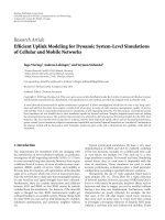
Figure 2: Pixel remapping.
(PE). This is made possible in our approach by remapping
and partitioning the video content by means of pixel subsam-
pling (see Figure 2). Two architectural variations have been
designed using 4 PEs (Figure 3) and 16 PEs, respectively. For
clarity all the equations, diagrams, and examples provided
concentrate on the 4
× PE architecture only, but can be easily
extended.
2.3. Proposed ME architecture
Early termination of the SAD calculation is based on the
premise that if the current block match has an intermedi-
ate SAD value exceeding that of the minimum SAD found
so far, early termination is possible. In hardware implemen-
tations usage of this technique is rare [16], since the serial
type processing required for SAD cancellation is not suited
to SA architectures. Our proposed design uses SAD cancel-
lation while avoiding the low throughput issues of a fully
serial solution by employing pixel subsampling/remapping.
In comparison to [16], which also implements early termi-
nation in a 2D SA architecture, the granularity of the SAD
cancellation is far greater in our design. This will ultimately
lead to greater dynamic power savings. While our approach
employs 4 or 16 PEs, the 2D SA architecture uses 256 PEs in
[16], hence roughly 64 to 16 times area savings are achieved
with our architectures, respectively. As in any trade-off, these
significant power and area savings are possible in our archi-
tectures at the expense of lower throughput (see Section 2.4).
However, apart from the power-aware trade-off we propose
with our architecture, another advantage is the fact that they
can be reconfigured at run time to deal with variable block
size, which is not the case for the SA architectures.
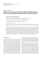
In order to carry out the early exit in parallel hardware,
the SAD cancellation mechanism has to encompass both the
4 EURASIP Journal on Embedded Systems
TOT AL DACC REG
TOT AL
MIN SAD REG
Update stage
C
in
MUX
MUX
BSAD
REG 0
BSAD
REG 1
BSAD
REG 2
BSAD
REG 3
DMUX
PREV
DACC
REG 0
PREV
DACC
REG 1
PREV
DACC
REG 2
PREV
DACC
REG 3
1’s complement
BM PE 0 BM PE 1 BM PE 2 BM PE 3
rb
0
cb
0
rb
1
cb
1
rb
2
cb
2
rb
3
cb
3
Figure 3: 4 × PE architecture.
block (B) and macroblock (MB) levels. The proposed solu-
tion is to employ block-level parallelism in the SAD formula
(see (4)) and then transform the equation from calculating
an absolute value (6) to calculating a relative value to the cur-
rent min SAD (7),
SAD
MB
c
,MB
r
=
16
i=1
16
j=1
MB
c
(i, j) − MB
r
(i, j)
=
3
k=0
8
i=1
8
j=1
B
c
k
(i, j)−B
r
k
(i, j)
=
3
k=0
BSAD
k
,
(4)
min SAD
=
3
k=0
min BSAD
k
,(5)
curr SAD
MB
c
,MB
r
=
3
k=0
curr BSAD
k
,(6)
rel SAD
MB
c
,MB
r
=
min SAD − curr SAD
MB
c
,MB
r
=
3
k=0
min BSAD
k
− curr BSAD
k
.
(7)
Equation (5) gives the min SAD’s formula, calculated
for the best match with (4). One should notice that the
min BSAD
k
values are not the minimum SAD values for the
respective blocks. However, together the y give the minimum
SAD at MB-level. Min SAD and min BSAD
k
are constant
throughout the subsequent block matches (in (7)) until they
are replaced by next best matches’ SAD values. Analysing (7)
the following observations can be made. First, from a hard-
ware point of view, the SAD cancellation comparison is im-
plemented by de-accumulating instead of accumulating the
absolute differences. Thus two operations (accumulation and
comparison) can be implemented with only one operation
(de-accumulation). Hence, anytime all block-level rel BSAD
k
values are negative, it is obvious that a SAD cancellation con-
dition has been met and one should proceed to the next
match. Statistically, the occurrence of the early SAD can-
cellation is frequent (test sequence dependent) and there-
fore the calculation of the overall rel SAD value is seldom
needed. Thus, in the proposed architecture the rel SAD up-
date is carried out only if no cancellation occurred. Thus,
if by the end of a match the SAD cancellation has not been
met, only then rel SAD has to be calculated to see if globally
(at MB le vel) the rel BSAD
k
values give a better match (i.e.,
a negative rel SAD is obtained). During the update stage, if
the rel SAD is negative, then no other update/correction is
needed. However, if it is a better match, then the min SAD
and min BSAD
k
values have also to be updated. The new best
match min BSAD
k
values have also to be updated at block-
level for the current and next matches. This is the function
of the update stage. Second, it is clear intuitively from (7)
that the smaller the min BSAD
k
values are, the greater the
probability for early SAD cancellation is. Thus, the quicker
the SAD algorithm converges toward the best matches (i.e.,
smaller min BSAD
k
), the more effective the SAD cancella-
tion mechanism is at saving redundant operations. If SAD
cancellation does not occur, all operations must be carried
out. This implies that investigations should focus on motion
prediction techniques and snail-type search strategies (e.g.,
circular, diamond) which start searching from the position
that is most likely to be the best match, obtaining the small-
est min BSAD
k
values from earlier steps. Third, there is a
higher probability (proved experimentally by this work) that
the block-level rel BSAD
k
values become negative at the same
time before the end of the match, if the blocks (B) are similar
lower-resolution versions of the macroblock (MB). This can
be achieved by remapping the video content as in Figure 2,
Andrew Kinane et al. 5
htbp
Sign bit
used for SAD
cancellation
15 Deaccumulator
DACC
REG
k
1
15
C
in
2’s complement
15
15
load
prev dacc val
load
local SAD val
MUX and C
in control
4:1
66
15 15
PE control
logic
‘1’ ‘1’
prev
dacc val
local
SAD val
9
1
1’s complement
Sign bit
C
in
= 1
11
8
‘1’‘0’
8
cb
k
rb
k
1’s complement
absolute
difference
Figure 4: Texture PE.
where the video frame is subsampled and partitioned in 4
subframes with similar content. Thus the ME memory (both
for current block and search area) is organised in four banks
that are accessed in parallel.
Figure 4 depicts a detailed view of a block-matching
(BM) processing element (PE) proposed here. A SAD cal-
culation implies a subtraction, an absolute, and an accu-
mulation operation. Since only values relatives to the cur-
rent min SAD and min BSAD
k
values are calculated, a de-
accumulation function is used instead. The absolute differ-
ence is de-accumulated from the DACC
REG
k
register (de-
accumulator).
At each moment, the DACC
REG
k
stores the appropri-
ate rel BSAD
k
value and signals immediately with its sign
bit if it becomes negative. The initial value stored in the
DACC
REG
k
at the beginning of each match is the cor-
responding min BSAD
k
value and is brought through the
local
SAD val inputs. Whenever all the DACC REG
k
de-
accumulate become negative they signal a SAD cancellation
condition and the update stage is kept idle.
The update stage is carried out in parallel with the next
match’s operations executed in the block-level datapaths be-
cause it takes at most 11 cycles. Therefore, a pure sequential
scheduling of the update stage operations is implemented in
the update stage hardware (Figure 3). There are three pos-
sible update stage execution scenarios: first, when it is idle
most of the time, second, when the update is launched at
the end of a match, but after 5 steps the gl obal rel SAD turns
out to be negative and no update is deemed necessary (see
Figure 5(a)), third, when after 5 steps rel SAD is positive (see
Figure 5(b)). In the latter case, the min SAD and min BSAD
k
values, stored, respectively , in TO T MIN SAD REG and
BSAD
REG
k
, are updated. Also, the rel BSAD
k
correc-
tions, stored beforehand in the PREV
DACC REG
k
reg-
isters,havetobemadetothePEs’DACC
REG
k
regis-
ters. The correction operation involves a subtraction of the
PREV
DACC REG
k
values (inverters provided in Figure 3
to obtain 2’s complement) from the DACC
REG
k
registers
through the prev
dacc val inputs of the BM PEs. There is an
extra cycle added for the correction operation, when the PE
halts the nor m al de-accumulation function. These correc-
tions change the min SAD and min BSAD
k
values, thus the
PEs should have started with in the new match less than 11
cycles ago. One should also note that if a new SAD cancella-
tion occurs and a new match is skipped, this does not affect
the update stage’s operations. That is due to the fact that a
match skip means that the resulting curr SAD value was get-
ting larger than the current min SAD which can only be up-
dated with a smaller v alue. Thus, the match skip would have
happened even if the min SAD value had been updated al-
ready before the start of the current skipped match.
2.4. Experimental results
A comparison in terms of operations and cycles between our
adaptive architecture (with a circular search, a 16
× 16 MB
and a search window of
±7 pels) and two SA architectures (a
typical 1D SA architecture and a 2D SA architecture [16]) is
carried out in this sec tion. Results are presented for a variety
of MPEG QCIF test sequences. Table 1 shows that our early
termination architecture outperforms a typical 1D SA archi-
tecture. The 4
× PE succeeds in cancelling the largest number
of SAD operations (70% average reduction for the sequences
listed in Ta bl e 1), but at the price of a longer execution time
(i.e., larger number of cycles) for videos that exhibit high lev-
els of motion (e.g., the MPEG Foreman test sequence). The
16
× PE outperforms the 1D SA both for the number of SAD
operations and for the total number of cycles (i.e., execution
time). In comparison with the 4
×PE architecture, the 16×PE
architecture is faster but removes less redundant SAD op-
erations. Thus, choosing between 4
× PE and 16 × PE is a
trade-off between processing speed and power savings. With
either architecture, to cover scenarios where there is below
average early termination (e.g., Foreman sequence), the op-
erating clock frequency is set to a frequency which includes a
margin that provides adequate throughput for natural video
sequences.
In comparison with the 2D SA architecture proposed
in [16 ], our architecture outperforms in terms of area and
switching (SAD operations) activity. A pip elined 2D SA ar-
chitecture as the one presented in [16] executes the 1551 mil-
lion SAD operations in approximately 13 million clock cy-
cles. The architecture in [16] pays the price of disabling the
switching for up to 45% of the SAD operations by employ-
ing extra logic (requiring at least 66 adders/subtracters), to
6 EURASIP Journal on Embedded Systems
Block-level
operations
Update stage
operations
Idle Idle Idle Idle
No update
5cycles
Idle Idle Idle
64-cycle
BMs
BM-skip
(a) Update stage launched but no update
Block-level
operations
Update stage
operations
Idle Idle Idle Idle
Update
11 cycles
Idle Idle
64-cycle
BMs
BM-skip BM-skip
New BM
+1 cycle
(b) Update stage launched, BM-skip, and update executed
Figure 5: Parallel update stage scenarios.
Table 1: ME architecture comparison for QCIF test sequences.
SAD operations (millions) Cycles (millions)
1D SA 4 × PE % 16 × PE % 1D SA 4 × PE%16× PE %
Akiyo 1551 M 130 M 8% 357 M 23% 103 M 33 M 31% 22 M 21%
Coastguard
1551 M 443 M 28% 665 M 43% 103 M 110 M 106% 42 M 40%
Foreman
1551 M 509 M 33% 730 M 47% 103 M 127 M 123% 47 M 45%
M&d
1551 M 359 M 23% 603 M 39% 103 M 90 M 86% 40 M 39%
Table tennis
1551 M 408 M 26% 641 M 41% 103 M 102 M 98% 45 M 43%
carry out a conserv ative SAD estimation. With 4 PEs and
16 PEs, respectively, our architectures are approximately 64
and 16 times smaller (excluding the conservative SAD esti-
mation log ic). In terms of switching, special latching logic is
employed to block up to 45% of the SAD operation switch-
ing. This is on average less than the number of SAD opera-
tions cancelled by our architectures. In terms of throughput,
our architectures are up to 10 times slower than the 2D SA
architecture proposed in [ 16], but for slow motion test se-
quences (e.g., akiyo), the performance is very much compa-
rable. Hence, we claim that the trade-off offered by our archi-
tectures is more suitable to power-sensitive mobile devices.
The ME 4
× PE design was captured using Verilog HDL
and synthesised using Synopsys Design Compiler, targeting
a TSMC 90 nm library characterised for low power. The re-
sultant area was 7.5 K gates, with a maximum possible oper-
ating frequency f
max
of 700 MHz. The average power con-
sumption for a range of video test sequences is 1.2 mW
(@100 MHz, 1.2 V, 25
◦
C). Using the normalisations pre-
sented in Section 1.2.2,itisclearfromTable 2 that the nor-
malised power (P
) and energy (E
) of Takahashi et al. [17]
and Nakayama et al. [15] are comparable to the proposed
architecture. The fact that the normalised energies of all
three approaches are comparable is interesting, since both
Takahashi and Nakayama use fast heuristic search strategies,
whereas the proposed architecture uses a fast-exhaustive ap-
proach based on SAD cancellation. Nakayama have a better
normalised EDP but they use only the top four bits of each
pixel when computing the SAD, at the cost of image quality.
The fast-exhaustive approach has benefits such as more reg-
ular memory access patterns and smaller prediction residuals
(betterPSNR).Thelatterbenefithaspowerconsequencesfor
the subsequent transform coding , quantisation and entropy
coding of the prediction residual.
3. BINARY MOTION ESTIMATION
3.1. Algorithm
Similar to texture pixel encoding, if a binary alpha block
(BAB) belongs to a MPEG-4 inter video object plane (P-
VOP), temporal redundancy can be exploited through the
use of motion estimation. However, it is generally accepted
that motion estimation for shape is the most computation-
ally intensive block within binary shape encoding [18]. Be-
cause of this computational complexity hot spot, we leverage
and extend our work on the ME core to carry out BME pro-
cessing in a power-efficient manner.
The motion estimation for shape process begins with the
generation of a motion vector predictor for shape (MVPS)
[19]. The predicted motion compensated BAB is retrieved
and compared against the current BAB. If the error between
each 4
× 4 sub block of the predicted BAB and the current
BAB is l ess than a predefined threshold, the motion vector
predictor can be used directly [19]. Otherwise an accurate
motion vector for shape (MVS) is required. MVS is a conven-
tional BME process. Any search strategy can be used and typ-
ically a search window size of
±16 pixels around the MVPS
BAB is employed.
3.2. Prior art review
Yu et al. outline a software implementation for motion es-
timation for shape , which uses a number of intermediate
thresholds in a heuristic search str ategy to reduce the compu-
tational complexity [20]. We do not consider this approach
viable for a hardware implementation due to the irregular
memory addressing, in addition to providing limited scope
for exploiting parallelism.
Andrew Kinane et al. 7
Table 2: ME synthesis results and benchmarking.
Architecture
Tec h Cycle count
Gates PGCC
f Power P
E
EDP
(μm) Max Min Average (MHz) (mW) (mW) (nJ) (fJs)
Takahashi et al. [17] 0.25 32 768 n/a 16 384 n/a n/a 60 2.8 0.3 81 22 401
Nakayama et al. [15]
0.18 n/a n/a 300 n/a n/a 250 9.0 1.8 40 889
Proposed
0.09 16 384 574 3618 7577 2.74 × 10
7
100 1.2 1.2 43 1508
Boundary mask methods can be employed in a prepro-
cessing manner to reduce the number of search positions
[21, 22]. The mask generation method proposed by Panu-
sopone and Chen, however, is computational intensive due
to the block loop process [21]. Tsai and Chen use a more effi-
cient approach [22] and present a proposed hardware archi-
tecture. In addition Tsai et al. use heuristics to further reduce
the search positions. Chang et al. use a 1D systolic array ar-
chitecture coupled with a full search stra tegy for the BME im-
plementation [18]. Improving memory access performance
is a common optimisation in MPEG-4 binary shape encoders
[23, 24]. Lee et al. suggest a run length coding scheme to
minimise on-chip data transfer and reduce memory require-
ments, however the run length codes stil l need to be decoded
prior to BME [24].
Our proposed solution leverages our ME SAD cancella-
tion architecture and extends this by avoiding unnecessary
operations by exploiting redundancies in the binary shape
information. This is in contrast to a SA approach, where un-
necessary calculations are unavoidable due to the data flow in
the systolic struc ture. Unlike the approach of Tsai and Chen,
we use an exhaustive search to guar antee finding the best
block match w ithin the search range [22].
3.3. Proposed BME architecture
When using binary-valued data the ME SAD opera tion sim-
plifies to the for m given in (8), where B
cur
is the BAB under
consideration in the current binary alpha plane (BAP) and
B
ref
is the BAB at the current search location in the reference
BAP,
SAD
B
cur
, B
ref
=
i=16
i=1
j
=16
j=1
B
cur
(i, j) ⊗ B
ref
(i, j). (8)
In previous BME research, no attempts have been made to
optimise the SAD PE datapath. However, the unique char-
acteristics of binary data mean further redundancies can be
exploited to reduce datapath switching activity. It can be seen
from (8) that there are unnecessary memory accesses and op-
erations w hen both B
cur
and B
ref
pixels have the same value,
since the XOR will give a zero result. To minimise this effect,
we propose reformulating the conventional SAD equation.
ThefollowingpropertiescanbeobservedfromFigure 6(a):
TOT AL
cur
= COMMON + UNIQUE
cur
,
TOT AL
ref
= COMMON + UNIQUE
ref
,
(9)
where
(a) TOTAL
cur
is the total number of white pixels in the
current BAB.
(b) TOTAL
ref
is the total number of white pixels in the ref-
erence BAB.
(c) COMMON is the number of white pixels that are com-
mon in both the reference BAB and the current BAB.
(d) UNIQUE
cur
is the number of white pixels in the cur-
rent BAB but not in the reference BAB.
(e) UNIQUE
ref
is the number of white pixels in the refer-
ence block but not in the current BAB.
It is also clear from Figure 6(a), that the SAD value be-
tween the current and reference BAB can be represented as
SAD
= UNIQUE
cur
+UNIQUE
ref
. (10)
Using these identifies, it follows that
SAD
= TOTAL
ref
− TOT AL
cur
+2× UNIQUE
cur
. (11)
Equation (11) can be intuitively understood as TOTAL
ref
−
TOT AL
cur
being a conservative estimate of the SAD value,
whilst 2
× UNIQUE
cur
is an adjustment to the conservative
SAD estimate to give the correct final SAD value. The reason
equation (11) is beneficial is because the following.
(a) TOTAL
cur
is calculated only once per search.
(b) TOTAL
ref
can be updated in 1 clock cycle, after initial
calculation, provided a circular search is used.
(c) Incremental addition of UNIQUE
cur
allows early ter-
mination if the current minimum SAD is exceeded.
(d) Whilst it is not possible to know UNIQUE
cur
in ad-
vance of a block match, run length coding can be used
to encode the position of the white pixels in the current
BAB, thus minimising access to irrelevant data.
Run length codes (RLC) are generated in parallel with the
first block match of the search window, an example of typi-
cal RLC is illustrated in Figure 7. It is possible to do the run
length encoding during the first match, because early termi-
nation of the SAD calculation is not possible at this stage,
since a minimum SAD has not been found. The first match
8 EURASIP Journal on Embedded Systems
Reference BAB Current BA B
TOT AL
ref
TOT AL
cur
UNIQUE
ref
UNIQUE
cur
COMMON
+
+
(a) Reform BC
dacc reg
Sign cha nge
(early termination)
DACC
REG
c
in
+
0
PE
ctrl
prev
dacc val
local
minsad
TOT AL
cur
TOT AL
ref
cur pixel ref pixel
X2
(b) BME PE
Figure 6: Bit count reformulation and BME PE.
Current macroblock
Location of white pixels given by
RL1 (1, 1)
RL2 (15, 3)
RL3 (13, 4)
RL4 (12, 5)
RL5 (11, 32)
RL6 (160, 0)
Location of black pixels given by
RL0 (0, 1)
RL1 (1, 15)
RL3 (3, 13)
RL4 (4, 12)
RL5 (5, 11)
RL6 (32, 160)
Figure 7: Regular and inverse RLC pixel addressing.
always takes N × N (where N is the block size) cycles to com-
plete and this provides ample time for the run length encod-
ing process to operate in parallel. After the RLC encoding,
the logic can be powered down until the next current block
is processed.
In situations where there are fewer black pixels than white
pixels in the current MB or where TOTAL
cur
is greater than
TOT AL
ref
,(12) is used instead of (11). Since run length cod-
ing the reference BAB is not feasible, UNIQUE
ref
can be gen-
erated by examining the black pixels in the current BAB. The
location of the black pixels can be automatically derived from
the RLC for the white pixels (see Figure 7). Thus, by reusing
the RLC associated with the white pixels, additional memory
is not required and furthermore the same SAD datapath can
be reused with minimal additional logic,
SAD
= TOT AL
cur
− TOT AL
ref
+2× UNIQUE
ref
. (12)
Figure 6(b) shows a detailed view of the BME SAD PE.
At the first clock cycle, the minimum SAD encountered
so far is loaded into DACC
REG. During the next cycle
TOT AL
cur
/TOTAL
ref
is added to DACC REG (depending
if TOTAL
ref
[MSB]is0or1,respectively,orifTOTAL
ref
is
larger than TOTAL
cur
). On the next clock cycle, DACC REG
is de-accumulated by TOTAL
ref
/TOTAL
cur
again depending
on whether TOTAL
ref
[MSB]is0or1,respectively.Ifasign
change occurs at this point, the minimum SAD has already
been exceeded and no further processing is required. If a
sign change has not occurred, the address generation unit re-
trieves the next RLC from memory. This is decoded to give an
X, Y macroblock address. The X, Y address is used to retrieve
the relevant pixel from the reference MB and the current
MB. The pixel values are XORed and the result is left shifted
Andrew Kinane et al. 9
Table 3: BME synthesis results and benchmarking.
Architecture
Tec h Cycle count
Gates PGCC
f Power P
E
EDP
(μm) Max Min Average (MHz) (mW) (mW) (nJ) (fJs)
Natarajan et al. [25] n/a 1039 1039 1039 n/a n/a n/a n/a n/a n/a n/a
Lee et al. [23]
n/a 1056 1056 1056 n/a n/a n/a n/a n/a n/a n/a
Chang et al. [18]
0.35 1039 1039 1039 9666 1.00 × 10
7
40 n/a n/a n/a n/a
Proposed
0.09 65 535 2112 6554 10 117 6.63 × 10
7
100 1.22 1.22 80 5240
by one place and then subtracted from the DACC REG. If
a sign change occurs, early termination is possible. If not
the remaining pixels in the current run length code are pro-
cessed. If the SAD calculation is not cancelled, subsequent
run length codes for the current MB are fetched from mem-
ory and the processing repeats.
When a SAD has been calculated or terminated early, the
address generation unit moves the reference block to a new
position. Provided a circular or full search is used, TOTAL
ref
can be updated in one clock cycle. This is done by subtract-
ing the previous row or column (depending on search win-
dow movement) from TOTAL
ref
and adding the new row or
column, this is done via a simple adder tree.
In order to exploit SAD cancellation, an intermediate
partial SAD must be generated. This requires SAD calcula-
tion to proceed in a sequential manner, however this reduces
encoding throughput and is not desirable for real time ap-
plications. To increase throughput parallelism must be ex-
ploited. Therefore, we leverage our ME approach and repar-
tition the BAB into four 8
× 8 blocks by using a simple pixel
subsampling technique. Four PEs, each operating on one
8
× 8 block, generate four partial SAD values. The control
logic uses these partially accumulated SAD values to make an
overall SAD cancellation decision. If SAD cancellation does
not occur and all alpha pixels in the block a re processed, the
update stage is evoked. The update logic is identical to the
ME unit. Similar to the ME architecture, 16 PE can also be
used, albeit at the expense of reduced cancellation.
3.4. Experimental results
Table 3 summarises the synthesis results for the proposed
BME architecture using 4 PE. Synthesising the design
with Synopsys Design Compiler targeting TSMC 0.09 μm
TCBN90LP technolog y yields a gate count of 10 117 and a
maximum theoretical operating frequency f
max
of 700 MHz.
Unlike the constant throughput SA approaches, the process-
ing latency to generate one set of motion vectors for the pro-
posed architecture is data dependant. The worst and best
case processing latencies are 65 535 and 3133 clock cycles,
respectively. Similar to our ME architecture, the clock fre-
quency includes a margin to cover below average early ter-
mination. As reported in our prior work [26], we achieve
on average 90% early termination using common test se-
quences. Consequently this figure is used in the calculation
of the PGCC (6.63
× 10
7
). BME benchmarking is difficult
due to a lack of information in prior art, this includes BME
architectures used in MPEG-4 binary shape coding and BME
architectures used in low complexity approaches for texture
ME [18, 22, 23, 25, 27].
The SA BME architecture proposed by Natarajan et al., is
leveraged in the designs proposed by Chang et al. and Lee et
al. Consequently similar cycle counts can be observed in each
implementation [18, 23, 25]. The average cycle counts (6553
cycles) for our architecture is longer than the architecture
proposed by Chang et al. [18], this is due to our architectural
level design decision to trade off throughput for reduced SAD
operations and consequently reduced power consumption.
As a consequence of the longer latency, the PGCC for our
proposed architecture is inferior to that of the architecture
proposed by Chang et al. [18]. However, the PGCC metr ic
does not take into account the nonuniform switching in our
proposed design. For example, after the first block match the
run length encoder associated with each PE is not active, in
addition the linear pixel addressing for the first block match
is replaced by the run length decoded pixel scheme for sub-
sequent BM within the search window. The power, energy,
and EDP all take account of the nonuniform data-dependant
processing, however, benchmarking against prior art using
these metrics is not possible due to a lack of information in
the literature.
4. SHAPE ADAPTIVE DCT
4.1. Algorithm
When encoding texture, an MPEG-4 codec divides each rect-
angular video frame into an array of nonoverlapping 8
× 8
texture blocks and processes these sequentially using the SA-
DCT [28]. For blocks that are located entirely inside the VOP,
the SA-DCT behaves identically to the 8
× 8 DCT. Any blocks
located entirely outside the VOP are skipped to save need-
less processing. Blocks that lie on the VOP boundary (e.g.,
Figure 8) are encoded depending on their shape and only the
opaque pixels within the boundary blocks are actually coded.
The additional factors that make the SA-DCT more com-
putationally complex with respect to the 8
× 8DCTarevec-
tor shape parsing, data alignment, and the need for a vari-
able N-point 1D DCT transform. The SA-DCT is less regular
compared to the 8
× 8 block-based DCT since its processing
decisions are entirely dependent on the shape information
associated with each individual block.
10 EURASIP Journal on Embedded Systems
VOP boundary
pixel block
Example
alpha block
VOP
Non-VOP
Figure 8: Example VOP boundary block.
4.2. Prior art review
Le and Glesner have proposed two SA-DCT architectures—
a recursive structure and a feed-forward structure [29]. The
authors favour the feed-forward architecture and this has a
hardware cost of 11 adders and 5 multipliers, with a cycle
latency of N +2foranN-point DCT. However, neither of
the architectures address the horizontal packing required to
identify the lengths of the horizontal transforms and have
the area and power disadvantage of using expensive hardware
multipliers.
Tseng et al. propose a reconfigurable pipeline that is dy-
namically configured according to the shape information
[30]. The architecture is hampered by the fact that the en-
tire 8
× 8 shape information must be parsed to configure the
datapath “contexts” prior to texture processing.
Chen et al. developed a programmable datapath that
avoids multipliers by using canonic signed digit (CSD)
adder-based distributed arithmetic [31, 32]. The hardware
cost of the datapath is 3100 gates requiring only a s ingle
adder, which is reused recursively when computing multiply-
accumulates. This small area is traded-off against cycle
latency—1904 in the worst case scenario. The authors do
not comment on the perceptual performance degradation or
otherwise caused by approximating odd length DCTs with
even DCTs.
Lee et al. considered the packing functionality require-
ment and developed a resource shared datapath using adders
and multipliers coupled with an autoaligning transpose
memory [33]. The datapath is implemented using 4 multipli-
ers and 11 adders. The worst case computation cycle latency
is 11 clock cycles for an 8-point 1D DCT. This is the most ad-
vanced implementation, but the critical path caused by the
multipliers in this architecture limits the maximum operat-
ing frequency and has negative power consumption conse-
quences.
4.3. Proposed SA-DCT architecture
The SA-DCT architecture proposed in this paper tackles the
deficiencies of the prior art by employing a reconfiguring
adder-only-based distributed arithmetic structure. Multipli-
ers are avoided for area and power reasons [32]. The top-
level SA-DCT architecture is shown in Figure 9, comprising
of the transpose memory (TRAM) and datapath with their
associated control logic. For all modules, local clock gating
is employed based on the computation being car ried out to
avoid wasted power .
It is estimated that an m-bit Booth multiplier costs ap-
proximately 18–20 times the area of an m-bit ripple carry
adder [32]. In terms of power consumption, the ratio of
multiplier power versus adder power is slightly smaller than
area ratio since the transition probabilities for the individual
nodes are different for both circuits. For these reasons, the
architecture presented here is implemented with adders only.
4.3.1. Memory and control architecture
The primary feature of the memory and addressing mod-
ules in Figure 9 is that they avoid redundant register switch-
ing and latency when addressing data and storing interme-
diate values by manipulating the shape information. The ad-
dressing and control logic (ACL) parses shape and pixel data
from an external memory and routes the data to the variable
N-point 1D DCT datapath for processing in a column-wise
fashion. The intermediate coefficients after the horizontal
processing are stored in the TRAM. The ACL then reads each
vertical data vector from this TRAM for horizontal transfor-
mation by the datapath.
The ACL has a set of pipelined data registers (BUFFER
and CURRENT) that are used to buffer up data before rout-
ing to the variable N-point DCT datapath. There are also
a set of interleaved modulo-8 counters (N
buff A r and
N
buff B r). Each counter either stores the number of VOP
pels in BUFFER or in CURRENT, depending on a selec-
tion signal. This pipelined/interleaved structure means that
as soon as the data in CURRENT has completed processing,
the next data vector has been loaded into BUFFER with its
shape parsed. It is immediately ready for processing, thereby
maximising throughput and minimising overall latency.
Data is read serially from the external data bus if in ver-
tical mode or from the local TRAM if in horizontal mode. In
vertical mode, when valid VOP pixel data is present on the
input data bus, it is stored in location BUFFER[N buff i r]
in the next clock cycle (where i
∈{A, B} depends on the
interleaved selection signal). The 4-bit register N
buff i r is
also incremented by 1 in the same cycle, which represents
the number of VOP pels in BUFFER (i.e., the vertical N
value). In this way vertical packing is done without redun-
dant shift cycles and u nnecessary power consumption. In
horizontal mode, a simple FSM is used to address the TRAM.
It using the N values already parsed in the vertical process
Andrew Kinane et al. 11
Datapath
control
logic
PPST
Multiplexed
weight
generation
module
Even/odd
decomp.
Addressing
control logic
Variab le N-point 1D-DCT datapath
Halt
Vali d
Alpha [7:0]
Data [8:0]
SA-DCT
Transp o se
RAM
Final
horz
Valid [1:0]
F
k[11:0]
Figure 9: Top-level SA-DCT architecture.
Signal valid forms
a logical AND with
register write enables for
appropriate clock gating
valid
even/odd
N
f (7)
f (6)
f (5)
f (4)
f (3)
f (2)
f (1)
f (0)
GND
f (4)
GND
f (3)
f (5)
GND
f (2)
f (6)
GND
f (1)
f (7)
EOD
1
01
01
0
10
+
+
+
+
c
in
c
in
c
in
c
in
s(0)
s(1)
s(2)
s(3)
d(0)
d(1)
d(2)
d(3)
D
L
Q
Q
SET
CLR
D
L
Q
Q
SET
CLR
D
L
Q
Q
SET
CLR
D
L
Q
Q
SET
CLR
D
L
Q
Q
SET
CLR
D
L
Q
Q
SET
CLR
D
L
Q
Q
SET
CLR
D
L
Q
Q
SET
CLR
even/odd
Vec tor
selection
Primary adders
Secondary
adders
x3 x2 x1 x0
2:1 2:1 2:1 2:1
+
+
+
+
+
+
x0+x1
x2+x3
x0+x2
x0+x3
x1+x2
x1+x3
x01x23x02x03x12x13
+
+
+
+
+
MWGM
valid
x01 + x23
x01 + x2
x01 + x3
x02 + x3
x12 + x3
x01x23
x01x2
x01x3
x02x3
x12x3
Weight MUX routing
k
N
36 : 1
36 : 1
36 : 1
36 : 1
36 : 1
36 : 1
36 : 1
36 : 1
36 : 1
36 : 1
36 : 1
36 : 1
36 : 1
W
−12
W
−11
W
−10
W
−9
W
−8
W
−7
W
−6
W
−5
W
−4
W
−3
W
−2
W
−1
W
0
D
L
Q
Q
SET
CLR
D
L
Q
Q
SET
CLR
D
L
Q
Q
SET
CLR
D
L
Q
Q
SET
CLR
D
L
Q
Q
SET
CLR
D
L
Q
Q
SET
CLR
D
L
Q
Q
SET
CLR
D
L
Q
Q
SET
CLR
D
L
Q
Q
SET
CLR
D
L
Q
Q
SET
CLR
D
L
Q
Q
SET
CLR
D
L
Q
Q
SET
CLR
D
L
Q
Q
SET
CLR
W
−12
W
−11
W
−10
W
−9
W
−8
W
−7
W
−6
W
−5
W
−4
W
−3
W
−2
W
−1
W
0
(4; 2) (4; 2) (4; 2)
(3 : 2) (4; 2)
(4; 2)
+
Round
PPST
Valid
Ver t/ h or z
F(k)
D
L
Q
Q
SET
CLR
Variable N-point DCT processor
Figure 10: Variable N-point 1D DCT processor.
to minimise the number of accesses. The same scheme en-
sures horizontal packing is done without redundant shift cy-
cles.
The TRAM is a 64-word
× 15-bit RAM that stores the co-
efficients produced by the datapath when computing the ver-
tical1Dtransforms.Thesecoefficients are then read by the
ACL in a transposed fashion and horizontally transformed
by the datapath yielding the final SA-DCT coefficients. When
storing data, the coefficient index k is manipulated to store
the value at address 8
× k +NRAM[k]. Then NRAM[k]is
incremented by 1. In this way, when an entire block has
been vertically transformed, the TRAM has the resultant data
stored in a horizontally packed manner with the horizontal N
values ready in NRAM immediately w ithout shifting. These
N values are used by the ACL to minimise TRAM reads for
the horizontal transforms.
4.3.2. Datapath architecture
The variable N-point 1D DCT module is shown in Figure 10,
which computes all N coefficients serially starting with F[N
−
1] down to F[0]. This is achieved using even/odd decomposi-
tion (EOD), followed by adder-based distributed arithmetic
using a multiplexed weight generation module (MWGM)
and a partial product summation tree (PPST). A serial coef-
ficient computation scheme was chosen because of the adap-
tive nature of the computations and the shape parsing logic
is simpler this way.
EOD exploits the inherent symmetries in the SA-DCT
cosine basis functions to reduce the complexity of the subse-
quent MWGM computation. The EOD module (Figure 10)
decomposes the input vector and reuses the same adders for
both even and odd k. This adder reuse requires MUXs but
12 EURASIP Journal on Embedded Systems
Table 4: SA-DCT synthesis results and benchmarking.
Architecture
Tec h Cycle count
+ ∗ Gates PGCC
f Power P
E
EDP
(μm) Max Min (MHz) (mW) (mW) (nJ) (fJs)
Le and Glesner [29] ♦ 0.7 10 3 11 5 n/a n/a 40 n/a n/a n/a n/a
Tseng et al. [ 30]
0.35 n/a n/a n/a n/a n/a n/a 66 180.00 4.33 n/a n/a
Chen et al. [32]
♦
0.35
124 14 1 0 3157 3.9 × 10
5
83
n/a n/a n/a n/a
1984 14 n/a n/a 5775 3.9 × 10
7
12.44 0.55 12.58 289
Lee et al. [33] ♦
0.35 11 3 11 4 17 341 1.9 × 10
5
66.7 n/a n/a n/a n/a
Proposed
approach
♦
0.09
10 3 27 0 12016 1.2 × 10
5
11
n/a n/a n/a n/a
142 79 31 0 25 583 3.6 × 10
6
0.36 0.36 6.18 60
Key: ♦ ⇒ datapath only, ⇒ datapath and memory.
the savings in terms of adders offsets this and results in an
overall area improvement with only a slight increase in crit-
ical path delay. Register clocking of s and d is controlled so
that switching only occurs when necessary.
The dot product of the (decomposed) data vector with
the appropriate N-point DCT basis vector yielding SA-DCT
coefficient k is computed using a reconfiguring adder-based
distributed arithmetic structure (the MWGM) followed by a
PPST as shown in Figure 10. Using dedicated units for dif-
ferent
{k, N} combinations (where at most only one will be
active at any instant) is avoided by employing a reconfigur-
ing multiplexing structure based on
{k, N} that reuses single
resources. Experimental results have shown that for a range
of video test sequences, 13 distributed binary weights are
needed to adequately satisfy reconstructed image quality re-
quirements [34]. The adder requirement (11 in total) for the
13-weight MWGM has been derived using a recursive itera-
tive matching algorithm [35].
The datapath of the MWGM is configured to compute
the distributed weights for N-point DCT coefficient k using
the 6-bit vector
{k, N} as shown in Figure 10. Even though
0
≤ N ≤ 8, the case of N = 0 is redundant so the range
1
≤ N ≤ 8 can be represented using three bits (range 0 ≤ k ≤
N − 1 also requires three bits). Even though the select signal
is 6 bits wide, only 36 cases are valid since the 28 cases where
k
≥ N do not make sense so the MUX logic complexity is
reduced. For each of the weights, there is a certain degree of
equivalence between subsets of the 36 valid cases which again
decreases the MUX complexity. Signal
even/odd (equivalent
to the LSB of k) selects the e ven or odd decomposed data
vector and the selected vector (signals x0, x1, x2, and x3in
Figure 10) drive the 11 adders. Based on
{k, N}, the MUXs
select the appropriate value for each of the 13 weights. There
are 16 possible values (zero and signals x0, x1, , x12x3in
Figure 10) although each weight only chooses from a subset
of these possibilities. The weights are then combined by the
PPST to produce coefficient F(k).
Again, power consumption issues have been considered
by providing a valid signal that permits the data in the weight
registers to only switch when the control logic flags it neces-
sary. The logic paths have been balanced in the implemen-
tation in the sense that the delay paths from each of the
MWGM input ports to the data input of the weight registers
are as similar as possible. This has been a chieved by design-
ing the adders and multiplexers in a tree stru cture as shown
in Figure 10, reducing the probability of net glitching when
new data is presented at the input ports.
The use of adder-based distributed arithmetic necessi-
tates a PPST to combine the weights together to form the
final coefficient as shown in Figure 10. Since it is a potential
critical path, a carry-save Wallace tree structure using (3 : 2)
counters and (4 : 2) compressors has been used to post-
pone carry propagation until the final ripple carry addition.
The weighted nature of the inputs means that the sign ex-
tension can be manipulated to reduce the circuit complexity
of the high order compressors [36]. Vertical coefficients are
rounded to 11. f fixed-point bits (11 bits for integer and f
bits for fractional) and our experiments show that f
= 4rep-
resents a good trade-off between area and performance. This
implies that each word in the TRAM is 15 bits wide. Hor-
izontal coefficients are rounded to 12.0 bits and are routed
directly to the module outputs.
4.4. Experimental results
Table 4 summarises the synthesis results for the proposed
SA-DCT architecture and the normalised power and energy
metrics to facilitate a comparison with prior art. Synthe-
sising the design with Synopsys Design Compiler targeting
TSMC 0.09 μm TCBN90LP technology yields a gate count of
25 583 and a maximum theoretical operating frequency f
max
of 556 MHz. The a rea of the variable N-point 1D DCT dat-
apath is 12 016 (excluding TRAM memory and ACL). Both
gate counts are used to facilitate equivalent b enchmarking
with other approaches based on the information available
in the literature. T he results show the proposed design is an
improvement over Lee [33]andoffers a better trade-off in
terms of cycle count versus area compared with Chen [32],
as discussed subsequently. Area and power consuming mul-
tipliers have been eliminated by using only adders—27 in
total—divided between the EOD module (4), the MWGM
(11) and the PPST (12). Using the estimation that a mul-
tiplier is equivalent to about 20 adders in terms of area,
Andrew Kinane et al. 13
the adder count of the proposed architecture (27) compares
favourably with Le [29](5
× 20 + 11 = 111) and Lee [33]
(4
× 20 + 11 = 91). T his is offset by the additional MUX
overhead, but as evidenced by the overall gate count figure of
the proposed architecture, it still yields an improved circuit
area. By including the TRAM (1) and the ACL controller (3),
an additional 4 adders are required by the entire proposed
design. In total, the entire design therefore uses 31 adders and
no multipliers. In terms of area and latency, the PGCC metric
shows that the proposed architecture outperforms the Chen
[32]andLee[33] architectures.
The power consumption figure of 0.36 mW was obtained
by running back-annotated dynamic simulation of the gate
level netlist for various VO sequences and taking an aver-
age (@11 MHz, 1.2 V, 25
◦
C). The simulations were run at
11 MHz since this is the lowest possible operating frequency
that guarantees 30 fps CIF real-time performance, given a
worst case cycle latency per block of 142 cycles. The Syn-
opsys Prime Power tool is used to analyse the annotated
switching information from a VCD file. Only two of the SA-
DCT implementations in the literature quote power con-
sumption figures and the parameters necessary against which
to perform normalised benchmarking: the architectures by
Tseng et al. [30]andChenetal.[32]. The normalised power,
energy, and energy-delay product (EDP) figures are sum-
marised in Table 4. Note that the energy figures quoted in the
table are the normalised energies required to process a single
opaque 8
× 8 block. Results show that the proposed SA-DCT
architecture compares favourably against both the Tseng and
the Chen architectures. The nor malised energy dissipation
and EDP figures are the most crucial in terms of benchmark-
ing, since the energy dissipated corresponds to the amount
of drain on the battery and the lifetime of the device.
5. SHAPE-ADAPTIVE IDCT
5.1. Algorithm
The SA-IDCT reverses the SA-DCT process in the feedback
loop of a video encoder and also in the decoder. The starting
point for the SA-IDCT is a block of coefficients (that have
been computed by the SA-DCT) and a shape/alpha block
corresponding to the pattern into which the reconstructed
pixels will be ar ranged. The SA-IDCT process begins by pars-
ing the 8
× 8 shape block so that the coefficients can be ad-
dressed correctly and the pixels can be reconstructed in the
correct pattern. Based on the row length (0
≤ N ≤ 8), a
1D N-point IDCT for each row of coefficients is calculated.
Subsequently the produced intermediate horizontal results
are realigned to their correct column according to the shape
block and a 1D N-point IDCT for each column is performed.
Finally the reconstructed pixels are realigned vertically to
their original VOP position.
The additional factors that make the SA-IDCT more
computationally complex with respect to the 8
× 8IDCTare
vector shape parsing, data alignment, and the need for a vari-
able N-point 1D IDCT transform. The SA-IDCT is less regu-
lar compared to the 8
×8 block-based IDCT since its process-
ing decisions are entirely dependent on the shape informa-
tion associated with each individual block. Also, peculiarities
of the SA-IDCT algorithm mean that the shape parsing and
data alignment steps are more complicated compared to the
SA-DCT.
5.2. Prior art review
The architecture by Tseng et al. discussed in Section 4.2,
is also capable of computing variable N-point 1D IDCT
[30]. Again, specific details are not given. The realignment
scheme is mentioned but not described apart from stat-
ing that the look-up table outputs reshift the data. Also,
the programmable architecture by Chen et al., discussed in
Section 4.2, is also capable of variable N-point 1D IDCT
[32]. Again, it approximates odd length IDCTs by padding
to the next highest even IDCT, and does not address the SA-
IDCT realignment operations. The SA-IDCT specific archi-
tecture proposed by Hsu et al. has a datapath that uses time-
multiplexed adders and multipliers coupled with an auto-
aligning transpose memory [37]. It is not clear how their SA-
IDCT autoalignment address generation logic operates. The
architecture also employs skipping of all-zero input data to
save unnecessary computation, although again specific de-
tails discussing how this is achieved are omitted. Hsu et al.
admit that the critical path caused by the multipliers in their
SA-IDCT architecture limits the maximum operating fre-
quency and has negative power consumption consequences.
5.3. Proposed SA-IDCT architecture
The SA-IDCT architecture proposed in this paper addresses
the issues outlined by employing a reconfiguring adder-only
structure, similar to the SA-DCT architecture outlined in the
previous section. The datapath computes serially each recon-
structed pixel k (k
= 0, , N − 1) of an N-point 1D IDCT
by reconfiguring the datapath based on the value of k and N.
Local clock gating is employed using k and N to ensure that
redundant switching is avoided for power efficiency. For lo-
cal storage, a TRAM similar to that for the SA-DCT has been
designed whose surrounding control logic ensures that the
SA-IDCT data realignment is computed efficiently without
needless switching or shifting. A pipelined approach allevi-
ates the computational burden of needing to parse the entire
shape 8
× 8 block before the SA-IDCT c an commence.
Due to the additional algorithmic complexity, it is more
difficult to design a unified SA-DCT/SA-IDCT module com-
pared to a unified 8
× 8 DCT/IDCT module. The reasons for
not attempting to do so in the proposed work may be sum-
marised as follows.
(1) A video decoder only requires the SA-IDCT. Since SA-
DCT and SA-IDCT require different addressing logic,
embedding both in the same core will waste area if the
final product is a video decoder application only.
(2) A video encoder needs both SA-DCT and SA-IDCT,
but if real-time constraints are tight, it may be required
to have the SA-DCT and SA-IDCT cores executing in
parallel. If this is the case, it makes sense to have a ded-
14 EURASIP Journal on Embedded Systems
SA-IDCT
Datapath
control
logic
Valid [1:0]
Pel
addr [5:0]
Final
vert
f
k[8:0]
Transp o se
RAM
Even/odd
recomp .
PPST
Multiplexed
weight
generation
module
Addressing
control logic
Variab le N-point 1D-IDCT datapath
Alpha
valid
Alpha [7:0]
Data
valid
Data [11:0]
Rdy
for alpha
Rdy
for data
Data
raddr [5:0]
Figure 11: Top-level SA-IDCT architecture.
1 2 3 4 5 6 7 8 9 10 11 12 13
t
1D IDCT
Parse
Alpha
Buffer Y
Buffer X
H blk0 V blk0 H blk1 V blk1 H blk2 V blk2 H blk3 V blk3 H blk4 V blk4 H blk5 V blk5
pa blk0 pa blk1 pa blk2 pa blk3 pa blk4 pa blk5 pa blk6
blk1 blk3 blk5
blk0 blk2 blk4 blk6
Figure 12: SA-IDCT ACL data processing pipeline.
icated task-optimised core. Admittedly, this has nega-
tive silicon area implications.
(3) Even though the addressing logic for SA-DCT and
SA-IDCT are quite different, the core datapaths that
compute the transforms are very similar. Therefore it
may be viable to design a unified variable N-point
1D DCT/IDCT datapath and have separate dedicated
addressing logic for each. Future work could involve
designing such an architecture and comparing its at-
tributes against the two distinct dedicated cores pre-
sented in this thesis.
The top-level SA-IDCT architecture is shown in
Figure 11, comprising of the TRAM and datapath with their
associated control logic. For all modules, local clock gating
is employed based on the computation being carried out to
avoidwastedpower.
5.3.1. Memory and control architecture
The primary feature of the memory and addressing mod-
ules in Figure 11 is that they avoid redundant register switch-
ing and latency when addressing data and storing intermedi-
ate values by manipulating the shape information. The SA-
IDCT ACL module parses shape and SA-DCT coefficient
data from an external memory and routes the data to the
variable N-point 1D IDCT datapath for processing in a row-
wise fashion. The intermediate coefficients after the horizon-
tal processing are stored in the TRAM. The ACL then reads
each vertical data vector from this TRAM for vertical inverse
transformation by the datapath.
Since the alpha information must be fully parsed before
any horizontal IDCTs can be computed, the SA-IDCT al-
gorithm requires more computation steps compared to the
forward SA-DCT. The proposed ACL tackles this by em-
ploying two parallel finite state machines (FSMs) to reduce
processing latency—one for alpha parsing and the other for
data addressing. As is clear from Figure 12, the parallel FSMs
mean that the variable N-point IDCT datapath is continu-
ously fed with data after the first pipeline stage. The shape
information is parsed to determine 8 horizontal and 8 verti-
cal 16 N values, which are stored in a 4-bit register and the
shape pattern is stored in a 64-bit register. The shape pattern
requires storage for the vertical realignment step, since this
realignment cannot be computed from the N values alone.
Once an alpha block has been parsed, the data address-
ing FSM uses the horizontal N values to read SA-DCT coef-
ficient data from an external memory row by row. Since the
shape information is now known, the FSM only reads from
memory locations relevant to the VOP. The ACL uses a par-
allel/interleaved data buffering scheme similar to that for the
SA-DCT to maximise throughput. By virtue of the fac t that
the SA-DCT coefficients are packed into the top left-hand
corner of the 8
× 8 block, early termination is possible for the
horizontal IDCT processing steps. If the horizontal N value
for row index j has been parsed as 0, it is guaranteed that
Andrew Kinane et al. 15
Signal valid used
for appropriate
clock gating
Valid
Even/odd
Nk
F(7)
F(6)
F(5)
F(4)
F(3)
F(2)
F(1)
F(0)
Vec tor
selection
Primary adders
Secondary
adders
x3 x2 x1 x0
2:1 2:1 2:1 2:1
+
+
+
+
+
+
x0+x1
x2+x3
x0+x2
x0+x3
x1+x2
x1+x3
x01x23x02x03x12x13
+
+
+
+
+
MWGM
x01 + x23
x01 + x2
x01 + x3
x02 + x3
x12 + x3
x01x23
x01x2
x01x3
x02x3
x12x3
Weight MUX routing
36 : 1
36 : 1
36 : 1
36 : 1
36 : 1
36 : 1
36 : 1
36 : 1
36 : 1
36 : 1
36 : 1
36 : 1
36 : 1
W
−12
W
−11
W
−10
W
−9
W
−8
W
−7
W
−6
W
−5
W
−4
W
−3
W
−2
W
−1
W
0
D
L
Q
Q
SET
CLR
D
L
Q
Q
SET
CLR
D
L
Q
Q
SET
CLR
D
L
Q
Q
SET
CLR
D
L
Q
Q
SET
CLR
D
L
Q
Q
SET
CLR
D
L
Q
Q
SET
CLR
D
L
Q
Q
SET
CLR
D
L
Q
Q
SET
CLR
D
L
Q
Q
SET
CLR
D
L
Q
Q
SET
CLR
D
L
Q
Q
SET
CLR
D
L
Q
Q
SET
CLR
W
−12
W
−11
W
−10
W
−9
W
−8
W
−7
W
−6
W
−5
W
−4
W
−3
W
−2
W
−1
W
0
(4; 2) (4; 2) (4;2)
(3 : 2) (4; 2)
(4; 2)
+
Round
PPST
Valid
Ver t/ h or z
Data(k)
D
L
Q
Q
SET
CLR
Valid
Even/odd
Valid
oddN
k
final
Valid
Even/odd
pre even r
even
r
odd
r
EOR
10
1
0
1
0
0
c
in
+
f (k)
DQ
Q
SET
CLR
DQ
Q
SET
CLR
DQ
Q
SET
CLR
DQ
Q
SET
CLR
Figure 13: Variable N-point 1D IDCT processor.
all subsequent rows with index >jwill also be 0 since the
data is packed. Hence the vertical IDCT processing can begin
immediately if this condition is detected.
The data addressing FSM reads intermediate coefficients
column-wise from the TRAM for the vertical IDCT process-
ing. Early termination based on N
= 0 detection is not pos-
sible in this case since the data is no longer packed. When
a column is being read from the TRAM, the data address-
ing FSM also regenerates the original pixel address from the
64-bit shape pattern. This 64-bit register is divided into an 8-
bit register for each column. Using a 3-bit counter, the FSM
parses the 8-bit register for the current column until all N
addresses have been found. These addresses are read serially
by the N-point ID CT datapath as the corresponding pixel is
reconstructed.
The TRAM is a 64-word
× 15-bit RAM that stores the
reconstructed data produced by the horizontal inverse trans-
form process. This data is then read by the ACL in a trans-
posed fashion and vertically inverse transformed by the dat-
apath yielding the final reconstructed pixels. When storing
data here the index k is manipulated to store the value at ad-
dress 8
× N curr[k]+k. Then N cur r[k] is incremented by
1. After the entire block has been horizontally inverse trans-
formed, the TRAM has the resultant data packed to the top
left corner of the block. For the subsequent vertical inverse
transformations, the ACL data addressing FSM combined
with the N value registers beside the TRAM read the appro-
priate data from the TRAM. Horizontal realignment is in-
trinsic in the addressing scheme meaning explicit data shift-
ing is not required. Instead, manipulating the shape informa-
tion combined with some counters control the realignment.
5.3.2. Datapath architecture
When loaded, a vector is then passed to the variable N-
point 1D IDCT module (Figure 13), which computes all
N reconstructed pixels serially in a ping-pong fashion (i.e.,
f [N
−1], f [0], f [N−2], f [1], ). The module is a five-stage
pipeline and employs adder-based distributed arithmetic us-
ing a multiplexed weight generation module (MWGM) and
a partial product summation tree (PPST), followed by even-
odd recomposition (EOR). The MWGM and the PPST are
very similar in architecture to the corresponding modules
used for our SA-DCT described in Section 4.3.Fromapower
consumption perspective, the use of adder-based distributed
arithmetic is advantageous since no multipliers are used. The
adder tree has been designed in a balanced topology to re-
duce the probability of glitching. The structure reconfigures
according to
{k, N} multiplexing the adders appropriately.
The EOR module in Figure 13 exploits the fact that
the variable N-point IDCT matrices are symmetric to re-
duce the amount of computation necessary, and this neces-
sitates the ping-pong computation order. The EOR mod-
ule takes successive pairs of samples and recomposes the
original pixel values but in a ping-pong order, for example,
( f (0), f (7), f (1), f (6), )forN
= 8. This data ordering
eliminates the need for data buffering that is required if the
sequence generated is ( f (0), f (1), f (2), f (3), ). The ping-
pong ordering is taken into account by the ACL module re-
sponsible for intermediate data storage in the TRAM and ver-
tical realignment of the final coefficients.
5.4. Experimental results
Synthesising the design with Synopsys Design Compiler tar-
geting TSMC 0.09 μm TCBN90LP technology yields a gate
count of 27518 and a maximum theoretical operating fre-
quency f
max
of 588 MHz. Tab le 5 shows that the proposed
SA-IDCT architecture improves upon the Chen architecture
[32] in terms of PGCC by an order of magnitude (5.2
× 10
6
versus 3.9× 10
7
). Benchmarking against the Hsu architecture
[37] is less straightforward since that architecture can oper-
ate in zero skipping mode as described in Section 5.2. Also,
Hsu et al. do not mention specifically the computational
cycle latency of their architecture. They do quote the aver-
age throughput in Mpixels/sec of their module in both no
skip mode and zero skipping mode. From these figures, the
authors estimate that the cycle latency in no skip mode is 84
16 EURASIP Journal on Embedded Systems
Table 5: SA-IDCT synthesis results and benchmarking.
Architecture
Tec h Cycle count
+ ∗ Gates PGCC
f Power P
E
EDP
(μm) Max M in (MHz) (mW) (mW) (nJ) (fJs)
Chen et al. [32]
♦
0.35
124 14 1 0 3157 3.9 × 10
5
83
n/a n/a n/a n/a
1984 14 n/a n/a 5775 3.9 × 10
7
12.44 0.55 13.11 313
Hsu et al. [37]
♦
0.18
8 3 12 4 n/a n/a
62.5
n/a n/a n/a n/a
84 n/a
n/a n/a 377 685
3.2 × 10
7
467.04 77.84 104.62 141
10 n/a 3.8 × 10
6
55.60 9.27 1.48 0.2
Proposed
approach
♦
0.09
12 5 24 0 9780 1.2 × 10
5
14
n/a n/a n/a n/a
188 125 32 0 27 518 5.2 × 10
6
0.46 0.46 6.18 8
Key: ♦ ⇒ datapath only, ⇒ datapath and memory.
Operating modes:
⇒ no zero skipping, ⇒ zero skipping implemented.
cycles and averages 10 cycles in zero skipping mode. Com-
pared to the Hsu et al. no skip mode, the proposed archi-
tecture, which does not implement zero skipping, improves
upon the Hsu architecture in terms of PGCC by an order
of magnitude (5.2
× 10
6
versus 3.2 × 10
7
). When compar-
ing the proposed architecture against the zero skipping mode
of the Hsu architecture, the Hsu architecture is slightly bet-
ter, although the results have the same order of magnitude
(5.2
× 10
6
versus 3.8 × 10
6
). However, since the proposed
architecture represents an order of magnitude improvement
when both are in no skip mode, it is reasonable to assume
that in the future if a zero skipping mode is incorporated into
the proposed architecture, it will also improve on the zero
skipping mode of the Hsu architecture. However, it must be
noted that the gate count of the current implementation of
the proposed design is much smaller than the Hsu architec-
ture (27 518 versus 37 7685).
The power consumption figure of 0.46 mW was obtained
by running back-annotated dynamic simulation of the gate
level netlist for various VO sequences and taking an aver-
age (@14 MHz, 1.2 V, 25
◦
C). The simulations were run at
14 MHz since this is the lowest possible operating frequency
that guarantees 30 fps CIF real-time performance, given a
worst case cycle latency per block of 188 cycles. Power con-
sumption results are normalised based on voltage, operating
frequency, and technology to give the normalised power (P
),
energy (E
), and EDP
figures in Table 5. Note that the en-
ergy figures quoted in the table are the normalised energies
required to process a single opaque 8
×8 block. The proposed
SA-IDCT architecture improves upon the Chen architecture
in terms of normalised power and energy. Compared to the
Hsu architecture (in no skip mode), the proposed architec-
ture again is better in terms of normalised power and en-
ergy. Tabl e 5 shows that the Hsu architecture in zero s kipping
mode outperforms the current implementation of the pro-
posed design (no zero skipping) in terms of energy, despite
the fact that the current implementation of the proposed
design has a better normalised power consumption perfor-
mance. This is a direct consequence of the reduced clock cy-
cle latency achievable with a zero skipping scheme. Future
work on the proposed SA-IDCT architecture will involve in-
corporating an appropriate zero skipping scheme. It is ex-
pected that this future work will improve the performance of
the proposed architecture significantly.
6. CONCLUSIONS
Novel hardware accelerator architectures for the most com-
putationally demanding tools in an MPEG-4 codec have been
presented. Using normalised benchmarking metrics, the ex-
perimental results presented in this paper show that the pro-
posed architectures improve significantly compared to prior
art.
Although the cores presented in this paper are dedicated
by nature, they are flexible enough to be reused for mul-
timedia processing tasks other than MPEG-4 compression.
Indeed the cores may be considered as “basic enabling tech-
nologies” for various multimedia applications. For example,
the ME core, albeit configured in a different way, can be used
for feature extraction for indexing or depth estimation (when
two cameras are available). In terms of future work in this
area, we intend to reuse the cores presented in this paper
as pre/post processing accelerators for robust face segmenta-
tion. Clearly the results of the seg mentation can be encoded
by MPEG-4 using the same accelerators. Such hardware reuse
is also attractive from a low-energy viewpoint.
ACKNOWLEDGMENTS
The support of the Informatics Commercialisation initiative
of Enterprise Ireland is gratefully acknowledged. The authors
would also like to thank Dr. Valentin Muresan for his signifi-
cant contributions to this work.
REFERENCES
[1] D. Chai and K. N. Ngan, “Face segmentation using skin-color
map in videophone applications,” IEEE Transactions on Cir-
cuits and Systems for Video Technology, vol. 9, no. 4, pp. 551–
564, 1999.
Andrew Kinane et al. 17
[2] MPEG-4: Information Technology—Coding of Audio Visual
Objects—Part 2: Visual, ISO/IEC 14496-2, ISO/IEC Std., Rev.
Amendment 1, July 2000.
[3] T. Sikora, “The MPEG-4 video standard verification model,”
IEEE Transactions on Circuits and Systems for Video Technology,
vol. 7, no. 1, pp. 19–31, 1997.
[4] P C. Tseng, Y C. Chang, Y W. Huang, H C. Fang, C T.
Huang, and L G. Chen, “Advances in hardware architectures
for image and video coding—a survey,” Proceedings of the
IEEE, vol. 93, no. 1, pp. 184–197, 2005.
[5] H C. Chang, Y C. Wang, M Y. Hsu, and L G. Chen, “Effi-
cient algorithms and architectures for MPEG-4 object-based
video coding,” in Proceedings of IEEE Workshop on Signal Pro-
cessing Systems (SiPS ’00), pp. 13–22, Lafayette, La, USA, Oc-
tober 2000.
[6] P. Kuhn, Algorithms, Complexity Analysis and VLSI Architec-
tures for MPEG-4 Motion Estimation, Kluwer Academic, Dor-
drecht, The Netherlands, 1st edition, 1999.
[7] P. Landman, “Low-power architectural design method-
ologies,” Ph.D. dissertation, University of California,
Berkeley, Calif, USA, August 1994, ke-
ley.edu/Publications/1994/theses/lw
pwr arch des meth
Landman/Landman94.pdf.
[8] G.K.Yeap,Practical Low Power Digital VLSI Design,Kluwer
Academic, Dordrecht, The Netherlands, 1st edition, 1998.
[9] A. Kinane, “Energy efficient hardware acceleration of multi-
media processing tools,” Ph.D. dissertation, School of Elec-
tronic Engineering, Dublin City University, Dublin, Ireland,
April 2006, />∼kinanea/thesis/kinane
final.pdf.
[10] S C. Cheng and H M. Hang, “A comparison of block-
matching algorithms mapped to systolic-array implementa-
tion,” IEEE Transactions on Circuits and Systems for Video Tech-
nology, vol. 7, no. 5, pp. 741–757, 1997.
[11] E. Chan and S. Panchanathan, “Motion estimation architec-
ture for video compression,” IEEE Transactions on Consumer
Electronics, vol. 39, no. 3, pp. 292–297, 1993.
[12] C K. Cheung and L M. Po, “Normalized partial distortion
search algorithm for block motion estimation,” IEEE Trans-
actions on Circuits and Systems for Video Technology, vol. 10,
no. 3, pp. 417–422, 2000.
[13] Y K. Lai and L G. Chen, “A data-interlacing architecture with
two-dimensional data-reuse for full-search block-matching al-
gorithm,” IEEE Transactions on Circuits and Systems for Video
Technology, vol. 8, no. 2, pp. 124–127, 1998.
[14] Y S. Jehng, L G. Chen, and T D. Chiueh, “An efficient and
simple VLSI tree architecture for motion estimation algo-
rithms,” IEEE Transactions on Signal Processing, vol. 41, no. 2,
pp. 889–900, 1993.
[15] H. Nakayama, T. Yoshitake, H. Komazaki, et al., “A MPEG-4
video LSI with an error-resilient codec core based on a fast
motion estimation algorithm,” in Proceedings of IEEE Inter-
national Solid-State Circuits Conference (ISSCC ’02), vol. 2, p.
296, San Francisco, Calif, USA, February 2002.
[16] V. L. Do and K. Y. Yun, “A low-power VLSI architecture for
full-search block-matching motion estimation,” IEEE Transac-
tions on Circuits and Systems for Video Technology,vol.8,no.4,
pp. 393–398, 1998.
[17] M. Takahashi, T. Nishikawa, M. Hamada, et al., “A 60-MHz
240-mW MPEG-4 videophone LSI with 16-Mb embedded
DRAM,” IEEE Journal of Solid-State Circuits, vol. 35, no. 11,
pp. 1713–1721, 2000.
[18] N. Chang, K. Kim, and H. G. Lee, “Cycle-accurate energy
measurement and characterization with a case study of the
ARM7TDMI,” IEEE Transactions on Very Large Scale Integra-
tion (VLSI) Systems, vol. 10, no. 2, pp. 146–154, 2002.
[19] N. Brady, “MPEG-4 standardized methods for the compres-
sion of arbitrarily shaped video objects,” IEEE Transactions on
Circuits and Systems for Video Technology,vol.9,no.8,pp.
1170–1189, 1999.
[20] D. Yu, S. K. Jang, and J. B. Ra, “Fast motion estimation for
shape coding in MPEG-4,” IEEE Transactions on Circuits and
Systems for Video Technology, vol. 13, no. 4, pp. 358–363, 2003.
[21] K. Panusopone and X. Chen, “A fast motion estimation
method for MPEG-4 arbitrarily shaped objects,” in Proceed-
ings of IEEE International Conference on Image Processing (ICIP
’00), vol. 3, pp. 624–627, Vancouver, BC, Canada, September
2000.
[22] T H. Tsai and C P. Chen, “A fast binary motion estimation
algorithm for MPEG-4 shape coding,” IEEE Transactions on
Circuits and Systems for Video Technology,vol.14,no.6,pp.
908–913, 2004.
[23] K B. Lee, H Y. Chin, N. Y C. Chang, H J. Hsu, and C W.
Jen, “A memory-efficient binary motion estimation architec-
ture for MPEG-4 shape coding,” in Proceedings of the 16th Eu-
ropean Conference on Circuit Theory and Design (ECCTD ’03),
vol. 2, pp. 93–96, Cracow, Poland, September 2003.
[24] K B. Lee, H Y. Chin, N. Y C. Chang, H C. Hsu, and C
W. Jen, “Optimal frame memory and data transfer scheme for
MPEG-4 shape coding,” IEEE Transactions on Consumer Elec-
tronics, vol. 50, no. 1, pp. 342–348, 2004.
[25] B. Natarajan, V. Bhaskaran, and K. Konstantinides, “Low-
complexity block-based motion estimation via one-bit trans-
forms,” IEEE Transactions on Circuits and Systems for Video
Technology, vol. 7, no. 4, pp. 702–706, 1997.
[26] D. Larkin, V. Muresan, and N. O’Connor, “A low complexity
hardware architecture for motion estimation,” in Proceedings
of IEEE International Symposium on Circuits and Systems (IS-
CAS ’06), pp. 2677–2680, Kos, Greece, May 2006.
[27] M. M. Mizuki, U. Y. Desai, I. Masaki, and A. Chandrakasan, “A
binary block matching architecture with reduced power con-
sumption and silicon area requirement,” in Proceedings of IEEE
International Conference on Acoustics, Speech, and Signal Pro-
cessing (ICASSP ’96), vol. 6, pp. 3248–3251, Atlanta, Ga, USA,
May 1996.
[28] T. Sikora and B. Makai, “Shape-adaptive DCT for generic cod-
ing of video,” IEEE Transactions on Circuits and Systems for
Video Technology, vol. 5, no. 1, pp. 59–62, 1995.
[29] T. Le and M. Glesner, “Flexible architectures for DCT of
variable-length targeting shape-adaptive transform,” IEEE
Transactions on Circuits and Systems for Video Technology,
vol. 10, no. 8, pp. 1489–1495, 2000.
[30] P C. Tseng, C T. Haung, and L G. Chen, “Reconfigurable
discrete cosine transform processor for object-based video sig-
nal processing,” in Proceedings of IEEE International Sympo-
sium on Circuits and Systems (ISCAS ’04), vol. 2, pp. 353–356,
Vancouver, BC, Canada, May 2004.
[31] K H. Chen, J I. Guo, J S. Wang, C W. Yeh, and T F.
Chen, “A power-aware IP core design for the variable-length
DCT/IDCT targeting at MPEG-4 shape-adaptive transforms,”
in Proceedings of IEEE International Symposium on Circuits
and Systems (ISCAS ’04), vol. 2, pp. 141–144, Vancouver, BC,
Canada, May 2004.
18 EURASIP Journal on Embedded Systems
[32] K H. Chen, J I. Guo, J S. Wang, C W. Yeh, and J W.
Chen, “An energy-aware IP core design for the variable-length
DCT/IDCT targeting at MPEG-4 shape-adaptive tr ansforms,”
IEEE Transactions on Circuits and Systems for Video Technology,
vol. 15, no. 5, pp. 704–715, 2005.
[33] K B. Lee, H C. Hsu, and C W. Jen, “A cost-effective MPEG-
4 shape-adaptive DCT with auto-aligned transpose memory
organization,” in Proceedings of IEEE International Symposium
on Circuits and Systems (ISCAS ’04), vol. 2, pp. 777–780, Van-
couver, BC, Canada, May 2004.
[34] A. Kinane, V. Muresan, N. O’Connor, N. Murphy, and S.
Marlow , “Energy-efficient hardware architecture for variable
N-point 1D DCT,” in Proceedings of International Workshop
on Power and Timing Modelling, Optimization and Simula-
tion (PATMOS ’04), pp. 780–788, Santorini, Greece, Septem-
ber 2004.
[35] M. Potkonjak, M. B. Srivastava, and A. P. Chandrakasan,
“Multiple constant multiplications: efficient and versatile
framework and algorithms for exploring common subexpres-
sion elimination,” IEEE Transactions on Computer-Aided De-
sign of Integrated Circuits and Systems, vol. 15, no. 2, pp. 151–
165, 1996.
[36] I. Koren, Computer Arithmetic Algorithms,A.K.Peters,Natick,
Mass, USA, 2nd edition, 2002.
[37] H C. Hsu, K B. Lee, N. Y C. Chang, and T S. Chang, “An
MPEG-4 shape-adaptive inverse DCT with zero skipping and
auto-aligned transpose memory,” in Proceedings of IEEE Asia-
Pacific Conference on Circuits and Systems (APCCAS ’04),
vol. 2, pp. 773–776, Tainan, Taiwan, December 2004.