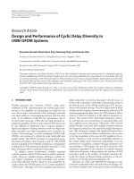
Báo cáo hóa học: " Research Article Dataflow-Based Mapping of Computer Vision Algorithms onto FPGAs" pptx
Bạn đang xem bản rút gọn của tài liệu. Xem và tải ngay bản đầy đủ của tài liệu tại đây (1.13 MB, 12 trang )
Hindawi Publishing Corporation
EURASIP Journal on Embedded Systems
Volume 2007, Article ID 49236, 12 pages
doi:10.1155/2007/49236
Research Article
Dataflow-Based Mapping of Computer Vision
Algorithms onto FPGAs
Mainak Sen,
1
Ivan Corretjer,
1
Fiorella Haim,
1
Sankalita Saha,
1
Jason Schlessman,
2
Tiehan Lv,
2
Shuvra S. Bhattacharyya,
1
and Wayne Wolf
2
1
Department of Electrical and Computer Engineering, University of Maryland, College Park, MD 20742, USA
2
Department of Electrical Engineering, Princeton University, Princeton, NJ 08544, USA
Received 1 May 2006; Revised 8 October 2006; Accepted 9 October 2006
Recommended by Moshe Ben-Ezra
We develop a design methodology for mapping computer vision algorithms onto an FPGA through the use of coarse-grain recon-
figurable dataflow graphs as a representation to guide the designer. We first describe a new dataflow modeling technique called
homogeneous parameterized dataflow (HPDF), which effectively captures the structure of an important class of computer vision
applications. This form of dynamic dataflow takes advantage of the property that in a large number of image processing applica-
tions, data production and consumption rates can vary, but are equal across dataflow gr a ph edges for any particular application
iteration. After motivating and defining the HPDF model of computation, we develop an HPDF-based design methodology that
offers useful properties in terms of verifying correctness and exposing performance-enhancing transformations; we discuss and
address various challenges in efficiently mapping an HPDF-based application representation into target-specific HDL code; and
we present experimental results pertaining to the mapping of a gesture recognition application onto the Xilinx Virtex II FPGA.
Copyright © 2007 Mainak Sen et al. This is an open access article distributed under the Creative Commons Attribution License,
which permits unrestricted use, distribution, and reproduction in any medium, provided the original work is properly cited.
1. BACKGROUND AND MOTIVATION
Computer vision methods based on real-time video analy-
sis form a challenging and increasingly important domain
for embedded system design. Due to their data-intensive
nature, hardware implementations for real-time video are
often more desirable than corresponding software imple-
mentations despite the relatively longer and more compli-
cated development processes associated with hardware im-
plementation. The approach that we pursue in this paper is
based on direct representation by the designer of applica-
tion concurrency using dataflow principles. Dataflow pro-
vides an application modeling paradigm that is well suited
to parallel processing (and to other forms of implementa-
tion streamlining) for digital signal processing (DSP) sys-
tems [1]. Dataflow is effective in many domains of DSP, in-
cluding digital communications, r adar, and video process-
ing.
In this paper, we use dataflow as a conceptual tool
to be applied by the designer rather than as the core of
an automated translation engine for generating HDL code.
This combination of a domain-specific model of computa-
tion, and its use as a conceptual design tool rather than an
automated one allows great flexibility in streamlining higher
level steps in the design process for a particular application.
As an important front-end step in exploiting this flex-
ibility, we employ HPDF (homogeneous parameterized
dataflow) [2] semantics to represent the behavior of the tar-
get gesture recognition system. HPDF is a restricted form of
dynamic dataflow and is not supported directly by any exist-
ing synthesis tools. However, an HPDF-based modeling ap-
proach captures the high-level behavior of our gesture recog-
nition application in a manner that is highly effective for de-
sign verification and efficient implementation. As our work
in this paper demonstrates, the HPDF-based representation
is useful to the designer in structuring the design process and
bridging the layers of algorithm and architecture, wh ile HDL
synthesis tools play the complementary role of bridging the
architecture and the target platform.
2. RELATED WORK
Modeling computer vision applications using dataflow
graphs can lead to useful formal properties, such as bounded
memory requirements, and efficient synthesis solutions [3].
The synchronous dataflow (SDF) model, for example, has
2 EURASIP Journal on Embedded Systems
particularly strong compile time predictability properties
[4]. However, this model is highly restrictive and cannot han-
dle data-dependent execution of dataflow graph vertices (ac-
tors). A cyclostatic dataflow (CSDF) [5] graph can accommo-
date multiphase actors but still does not permit data depen-
dent production or consumption patterns. The token flow
model [6] provides for dynamic actors where the number
of data values (tokens) transferred across a graph edge may
depend on the run-time value of a token that is received at
a “control port” of an incident actor. A metamodeling tech-
nique called parameterized dataflow [7] (PDF) has been pro-
posed in which dynamic dataflow capabilities are formulated
in terms of run-time reconfiguration of actor and edge pa-
rameters.
A number of studies have been undertaken in recent
years on the design and implementation of multimedia ap-
plications on FPGAs using other formal or systematic ap-
proaches. Streams-C [8] provides compiler technology that
maps high-level parallel C language descriptions into circuit-
level netlists targeted to FPGAs. To use Streams-C effectively,
the programmer needs to have some application-specific
hardware mapping expertise as well as expertise in paral-
lel programming under the communicating sequential pro-
cesses (CSP) model of computation [9]. Streams-C consists
of a small number of libraries and intrinsic functions added
to a subset of C that the user must use to derive synthesizable
HDL code.
Handel-C [10] represents another important effort to-
wards developing a hardware oriented C language. Handel-C
is based on a subset of the ANSI C standard along with exten-
sions that support a synchronous parallel mode of operation.
This language also conforms to the CSP model.
Match [11], or AccelFPGA as it is called now, gener-
ates VHDL or Verilog from an algorithm coded in MAT-
LAB, a programming language that is widely used for
prototyping image and video processing algorithms. Ac-
celFPGA has various compiler directives that the designer
can use to explore the design space for optimized hard-
ware implementation. Loop unrolling, pipelining, and user-
defined memory mapping are examples of implementation
aspects that can be coordinated through AccelFPGA direc-
tives.
Compaan [12] is another design tool for translating
MATLAB programs into HDL for FPGA implementation.
Compaan performs its translation through an intermediate
representation that is based on the Kahn process network
model of computation [13].
Rather than adapting a sequential programming lan-
guage for hardware design, as the above-mentioned ap-
proaches do, our approach is based on concurrency ex-
posed by the designer in representing the algorithm as a
dataflow model. This is a useful approach for signal pro-
cessing because the structure of signal processing applica-
tions in terms of its coarse-grain components (e.g., FIR fil-
ters, IIR filters, and FFT computations) often translates intu-
itively into concurrent specifications based on dataflow prin-
ciples.
3. DYNAMIC DATAFLOW MODELING
In this section, we present a brief background on param-
eterized dataflow (PDF), and parameterized synchronous
dataflow (PSDF), and we formulate a new dataflow meta-
modeling technique called homogeneous parameterized
dataflow (HPDF). Like parameterized dataflow, HPDF is a
metamodeling technique that can be applied to any underly-
ing dataflow model of computation M that has a well-defined
notion of a graph iteration. When a model M is used in con-
junction with HPDF or parameterized dataflow, it is called
the base model to which the metamodeling approach is ap-
plied.
3.1. Parameterized dataflow
Parameterized dataflow [7] increases the expressive power
of the underlying base model by providing for run-time re-
configurability of actor and edge parameters in a certain
structured way. When parameterized dataflow is applied to
SDF as the base model, the resulting model of computation
is called parameterized synchronous dataflow (PSDF). The
PSDF model can be viewed as an augmentation of SDF that
incorporates run-time reconfiguration of parameters for ac-
tors, subsystems, and edges.
An actor A in PSDF is characterized by a set of parameters
(params(A)) that control the actor’s functionality, including
possibly its dataflow behavior. Each parameter is either as-
signed a value from a set of viable values or left unspecified.
These unspecified par ameters are assigned values at run time
through a disciplined run-time reconfiguration mechanism.
Techniques have been developed to execute PSDF graphs ef-
ficiently through carefully constructed quasistatic schedules
[7].
PSDF specifications are built up in a modular way in
terms of hierarchical subsystems. Every subsystem is in gen-
eral composed of three subgraphs, called the init, subinit
and body graphs. New parameter values to use during run-
time reconfiguration are generally computed in the init and
subinit g raphs, and the values are propagated to the body
graph, which represents the computational core of the asso-
ciated PSDF subsystem. The init graph is invoked at the be-
ginning of each invocation of the (hierarchical) parent graph
and the subinit graph is invoked at the beginning of each in-
vocation of the associated subsystem followed by the body
graph. Intuitively, reconfiguration of a body graph by the
corresponding init graph occurs less frequently but is more
flexible compared to reconfiguration by the subinit graph
[7].
3.2. Homogeneous parameterized dataflow
In this section, we develop the HPDF model which, like pa-
rameterized dataflow, is a metamodeling technique in that it
can be applied to different dataflow base models. In this sec-
tion, we present the characteristics of the actors, edges, and
delay buffersinanHPDFgraph.
Mainak Sen et al. 3
An HPDF subsystem is homogeneous in two ways. First,
unlike general SDF graphs and other multirate models, the
top level actors in an HPDF subsystem execute at the same
rate. Second, unlike the hier archically oriented parameter-
ized dataflow semantics, reconfiguration across subsystems
can be achieved without introducing hierarchy (i.e., recon-
figuration across actors that are at the same level of the mod-
eling hierarchy). Some dynamic applications are naturally
nonhierarchical (as we show in Section 5), and this kind of
behavior can be modeled using HPDF without imposing “ar-
tificial” hier archical structures that a parameterized dataflow
representation would entail. At the same time, hierarchy can
be used within the HPDF framework when it is desired.
HPDF is a metamodeling technique. Composite actors in
an HPDF model can be refined using any dataflow modeling
semantics that provide a well-defined notion of subsystem it-
eration. For example, the composite HPDF actor might have
SDF, CSDF, PSDF or multidimensional SDF [14]actorsasits
constituent actors.
As with many other dataflow models, such as SDF and
CSDF, an HPDF e edge can have a nonnegative integer delay
δ(e) on it. This delay gives the number of initial data sam-
ples (tokens) on the edge. The stream of tokens that is passed
across an edge needs markers of some kind to indicate the
“packets” that correspond to each iteration of the producing
and consuming actors. An end-of-packet marker is used for
this purpose in our implementation.
Interface actors in HPDF can produce and consume arbi-
trary amounts of data, while the internal connections must,
for fixed parameter values, obey the constraints imposed by
the base model. An HPDF source actor in gener al has access
to a variable number of tokens at its inputs, but it obeys the
semantics of the associated base model on its output. Sim-
ilarly, an HPDF sink actor obeys the semantics of its base
model at the input but can produce a variable number of to-
kens on its output. HPDF source and sink actors can be used
at subsystem interfaces to connect hierarchically to other
forms of dataflow.
3.3. Comparison of HPDF and PSDF
While HPDF employs parameterized actors and subsystems
like PSDF, there are several distinguishing features of HPDF
in relation to PSDF. For example, unlike PSDF, HPDF a l-
ways executes in bounded memory whenever the component
models execute in bounded memory. In contrast, some PSDF
systems do not execute in bounded memory, and in general,
a combination of static and run-time checks is needed to en-
sure bounded memory operation for PSDF [7].
Also, as described in Section 3.2, we do not have to in-
troduce hierarchy in HPDF to account for dynamic behavior
of actors. For example, suppose that a dynamic source ac-
tor A produces n tokens that are consumed by the dynamic
sink actor B. In PSDF, we need to have A and B in different
subsystems; the body of A would set the parameter n,which
will be a known quantity at that time, in the subinit of B
(see Section 5.1 for a more detailed example). This hierarchy
can be avoided in HPDF as we assume that data is produced
and consumed in same-sized blocks. As we will describe fur-
ther in Section 5, this simple form of dynamicity has many
applications in signal processing algorithms. It therefore de-
serves explicit efficient support as provided by HPDF.
In summary, compared to PSDF, HPDF provides for sim-
pler (nonhierarchical) parameter reconfiguration, and for
more powerful static analysis. In exchange for these features,
HPDF is significantly more narrow in the scope of applica-
tions that it is suitable for. Intuitively, a parameterized mul-
tirate application cannot be modeled using HPDF. However,
as we motivate in this paper, HPDF is suitable for an impor-
tant class of computer vision applications, and therefore it
is a useful modeling approach to consider when developing
embedded hardware and software for computer visions sys-
tems.
4. GESTURE RECOGNITION APPLICATION
As a consequence of continually improving CMOS technol-
ogy, it is now possible to develop “smart camera” systems that
not only capture images, but also process image frames in
sophisticated ways to extract “meaning” from video streams.
One important application of smart cameras is gesture recog-
nition from video streams of human subjects. In the ges-
ture recognition algorithm discussed in [15], for each image
captured, real-time image processing is performed to iden-
tify and track human gestures. As the flow of images is in-
creased, a higher level of reasoning about human gestures
becomes possible. This type of processing occurs inside the
smart camera system using advanced ver y large scale inte-
gration (VLSI) circuits for both low-level and high-level pro-
cessing of the information contained in the images. Figure 1
gives an overview of the smar t camera gesture recognition
algorithm.
The functional blocks of particular interest in this paper
are the low-level processing components Region, Contour, El-
lipse,andMatch (within the dotted rectangle in Figure 1).
Each of these blocks operate at the pixel level to identify and
classify human body parts in the image, and are thus good
candidates for implementation on a high-performance field-
programmable gate array (FPGA).
The computational core of the block diagram in Figure 1
can be converted from being an intuitive flow diagram to
a precise behavioral representation through integration of
HPDF modeling concepts. This exposes significant patterns
of parallelism and of predictability, which together with ap-
plication specific optimizations help us to map the applica-
tion efficiently into hardware.
The front-end processing is performed by Region extrac-
tion (Region), which accepts a set of three images as inputs
(we will refer to this set as an image group from now on).
The input images constituting the image group are in the
YC
r
C
b
color space in which Y represents the intensity and
C
r
, C
b
represents the chrominance components of the im-
age. In the current application input, chrominance compo-
nents are downsampled by a factor of two. Thus, the three
4 EURASIP Journal on Embedded Systems
Video
input
Image
duplication
Output
modification
Video
output
Region
extraction
Contour
following
Ellipse
fitting
Graph
matching
HMM
for head
HMM
for torso
HMM
for hand 1
HMM
for hand 2
Gesture
classifier
Recognized
activity
Figure 1: Block level representation of the smart camera algorithm [15].
images in the image group sent as input to Region extraction
are
(i) the Y component (Image 1 in Figure 5);
(ii) the background (Image 2 in Figure 5); and
(iii) the downsampled C
r
, C
b
components together (Image
3inFigure 5).
The image with background regions is used in processing
the other two images, which have foreground information
as well. In one of the foreground images, the Region block
marks areas that are of human-skin tones, and in the other,
it marks areas that are of nonskin tone. Each of these sets of
three images is independent of the next set of three, revealing
image-level parallelism.
Additionally, modeling the algorithm with finer granu-
larity (Section 5.3) exposes that the set of three pixels from
the corresponding coordinates in the images within an im-
age group are independent of any other set of pixels, leading
to pixel-level parallelism. This has been verified by simulat-
ing the model for correct behavior. Furthermore, the oper-
ations performed are of similar complexity, suggesting that
a synchronous pipeline implementation w ith little idle time
between stages is possible.
After separating foreground regions into two images,
each containing only skin and nonskin tone regions respec-
tively, the next processing stage that occurs is contour follow-
ing (Contour). Here, each image is scanned linearly pixel-by-
pixel until one of the regions marked in the Region stage is
encountered. For all regions in both images (i.e., regardless
of skin or nonskin tone), the contour algorithm traces out
the periphery of each region, and stores the (x, y) locations
of the boundary pixels. In this way, the boundary pixels mak-
ing up each region are grouped together in a list and passed
to the next stage.
The ellipse fitting (Ellipse) functional block processes
each of the contours of interest and characterizes their shapes
through an ellipse-fitting algorithm. The process of ellipse
fitting is imperfect and allows for tolerance in the deforma-
tions caused during image capture (such as objects obscuring
portions of the image). At this stage, each contour is pro-
cessed independently of the others, revealing contour-level
parallelism.
Finally, the graph matching (Match) functional block
waits until each contour is characterized by an ellipse before
beginning its processing. The ellipses are then classified into
head, torso, or hand regions based on several factors. The
first stage attempts to identify the head ellipse, which allows
the algorithm to gain a sense of where the other body parts
should be located relative to the head. After classifying the
head ellipse, the algorithm proceeds to find the torso ellipse.
This is done by comparing the relative sizes and locations of
ellipses adjacent to the head ellipse, and using the fact that
the torso is usually larger by some proportion than other re-
gions and that it is within the vicinity of the head. The condi-
tions and values used to make these determinations are part
of a piecewise quadratic Bayesian classifier that only requires
the six characteristic parameters from each el lipse in the im-
age [15].
5. MODELING THE GESTURE RECOGNITION
ALGORITHM
In this section, we model the gesture recognition algorithm
using both PSDF and HPDF, and then show some applica-
tion specific optimizations that are aided by the HPDF rep-
resentation.
5.1. Modeling with PSDF
As mentioned in Section 3.1, PSDF imposes a hierarchy dis-
cipline. The gesture recognition algorithm is modeled us-
ing PSDF in Figure 2. At the uppermost level, the Ges-
Recog. subsystem has empty init and subinit graphs, and
GesRecog.body is the body graph for the subsystem that has
two hierarchical subsystems—H
E
and H
M
. The subsystems
H
E
and H
M
in turn each have two input edges. On one of
these edges, one token is consumed; this token provides the
number of tokens (e.g., the value of p
2
on the edge between
Mainak Sen et al. 5
Specification GesRecog.
R
11
C
p
1
p
2
H
E
11 11
p
3
p
4
H
M
Graph GesRecog.body
Specification H
M
Graph H
M
.subinit
Graph H
M
.init
Sets p
3
= p
4
Sets the values of
p
4
in H
M
.body
11
D
2
p
4
p
4
M
Graph H
M
.body
Specification H
E
Graph H
E
.subinit
Graph H
E
.init
Sets p
1
= p
2
11
D
1
p
2
p
2
E
Graph H
E
.body
Sets the values of
p
2
in H
E
.body
Figure 2: PSDF modeling of the Gesture Recognition application.
C and H
E
in Figure 2) that is to be consumed on the other
edge, which is edge that contains the actual tokens that are to
be processed.
The body graph of H
E
has the actor E embedded inside.
H
E
· init, which is called once per iteration of the GesRecog.
subsystem, has one actor in the graph. This actor sets the pa-
rameters p
1
= p
2
in the body graph. The H
E
· subinit graph
has one actor, which sets in p
2
in H
E
· body with the value
sent by the actor C
· D
1
is a dummy “gain” actor required so
that the schedule in the body graph is p
2
D
1
E to accommo-
date for p
2
tokens as input to E. Analogous behavior is seen
in H
M
· init, H
M
· subinit,andH
M
· body.
5.2. Modeling with HPDF over SDF
We prototyped an HPDF-based model of the gesture recog-
nition algorithm in Ptolemy II [16], a widely used software
tool for experimenting with new models of computation and
integrating different models of computation. Here, we ap-
plied SDF as the base model to which the HPDF metamodel
is applied. Our prototy pe was developed to validate our
HPDF representation of the application, simulate its func-
tional correctness, and provide a reference to guide the map-
ping of the application into h ardware.
In the top level, the HPDF application representa-
tion contains four hierarchical actors (actors that represent
RCEM
11 nn
pp
Figure 3: HPDF model of the application with parameterized token
and consumption rates, where R is Region, C is Contour, E is Ellipse,
and M is Match.
nested subsystems)—Region, Contour, Ellipse, and Match—
as shown in Figure 3. The symbols on the edges represent the
numbersofdatavaluesproducedandconsumedoneachex-
ecution of the actor. Here n and p are parameterized data
transfer rates that are not known statically. Furthermore, the
rates can vary during execution subject to certain technical
restrictions that are imposed by the HPDF model, as de-
scribed in Section 3.2.
5.3. Modeling with HPDF over CSDF
We have further refined our model for the gesture recogni-
tion algorithm using CSDF [17] as the base model for HPDF.
Figure 4 shows that Region can be represented as a CSDF
subsystem with s phases, where s is the number of pixels
in one input frame, and Region can work on a per-pixel
basis (pixel-level parallelism). On the other hand, Figure 4
suggests that Contour needs the whole image frame to start
execution.
6 EURASIP Journal on Embedded Systems
Video
input
Number of phases
= number of pixels = s
(s 1)
(s 1)
(s 1)
(s 1)
(s 1)
(s 1)
Region
extraction
Contour
following
(s 1)
(s 1)
s
s
Figure 4: Model of the static part of the system.
5.4. Modeling the actors
By examining the HPDF graph i n conjunction with the intra-
actor specifications (the actors were sp ecified using Java in
our Ptolemy II prototype), we derived a more detailed rep-
resentation as a major step in our hardware mapping pro-
cess. This representation is illustrated across Figures 5 and 6,
which are lower-level dataflow representations of Region and
Contour, respectively. Here, as with other dataflow diagr ams,
the round nodes (A, B, C, D,andE) represent computations,
and the edges represent unidirectional data communication.
Figures 5 and 6 are created by hand while mapping Re-
gion and Contour to dataflow structures, and the actors A
through E are each implemented in a few lines of Java code.
These are more refined dataflow representations of the actors
in the original HPDF representation. This kind of dataflow
mapping from the corresponding application is a manual
process, and depends on the expertise of the designer as well
as the suitability of the form of dataflow that is being ap-
plied. In this particular case, the actors A to E represent the
following operations (Image I here represents one pixel from
the corresponding Image I and the algorithm runs for all the
pixels in those images, thold
i
represents threshold values de-
scribed in the algorithm):
(i) A represents abs (Image 1-Image 2);
(ii) B represents if (Image 3 > thold
1
);
(iii) C represents if (((A) > thold
2
) ∧ (thold
3
> Image1 >
thold
4
));
(iv) D represents if (A>thold
5
); and
(v) E represents
CD + CB.
The square nodes in Figure 5 represent image buffers or
memory, and the diamond-shaped a nnotations on edges rep-
resent delays. The representation of Figure 5 reveals that even
though buffers Image 1 and Image 3 are being read from
and written into the reading and writing occur in a mu-
tually noninterfering way. Furthermore, separating the two
buffers makes the four-stage pipeline implementation a nat-
ural choice.
In Contour (Figure 6), the dotted edges represent condi-
tional data transfer. In each such conditional edge, zero or
one-data item can be produced by the source actor depend-
ing on its input data. More specifically, in Figure 6 there will
either be one-data value produced on the edge between A and
B or on the self-looped edge, and the other edge will have
zero-data items produced. The representation of Figure 4
and its data transfer properties motivated us to map the as-
sociated functionality into a four-stage self-timed process.
Image 1
Image 2
Image 3
Image 1
Image 3
A
B
C
D
E
Figure 5: Region is shown to be broken into a four-stage pipeline
process.
A
BCD
Figure 6: Contour is shown to have conditional edges and serial ex-
ecution. This structure is implemented as a four-stage self-timed
process.
6. FROM THE MODEL TO HARDWARE
Dataflow modeling of an application has been used exten-
sively as an important step for verification, and for perform-
ing methodical software synthesis [16]. Hardware synthe-
sis from SDF and closely related representations has also
been explored (e.g., see [18–20]). In this paper, we explore
the hardware synthesis aspects for class of dynamic dataflow
representations that can be modeled using HPDF. Com-
pared to PSDF, HPDF can be more suited to intuitive man-
ual hardware mapping because of its nonhierarchical dy-
namic dataflow approach. For example, Figure 3 mig ht sug-
gest a power-aware self-timed architecture, where the differ-
ent hardware modules hibernate and are occasionally awak-
ened by the preceding module in the chain. Alternatively, it
can also suggest a pipelined architecture with four stages for
high performance. The designer can also suggest multiple in-
stantiations of various modules based on applying principles
of data parallelism on the dataflow gr a ph [19]. Such applica-
tion of data parallelism can systematically increase through-
put without violating the dataflow constraints of the appli-
cation. Hence, an HPDF model can suggest a range of use-
ful architectures for an application, and thus aid the designer
significantly in design-space exploration.
In Region, the application level dataflow model (which
shows pixel-level parallelism) in conjunction with actor level
dataflow (which suggests a pipelined architecture) suggests
that the pipeline stages should work on individual pixels and
not on the whole fr a me for maximum throughput. On the
other hand for Contour, a self-timed architecture that per-
formsonthewholeimagewasanaturalchoice.
Mainak Sen et al. 7
In addition to dataflow modeling, we also applied some
application specific transformations. For example, the Ellipse
module utilizes floating-point operations to fit ellipses to
the various contours. The original C code implementation
uses a moment-based initialization procedure along with
trigonometric and square-root calculations. The initializa-
tion procedure computes the averages of the selected contour
pixel locations a nd uses these averages to compute the vari-
ous moments. The total computation cost is
5nC
+
+6nC
−
+3nC
∗
+5C
/
,(1)
where n is the number of pixels in the contour, and each term
C
OP
represents the cost of performing operation OP. In an
effort to save hardware and reduce complexity, the following
transformation was applied to simplify the hardware for cal-
culating averages and moments:
mxx
=
n
i=1
x
i
− x
2
n
=⇒
n
i=1
x
i
2
n
− (x)
2
,(2)
and similarly for mxy and myy. The computational cost after
this transformation is
5nC
+
+3nC
∗
+9C
/
+3C
−
+3C
∗
. (3)
Comparing this w ith the expression for the previous ver-
sion of the algorithm, we observe a savings of 3nC
−
,which
increases linearly with the number of contour pixels, at the
expense of a fixed overhead 4C
/
+3C
∗
. This amounts to a
large overall savings for pr actical image sizes.
Further optimizations that were performed on the
ellipse-fitting implementation included splitting the calcu-
lations into separate stages. This allowed for certain values
(such as nxx, myy, mxy) to be computed in earlier stages and
reused multiple times in later stages to remove unnecessary
computations.
The characterization of ellipses in Match is accomplished
in a serial manner, in particular, information about previ-
ously identified ellipses is used in the characterization of fu-
ture ellipses. Our functional prototype of the matching pro-
cess clearly showed this dependency of later stages on previ-
ous stages. The hardware implementation that we derived is
similar to that of Contour, and employs a six-stage self-timed
process to efficiently handle the less predictable communica-
tion behavior.
7. EXPERIMENTAL SETUP
The target FPGA board chosen for this application is the
multimedia and microblaze development board from Xilinx.
Theboardcanactasaplatformtodevelopawidevariety
of applications such as image processing and ASIC prototyp-
ing. It features the XC2V2000 device of the Virtex II family
of FPGAs.
Some of the more important features of the board in-
clude the following.
(i) Five external independent 512 K
× 36 bit ZBT RAMs.
(ii) A video encoder-decoder.
(iii) An audio codec.
(iv) Support for PAL/NTSC TV input/output.
(v) On-board ethernet support.
(vi) An RS-232 port.
(vii) Two PS-2 serial ports.
(viii) A JTAG port.
(ix) A system ACE-controller and compact flash storage
device to program the FPGA.
7.1. ZBT memory
One of the key features of this board is its set of five fully inde-
pendent banks of 512 k
× 32 ZBT RAM [21] with a maximum
clock rate of 130 MHz. These memory devices support a 36-
bit data bus, but pinout limitations on the FPGA prevent the
use of the four par ity bits. The banks operate completely in-
dependently of one another, as the control signals, address,
data busses, and clock are unique to each bank with no shar-
ing of signals between the banks. The byte write capability is
fully supported as it is the burst mode in which the sequence
starts with an externally supplied address.
Due to the size of the images, we needed to store them us-
ing these external RAMs. A memory controller module was
written in Verilog , simulated, synthesized, and downloaded
onto the board. We then successfully integrated this module
with the Region module.
7.2. RS-232
In order to communicate between the host PC and the board,
we used the RS-232 protocol. We adapted an RS232 con-
troller core with a wishbone interface [22] and configurable
baud rate to write images from the PC to the memory. The
board acts as a DCE device; we implemented the physical
communication using a str aight-through three wire cable
(pins 2, 3, and 5) and used the Windows hyperterminal util-
ity to test it. This interface was integrated into the Region and
memory controller modules and tested in the board.
Figure 7 illustrates the overall experimental setup, in-
cluding the interactions between the PC and the multimedia
board, and between the board and the HDL modules.
8. DESIGN TRADEOFFS AND O PTIMIZATIONS
There were various design decisions made during implemen-
tation of the algorithm, some of which were specific to the
algorithm at hand. In this section, we explore in more de-
tail the tradeoffs that were present in the important design
space associated with memory layout. We also present a step-
by-step optimization that we performed on one of the de-
sign modules for reducing its resource requirements on the
FPGA.
8.1. Memory layout tradeoffs
The board memory resources are consumed by the storing of
the images. Each of the 5 ZBT RAM banks can store 512 K
words that are 32-bits long, for a total storage capacity of 10
8 EURASIP Journal on Embedded Systems
FPGA
REGION
RS-232 controller
ZBT
RAM
Control
state
machine
ZBT RAM
controller
Input Output
PC
Xilinx
multimedia
board
Figure 7: The overall setup interactions among various modules of
our design and components of the multimedia board.
megabytes. Given that each pixel requires one byte of storage
and that there are 384
× 240 pixels per image, 90 kilobytes
of memory are required to store each image. The first mod-
ule, Region, has 3 images as inputs, and 2 images as outputs.
These two images are scanned serially in the second mod-
ule, Contour. The total amount of memory needed for im-
age storing is then 450 kilobytes, less than 5% of the external
memory available on board. However, reorganization of the
images in the memory can dramatically change the number
of memory access cycles performed and the number of banks
used. These tradeoffs also affect the total power consump-
tion.
Several strategies are possible for storing the images in
the memory. The simplest one (Case 1) would be to store
each of the five images in a different memory bank, us-
ing 90 K addresses and the first byte of each word. In this
way, the 5 images can be accessed in the same clock cy-
cle (Figure 8(a)). However, we can minimize the number
of memory banks used by exploiting the identical order in
which the reading and writing of the images occurs (Case 2).
Thus, we can store the images in only two blocks, using each
of the bytes of a memory word for a different image, and still
access all the images in the same clock cycle (Figure 8(b)).
On the other hand, a more efficient configuration in or-
der to minimize the number of memory access cycles (Case
3)wouldbetostoreeachimageinadifferent bank, but
using the four bytes of each memory word consecutively
(Figure 8(c)). Other configurations are possible, for example,
(Case 4) we can have two images per bank, storing 2 pixels of
each image in the same word (Figure 8(d)). Ta ble 1 summa-
rizes the number of banks and memory access cycles needed
for each of these configurations.
Case 3 appears to be the most efficient memory organi-
zation. Here, the time associated with reading and writing
of the images is 69120 memory access cycles, and the total
number of memory access cycles is also the lowest, 161280.
This reduced number of memory access cycles suggests that
power consumption will also be relatively low in this config-
uration. Figure 8 illustrates all of the cases discussed above.
8.2. Floating-point optimizations
Floating-point operations are used throughout the imple-
mentation of the Ellipse and Match blocks. The Ellipse block
processes the (x, y) location of ever y pixel that is along the
border of a contour. From these locations, averages, mo-
ments, and rotation parameters are derived that characterize
a fitted el lipse to the particular contour. An ellipse is uniquely
defined by a set of five parameters—the center of the el-
lipse (dxAvg, dyAvg), its orientation (rotX), and the lengths
of its major and minor axes (aX, aY)[23]. Here, the terms in
the parenthesis are the abbreviations used in this paper (see
Figure 9).
Due to the nonuniform shapes of the contours, the ellipse
fitting is imperfect and introduces some approximation er-
ror. By representing the parameters using floating point val-
ues, the approximations made have more precision than if
integer values were used. To fur ther motivate the need for
floating point numbers, the Match block uses these approx-
imations to classify each ellipse as a head, torso, or hand. To
do so, the relative locations, sizes, and other parameters are
processed to within some hard-coded tolerances for classifi-
cation. As an example, the algorithm considers two ellipses
within a distance Y of each other with one being around X
times larger than the other to be classified as a head/torso
pair. It is because of the approximations and tolerances used
by the algorithm that floating-point representations are de-
sirable, as they allow the algorithm to operate with imperfect
information and still produce reasonable results.
For our implementation, we used the IEEE 1076.3 Work-
ing Group floating-point packages, which are free and easily
available from [24].Thesepackageshavebeenunderdevel-
opment for some time, have been tested by the IEEE Work-
ing Group, and are on a fast track to becoming IEEE stan-
dards. Efficient synthesis of floating point packages involved
the evaluation of floating-point precision required by the
smart camera algorithm. The C code version of the algo-
rithm utilizes variables of type double, which represent 64-
bit floating-point numbers. Utilizing the floating-point li-
brary mentioned before, we were able to vary the size of the
floating-point numbers to see how the loss in precision af-
fected the algorithm outputs as well as the area of the result-
ing synthesized design.
We reduced the number of bits used in the floating-point
number representation and performed a series of simulations
to determine the loss in accuracy relative to the original 64-
bit algorithm. Figure 9 shows the resulting root-mean-square
(RMS) error for various sizes of floating-point numbers. For
the smart camera algorithm, we found that the range from
20- to 18-bit floating-point number representations gave suf-
ficient accuracy, and any lower precision (such as 16-bit)
caused a dramatic increase in the errors. The values that are
most affected by the loss in precision are rotX, aX,andto
Mainak Sen et al. 9
A2
A1
90 K
0
1
Bank 0 Bank 1 Bank 2 Bank 3 Bank 4
B2
B1
C2
C1
D2
D1
E2
E1
(a)
A2
A1
90 K
0
1
B2
B1
C2
C1
D2
D1
E2
E1
(b)
22.5K
0
A1
A2 A3A4 B1 B2 B3 B4 C1 C2C3 C4 D1D2 D3D4 E1 E2 E3 E4
(c)
A3
A1
45 K
0
1
A4
A2
B3
B1
B4
B2
C3
C1
C4
C2
D3
D1
D4
D2
E3
E1
E4
E2
(d)
Figure 8: Image storage distribution. (a) Case 1: each image in a separate bank using only the first byte of the first 90 k words of the memory.
(b) Case 2: three images in bank 0 and two in bank. (c) Case 3: each image in a separate bank but all four bytes used in each word, using
22.5 k words. (d) Case 4: images stored in three banks, each using 2 bytes of the first 45 k words.
some extent aY. These values depend on the computation of
the arctangent function. As the precision is lowered, small
variations cause large changes in the output of arctangent.
The dxAvg and dyAvg parameters are not as affected by the
loss in precision, as the only computations they require are
addition and division.
Since the arctangent and sqrt functions have domains
from
∞ to −∞,andsqrt also has a range of ∞ to −∞, the-
oritically the need might a rise for expressing the whole real
data set. The input image data set on which our experiment
was performed was relatively small, and no prior knowledge
was available of the range of values needed to be expressed
for a new data set that the algorithm might be subjected to.
Thus our choice of floating point over fixed point for imple-
mentation and simulations was motivated by the lack of a
quantization error metric and lack of predictability of the in-
put data set for the low-level processing of the gesture recog-
nition algorithm. Also this low-level processing is a precur-
sor to higher-level gesture recognition algorithms for which,
to our knowledge, no prior metric has been investigated to
determine how errors in low-level processing effect the abil-
ity of the higher-level processing to correctly detect and pro-
cess gestures. Through further simulation and analysis it may
be possible to also determine suitable fixed-point precisions,
however, care must be taken to ensure reliable results espe-
cially for the arctangent function.
10 EURASIP Journal on Embedded Systems
Table 1: Comparison of different memory layout strategies.
Configuration Banks used Read cycles- Write cycles- Read cycles- Total non- Total number
Region Region Contour overlapping cycles of cycles
Case1 5 92160X3 92160X2 184320X1 276480 645120
Case2
2 92160X1 92160X1 184320X1 276480 368640
Case3
5 23040X3 23040X2 46080X1 69120 161280
Case4
3 46080X2 46080X1 92160X1 138240 230400
0
20
40
60
80
100
120
140
Percentage (%)
32 21 20 18 16
(bit)
RMS errors relative to 64 bit
aX
dxAvg
rotX
aY
dyAvg
Figure 9: Comparison of percentages RMS error for different-
length floating point of representations, normalized to a 64-bit
floating-point representation.
Table 2: Synthesis results.
Number of bits Area (in LUTs)
32-bit 110092
21-bit
54944
20-bit
46951
18-bit
41088
16-bit
23923
Tab le 2 presents the area in number of look-up tables re-
quired for each of the floating-point number representations.
As expected, when we reduce the number of bits, the area of
the resulting design decreases, but at the cost of lost preci-
sion.
The number of available LUTs in an FPGA varies heavily
depending on the family of the FPGA and also on the specific
devices within the family. For example, in the Virtex II family
of the Xilinx FPGAs, the XC2V1000 contains 10,240 LUTs,
the XC2V2000 contains 21,504 LUTs, and the XC2V8000
contains 93,184 LUTs. In the Xilinx Virtex II Pro family,
the XC2VP7 contains 9,856 LUTs and XC2VP100 contains
88, 192 LUTs (other intermediate devices in the family are
omitted). In our experimental setup, we used the XC2V2000
FPGA, which did not have enough resources for us to im-
plement Ellipse with the desired precision on the board (our
current implementation involves 16-bit floating point num-
bers and additional optimizations) but a larger FPGA would
have sufficed.
9. RESULTS
In this section, we present some representative results from
both software and hardware implementations of the gesture
recognition algorithm.
We developed a software implementation of the ges-
ture recognition algorithm on a texas instruments (TI) pro-
grammable digital signal processor. We evaluated this im-
plementation using the TI Code Composer Studio version
2 for the C’6xxx family of programmable DSP processors.
The application, when implemented with our HPDF model,
for a C64xx fixed-point DSP processor has a runtime of
21405671 cycles, and with a clock period of 40 nanoseconds,
the execution time was calculated to be 0.86 second. The
scheduling overhead for the implementation is minimal, as
the HPDF representation inherently leads to a highly stream-
lined quasistatic schedule. The worst-case buffer size for an
image of 348
× 240 pixels was 184 kilobytes on the edge be-
tween Region and Contour, 642 Kb between Contour and
Ellipse, and 34 Kb between Ellipse and Match for a total of
860 kilobytes. The original code (without modeling) had a
run-time of 27741882 cycles, and with the same clock pe-
riod of 40 nanoseconds, the execution time was 1.11 seconds.
Thus, HPDF-based implementation improved the execution
time by 23 percent.
To further take advantage of the parallelism exposed by
HPDF modeling, we implemented both the Region and Con-
tour functions in hardware. We used ModelSim XE II 5.8c
for HDL simulation, Synplify Pro 7.7.1 for synthesis of the
floating-point modules, and Xilinx ISE 6.2 for synthesis of
nonfloating-point modules, and for downloading the bit-
stream into the FPGA. Figures 10, 11,and12 show the out-
puts of the first two processing blocks (Region and Con-
tour, resp.) after they were implemented in HDL. Comparing
these outputs with the outputs of the software implementa-
tion verified the correctness of the HDL modules.
10. CONCLUSIONS
In this paper, we have developed homogeneous parameter-
ized dataflow (HPDF), an efficient metamodeling technique
for capturing a commonly occurring restricted form of dy-
namic dataflow that is especially relevant to the computer vi-
sion domain. HPDF captures the inherent dataflow structure
Mainak Sen et al. 11
Region
Figure 10: Our HDL representation of Region transforms the im-
age on the left to the o utput of the right.
Contour
Figure 11: Actual transformation to the image done by HDL repre-
sentation of Contour.
Contour
Figure 12: Part of Figure 10 zoomed-in and colored to show the
effect of Contour.
in such applications without going into more complicated
hierarchical representations or into more general dynamic
dataflow modeling approaches where key analysis and syn-
thesis problems become impossible to solve exactly.
We have also developed and applied a novel design
methodology for effective platform-specific FPGA imple-
mentation of computer vision applications based on the
HPDF modeling technique. In particular, we have used
HPDF to model a gesture recognition algorithm that exhibits
dynamically varying data production and consumption rates
between certain pairs of key functional components.
The top-level HPDF model and subsequent intermedi-
ate representations that we derived from this model naturally
suggested efficient hardware architectures for implementa-
tion of the main subsystems. The hardware description lan-
guage (HDL) code for the four modules of the algorithm
was developed follow ing these suggested architectures. The
modules were then verified for correctness, and synthesized
to target a multimedia board from Xilinx. Memory manage-
ment and fl oating point handling also played a major role
in our design process. We explored various t radeoffs in these
dimensions and through the framework of our HPDF-based
application representation, we integrated our finding s seam-
lessly with the architectural decisions described above.
ACKNOWLEDGMENTS
This research was supported by Grant no. 0325119 from the
US National Science Foundation. The multimedia board tar-
geted in our experiments was donated by Xilinx, Inc.
REFERENCES
[1] S. Sriram and S. S. Bhattacharyya, Embedded Multiprocessors:
Scheduling and Synchronization , Marcel Dekker, New York,
NY, USA, 2000.
[2] M. Sen, S. S. Bhattacharyya, T. Lv, and W. Wolf, “Modeling
image processing systems with homogeneous parameterized
dataflow graphs,” in Proceedings of IEEE International Confer-
ence on Acoustics, Speech and Signal Processing (ICASSP ’05),
vol. 5, pp. 133–136, Philadelphia, Pa, USA, March 2005.
[3] S. S. Bhattacharyya, R. Leupers, and P. Marwedel, “Software
synthesis and code generation for signal processing systems,”
IEEE Transactions on Circuits and Systems II: Analog and Digi-
tal Signal Processing, vol. 47, no. 9, pp. 849–875, 2000.
[4] E. Lee and D. Messerschmitt, “Synchronous data flow,” Pro-
ceedings of the IEEE, vol. 75, no. 9, pp. 55–64, 1987.
[5] G. Bilsen, M. Engels, R. Lauwereins, and J. Peperstraete,
“Cyclo-static dataflow,” IEEE Transactions on Signal Processing,
vol. 44, no. 2, pp. 397–408, 1996.
[6] J. T. Buck, “A dynamic dataflow model suitable for efficient
mixed hardware and software implementations of DSP ap-
plications,” in Proceedings of the 3rd International Workshop
on Hardware/Software Codesign (CODES ’94), pp. 165–172,
Grenoble, France, September 1994.
[7] B. Bhattacharya and S. S. Bhattacharyya, “Parameterized
dataflow modeling for DSP systems,” IEEE Transactions on Sig-
nal Processing, vol. 49, no. 10, pp. 2408–2421, 2001.
[8] M. Gokhale, J. Stone, J. Arnold, and M. Kalinowski, “Stream-
oriented FPGA computing in the Streams-C high level
language,” in Proceedings of IEEE Symposium on Field-
Programmable Custom Computing Machines, pp. 49–56, Napa
Valley, Calif, USA, April 2000.
[9] C.A.R.Hoare,Communicating Sequential Processes, Prentice-
Hall, New York, NY, USA, 1985.
[10] S. Chappell and C. Sullivan, “Handel-C for co-processing &
co-design of Field Programmable System on Chip,” White Pa-
per, Celoxica, Oxford, UK, September 2002.
[11] P. Banerjee, D. Bagchi, M. Haldar, A. Nayak, V. Kim, and
R. Uribe, “Automatic conversion of floating-point MATLAB
programs into fixed-point FPGA based hardware design,” in
Proceedings of the 41st Annual Design Automation Conference
(DAC ’04), pp. 484–487, San Diego, Calif, USA, June 2004.
[12] B. Kienhuis, E. Rijpkema, and E. Deprettere, “Compaan: de-
riving process networks from Matlab for embedded signal
processing architectures,” in Proceedings of the 18th Interna-
tional Workshop on Hardware/Software Codesign (CODES ’00),
pp. 13–17, San Diego, Calif, USA, May 2000.
[13] G. Kahn, “The semantics of s imple language for parallel pro-
gramming,” in Proceedings of IFIP Congress, pp. 471–475,
Stockholm, Sweden, August 1974.
[14] E. A. Lee, “Multidimensional streams rooted in dataflow,” in
Proceedings of the IFIP Working Conference on Architectures
and Compilation Techniques for Fine and Medium Grain Paral-
lelism, no. 23, pp. 295–306, Orlando, Fla, USA, January 1993.
[15] W. Wolf, B. Ozer, and T. Lv, “Smart cameras as embedded sys-
tems,” Computer, vol. 35, no. 9, pp. 48–53, 2002.
[16] J. Eker, J. W. Janneck, E. A. Lee, et al., “Taming heterogeneity—
the ptolemy approach,” Proceedings of the IEEE, vol. 91, no. 1,
pp. 127–144, 2003.
12 EURASIP Journal on Embedded Systems
[17] F.Haim,M.Sen,D I.Ko,S.S.Bhattacharyya,andW.Wolf,
“Mapping multimedia applications onto configurable hard-
ware with parameterized cyclo-static dataflow graphs,” in Pro-
ceedings of IEEE International Conference on Acoustics, Speech
and Signal Processing (ICASSP ’06), vol. 3, pp. 1052–1055,
Toulouse, France, May 2006.
[18] J. Horstmannshoff,T.Gr
¨
otker, and H. Meyr, “Mapping mul-
tirate dataflow to complex RT level hardware models,” in Pro-
ceedings of the International Conference on Application-Specific
Systems, Architectures and Processors (ASAP ’97), pp. 283–292,
Zurich, Switzerland, July 1997.
[19] M. Sen and S. S. Bhattacharyya, “Systematic exploitation of
data parallelism in hardware synthesis of DSP applications,”
in Proceedings of IEEE International Conference on Acoustics,
Speech and Signal Processing (ICASSP ’04), vol. 5, pp. 229–232,
Montreal, Quebec, Canada, May 2004.
[20] M. C. Williamson and E. A. Lee, “Synthesis of parallel
hardware implementations from synchronous dataflow graph
specifications,” in Proceedings of the 30th Asilomar Conference
on Signals, Systems and Computers, vol. 2, pp. 1340–1343,
Grove, Calif, USA, November 1996.
[21] Data-sheet for ZBT memory, />Products/.
[22] OpenCores Organization, “WISHBONE System-on-Chip
(SoC) Interconnection Architecture for Portable IP Cores,” re-
vision B.3, September 2002, .
[23] A. K. Jain, Fundamentals of Digital Image Processing, Prentice-
Hall, New York, NY, USA, 1989.
[24] IEEE Working Group, />200x-ft/packages/files.html.