Báo cáo hóa học: " Research Article Efficient Integration of Pipelined IP Blocks into Automatically Compiled Datapaths Andreas Koch" pdf
Bạn đang xem bản rút gọn của tài liệu. Xem và tải ngay bản đầy đủ của tài liệu tại đây (754.43 KB, 9 trang )
Hindawi Publishing Corporation
EURASIP Journal on Embedded Systems
Volume 2007, Article ID 65173, 9 pages
doi:10.1155/2007/65173
Research Article
Efficient Integration of Pipelined IP Blocks into
Automatically Compiled Datapaths
Andreas Koch
Embedded Systems and Applications Group, Technical University of Darmstadt, FB20, Hochschulstraße 11,
64289 Darmstadt, Germany
Received 14 May 2006; Revised 4 August 2006; Accepted 14 September 2006
Recommended by Juergen Teich
Compilers for reconfigurable computers aim to generate problem-specific optimized datapaths for kernels extracted from an input
language. In many cases, however, judicious use of preexisting manually optimized IP blocks within these datapaths could improve
the compute performance even further. The integration of IP blocks into the compiled datapaths poses a different set of problems
than stitching together IPs to form a system-on-chip; though, instead of the loose coupling using standard busses employed by
SoCs, the one between datapath and IP block must be much tighter. To this end, we propose a concise language that can be
efficiently synthesized using a template-based approach for automatically generating lightweight data and control interfaces at the
datapath level.
Copyright © 2007 Andreas Koch. This is an open access article distributed under the Creative Commons Attribution License,
which permits unrestricted use, distribution, and reproduction in any medium, provided the original work is properly cited.
1. INTRODUCTION
Automatic high-level language compilers [1, 2]areoneof
the prime means to make the compute power of reconfig-
urable computers available to developers. However, despite
the progress in such compile flows, the generated hardware
often does not reach the quality of designs carefully op-
timized by an expert designer. Thus, it becomes desirable
to tightly integrate optimized custom IP blocks with the
compiler-generated datapath.
While this mixed method is still new in the world of
hardware design, it has been established for decades in the
software area. There, it is quite common to call highly op-
timized assembly code libraries (e.g., for math or graph-
ics) from high-level programming languages. Thanks to
well-defined binary interface and calling conventions, cross-
abstraction level calls are easily performed.
For hardware design, the situation is much more com-
plex. One of the reasons appears to be the increased flexibility
of custom hardware compared to a fixed-function processor:
the same functionality can be realized in dedicated hardware
in many different ways and thus be perfectly matched to the
rest of the system environment.
However, automatically building a complete system-on-
chip from these disparate components is difficult. While
some attempts have been made to standardize on-chip com-
munications [3–5], they have not achieved total success.
Many IP blocks still do not use one of these proposed stan-
dard interfaces, but instead rely on their own custom inter-
faces, which have to be “wrapped” before connecting to a
standard bus.
Furthermore, when compiling an accelerator unit for
a reconfigurable computer, the generated hardware should
fully exploit the adaptive nature of the target architecture:
reconfigurability allows the use of highly efficient problem-
specific hardware structures, instead of the more general ap-
proaches (e.g., networks-on-chip) that are often used in the
ASIC world.
Thus, instead of using a general-purpose communica-
tions structure to assemble a system-on-chip, we are aim-
ing for the tight integration of a larger number of smaller
IP blocks directly into the compiled datapaths. For this ap-
plications, the standard busses mentioned above are gener-
ally too heavyweight, with specialized high-bandwidth low-
latency point-to-point connections being far preferable.
One of the tasks that has to be performed to achieve this
goal is the creation of interface controllers that translate from
the various IP-specific protocols for initialization, data ex-
change, and so forth, to a common protocol compatible with
the central data path controller. Ideally, the creation of the
2 EURASIP Journal on Embedded Systems
wrappers should be performed “on-the-fly” during hardware
compilation, without requiring time-consuming HDL-based
synthesis steps. However, the wrappers must be capable of
handling even complex control schemes and pipelined oper-
ation. Prior work [6, 7] has already detailed the UCODE, a
simple language for concisely describing such interface con-
trollers. We now contribute a novel way to quickly synthe-
size hardware from UCODE: a subcircuit “template” is as-
sociated with each kind of UCODE instruction; these tem-
plates are then composed following the UCODE descrip-
tion to build the entire interface controller circuit. As will
be shown in Section 6,area/timetradeoffscaneasilybeper-
formed by changing the templates and mapping rules.
2. RELATED WORK
Flexibly connecting mismatched interfaces has been the sub-
ject of many research e fforts. The approaches range from
constructing product FSMs to build protocol converters [8]
using libraries of interface modules [9, 10] to extracting e vent
graphs from timing diagrams [11]. A good overview and a
formal model of the problem can be found in [12].
However, none of these methods matches our scenario
of tightly integrating preexisting IP blocks into automatically
compiled datapaths. For this tight degree of coupling, the FI-
FOs proposed in [13] are inappropriate. In our usage sce-
nario, FIFOs for each IP block would inordinately increase
the latency of the entire data path. Thus, our approach aims
to avoid the introduction of additional delay elements.
Another common approach [13, 14] relies on extracting
the interface description from the HDL code of the IP blocks.
With the increasing use of encrypted soft-cores or netlist-
only firm cores, this approach becomes rather impractical. To
avoid these difficulties, we rely on UCODE as an IP-external
description of interface characteristics.
Pipelining, a feature crucial for high throughput datap-
aths, is also often lacking from the approaches listed here.
Therehavebeensomeefforts to apply a data-flow-based ap-
proach to the problem, but they sometimes lack flexibility.
For example, the technique in [15] can only handle static
data-flow and requires a fixed send-receive protocol. Other
work, such as [16], is more flexible, but does not cover the
direct hardware mapping of the described primitives. In this
text, we extend UCODE as a flexible description for interface
protocols with an efficient mapping onto ac tual hardware.
3. TARGET ARCHITECTURE
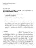
Our application setting is shown in Figure 1.IPblocksare
to be inserted into compiler-generated datapath by automat-
ically synthesizing a thin wrapper both on the data and the
control sides, connected using dedicated point-to-point links
to the datapath and the global controller. This global con-
troller is responsible for higher-level control decisions (e.g.,
switching an IP block into another operating mode, start-
ing/canceling speculative execution). The wrapper controller
in turn acts on a lower level and orchestrates the control se-
quencing and data exchange within a function selected by
the global controller. On the data side, the formats used in
Compiled datapath
Operator
Operator
Operator
IP
block
Wrapper
Operator
Operator
Data flow
Local
controllers
Global controller
Control flow
Figure 1: Application scenario.
the datapath and on the IP block are assumed to be mostly
compatible. However, minor transformations, such as serial-
to-parallel conversions, bus (de)composition, and physical-
logical port renaming are supported in the wrapper.
The following sections will discuss how to concisely de-
scribe the wrapper function, the manner of integration with
the global controller, the actual template-based synthesis,
and optimized mapping of the abstract circuit to real hard-
ware.
4. INTERFACE DESCRIPTION
Similar to the approach in [14, 16], we compose the de-
scriptions of the controller functions from a small num-
ber of primitives. However, we also allow the description of
pipelining, port renaming, and embedded wired logic. All of
our primitives (called UCODEs) have been defined in terms
of underlying abstract hardware functions. These templates
can be composed and then efficiently mapped to the tar-
get architecture (but not necessarily exactly as depicted, see
Section 6).
When a new IP block is prepared for automatic integra-
tion, it is the task of a human expert to author the corre-
sponding UCODE descriptions for the various capabilities of
the block. These descriptions will general ly be manually ex-
tracted from the data sheets and manuals delivered by the IP
vendor .
In this work, we concentrate on the low-level description
and template-based synthesis of the wrapper. The complete
specification [7] also covers higher-level constructs such as
initialization, parallel/serial execution modes, and so forth.
4.1. Compute model
Despite the hardware-centric formulation of our controller
behavior, the underlying model of computation has formal
roots in Petri nets: the presence of a token (logic “1”) in-
dicates an active state, multiple states may be active at the
same time, and tokens may be created, deleted, and rerouted
during the controller execution. All of our primitives accept
Andreas Koch 3
io := iomode [{ portmap }];
iomode :
= io comb | io seq “;”;
io
comb := “LEVEL”;
io
seq := (“POSEDGE” | “NEGEDGE”) [repeat];
repeat :
= “∗” count;
count :
= cardinal;
portmap :
= “(” physport logport “)”;
physport :
= port | literal;
logport :
= port | literal;
literal :
= cardinal;
port :
= name [“[” [msb “:”] lsb “]”];
msb :
= cardinal;
lsb :
= cardinal;
Figure 2: Input/Output primitives.
a token, many also propagate it (possibly after modification).
The global controller activates a wrapper controller by in-
jecting an initial token into the first state. In a similar fash-
ion, a token leaving the final state can indicate completion
of the wrapper operation and transfer control back to the
global controller. Pipelining, however, requires additional in-
frastruc ture (described in Section 5).
4.2. Input/Output
Compared to [14], I/O has been unified here (no distinction
is made between control and data) and extended (we explic-
itly model time, currently defined by edges of a single clock
domain).
The I/O operations shown in Figure 2 are initially distin-
guished by whether they operate combinationally or sequen-
tially. In the first case, the UCODE statement LEVEL is used,
in the second one, the POSEDGE and NEGEDGE statements will
be employed. The latter differentiate between synchronizing
to the rising or falling edge of the central clock.
Note that the textual syntax shown here is purely a
human-readable convenience. After it has been written to de-
scribe a specific IP block, UCODE is only handled within
design tools, and can thus be represented more efficiently
in binary form. For example, our current implementa-
tion of a UCODE-based tool flow actually uses Java object
graphs for efficient storage and manipulation of the UCODE
descriptions: the programs are stored as sequences of state-
ment objects; and textual references, for example, to I/O
ports, have been replaced by direct references to the corre-
sponding design database objects. Figure 3 shows an exam-
ple for such a UCODE fragment embedded in Java. The frag-
ment shown describes the memory write operation of a value
datain to address addr viaacacheinterface[17].
As primary arguments, each of the primitives takes a set
of portmap pairs, each pair associating a physical port with a
logicalportonabusorsubbusbasis.Suchapairrepresentsa
permanent (wire) or temporary (muxed/demuxed) connec-
tion between the two ports. Alternatively, one of the ports
may be replaced by a constant literal. This indicates the ap-
plication of the literal value to the remaining port of the pair.
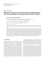
Figure 4 shows the underlying hardware templates of the
sequential operators. When the state is activated by an arriv-
ing “1” token, the associated action occurs: in the input case
(a), the selected logical input port is applied to the specified
physical port of the IP block in time to be sampled for the
next clock edge. In the control case (b), the presence of the
token indicates the application of a literal value (generated by
the literal logic) to one or more physical ports of the IP Block.
Finally, in the output case (c), the given physical output port
is applied to the selected logical output to be sampled into a
datapath register at the next clock edge. After the clock edge,
indicated by the UCODE, the token is then propagated.
The combinational I/O operations depicted in Figure 5
operate similarly. The cr ucial difference is the now purely
combinational nature of the operation (no time steps as de-
fined by clock edges pass).
It is obvious that the final logic blocks controlling the
multiplexers and the datapath control inputs must be com-
posed by merging the logic blocks of all UCODEs that apply
to the same port.
Consider the following example: assume that an IP block
implements the logical behavior mul(prod,a,b). The phys-
ical interface, however, has a single input port D. Both the
multiplicator and the multiplicand are loaded into the block
through this single port, but on successive clock cycles. The
loading process must be started by raising the control input
S. After accepting the multiplicand, the result becomes valid
on the physical output port Y four clocks later and can then
be sampled back into the datapath on the following clock
edge.
Figure 6 shows the UCODE description of both the con-
trol and data interfaces in the wrapper. The abst ract (tech-
nology independent) circuit for this description can be gen-
erated simply by composing the templates and merging the
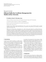
logic blocks (Figure 7). Due to the simplicity of the example,
the logic blocks are trivial or have even been optimized away
entirely (e.g., since there is a 1-1 mapping of the physical port
Y to the logical port prod, no demultiplexer and associated
control logic are required). The hardware was composed by
chaining the circuits underlying the UCODE primitives via
their token inputs and outputs. For each primitive, the form
appropriate for data (ports D, Y) or control (port S) manip-
ulation is employed.
The shift and wired logic operations mentioned in Sec-
tion 4 are realized by offsetting the msb and lsb indices of
physical and logical ports against each other. The UCODE in
Figure 8(a) sign-extends the 4b physical port D to map to the
8b logical port x. In a similar fashion, split ports may be han-
dled. The code in Figure 8(b) assembles two physical ports to
map to a wider logical port. The expression in Figure 8(c)
converts a 22b word address on PA to a byte-oriented address
addr.
4.3. Control flow
While the I/O primitives can already handle simple IP blocks
on their ow n, many blocks have more complex interfacing re-
quirements. Two of the most common ones are handshaking
4 EURASIP Journal on Embedded Systems
//UCODE for cache write operation
Seq ucwrite
= newFSeq(); //createemptysequenceofUCODEobjects
ucwrite.cat ( // combinationally apply data and control signals
new Level (
new FSeq (
new PortValue (CACHE
OE, 0),
new PortValue (CACHE
WE, 1),
new PortPort (CACHE
ADDR, addr),
new PortPort (new BusPort (CACHE
WIDTH 16BIT), new BusPort (width, 0)),
new PortPort (new BusPort (CACHE
WIDTH 8BIT), new BusPort (width, 1)),
new PortPort (CACHE
WRITE, datain))));
ucwrite.cat ( // wait for cache port ready
new Continue (new PortValue (CACHE
STALL, 0)));
ucwrite.cat ( // signals must be kept stable to next edge for sampling by cache port
new PosEdge (new FSeq (
new PortValue (CACHE
OE, 0),
new PortValue (CACHE
WE, 1),
new PortPort (CACHE
ADDR, addr),
new PortPort (new BusPort (CACHE
WIDTH 16BIT), new BusPort (width, 0)),
new PortPort (new BusPort (CACHE
WIDTH 8BIT), new BusPort (width, 1)),
new PortPort (CACHE
WRITE, datain))));
Figure 3: Example for UCODE embedded in Java.
and (closely related) variable execution times (latencies). For
these cases, the straightline execution of the I/O UCODEs no
longer suffices. The CONTINUE UCODE shown in Figure 9 is
similar to the wait for event primitive in [14], but extends the
concept by allowing logical expressions in a sum-of-products
form.
Each portequals states that the indicated physical port (or
bit subrange thereof) must be equal to the given literal value.
The UCODE waits in the current I/O state until all condi-
tions within a CONTINUE become true (logical product), or
that any of a group of successive CONTINUE primitives match
(logical sum).
The hardware templates underlying this UCODE are
shown in Figure 10. The condition logic is derived by AND-
ing the conditions within each CONTINUE and ORing these
separate outputs for successive CONTINUE statements.
The statement operates by routing an incoming token
back to the last active I/O statement. Only if the joint con-
dition of all successive CONTINUE statements becomes true,
will the token continue past the UCODE to the next state-
ment. The CONTINUE itself is purely combinational. A syn-
chronous mode of execution can be achieved by following
the CONTINUE w ith one of the sequential I/O statements
POSEDGE or NEGEDGE.
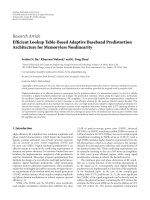
As an example, reconsider the integration of the Mult
16
× 16 IP block of the previous section. But here, instead
of the fixed latency of four clock cycles, the IP block in-
dicates the availability of a result in time for the next ris-
ing clock edge using a “1” on the physical port R.The
corresponding UCODE fragment is shown in Figure 11, the
corresponding hardware in Figure 12.
The back-edge of the CONTINUE statement routes the
token to the input of previous I/O statement (the second
POSEDGE of the fragment). Due to the trivial condition,
the condition logic collapses to a single wire from R to
the CONTINUE hardware. In a more complex application,
the logic would hold the sum-of-products realization of the
intra- and inter-statement conditions.
4.4. Pipelining
For our application of tightly integrating an IP block into a
heavily pipelined datapath, it is crucial to be able to describe
pipelining characteristics. Specifically, we want to be able to
model the prologue, the steady-state, and the epilogue of a
pipelined IP block. START, shown in Figure 13, separates the
prologue from the steady state. It also merges an incoming
token from the back-edge into the forward direction (begin-
ning the next pipeline iteration).
RESTART (Figure 14) indicates the beginning of the epi-
logue and duplicates an incoming token: one copy is passed
forward into the epilogue of the pipeline iteration, the
other copy is passed backward into the START circuitry,
beginning the next pipeline iteration in the steady-state.
RESTART effectively creates a new thread of execution which
results in multiple states becoming ac tive in parallel (Petri
net-like). Figure 15 shows the pipeline modeled by these
UCODEs.
Andreas Koch 5
Log in
Log in
Log in
Phys. in
Select logic
Token in Token out
DQ
(a) Data input interface
IP block
Literal logic
Token in Token outDQ
(b) Control interface
Phys. out
Log outDQ
CE
Select logic
Toke n in
Toke n ou t
Datapath
register
DQ
(c) Data output interface
Figure 4: Sequential I/O templates.
Log in
Log in
Log in
Phys. in
Select logic
Token in Token out
(a) Data input interface
IP block
Literal logic
Toke n in
Toke n ou t
(b) Control interface
Phys. out
Log out
DQ
CE
Select logic
Toke n in
Toke n ou t
Datapath
register
(c) Data output interface
Figure 5: Combinational I/O templates.
Only one START/RESTART combo may exist within a
UCODE program. This construct is the only way to actually
iterate within the wrapper controller. All other loops must be
realized in the global controller by repeatedly activating the
wrapper controller. Furthermore, exploiting pipeline paral-
lelism requires additional circuitr y around the wrapper con-
troller for cleanly terminating (draining) the pipeline. This
will be discussed in Section 5.
To give an example on the use of pipelining, we will stay
with our regular multiplier, but posit this time that it has a
total latency of seven cycles (including loading the operands)
and allows pipelined operation with an initiation interval
of four cycles (then the next operands can be loaded). The
UCODE description in Figure 16 models this behavior.
This UCODE fragment has an empty prologue, but the
steady-state and epilogue follow the model of Figure 15.The
corresponding hardware is shown in Figure 17.
5. PIPELINE ADMINISTRATION
The abstract wrapper circuits created from the UCODE
templates can be modified to optionally provide additional
capabilities for the global controller. These extensions in-
clude cleanly stopping the pipeline and waiting for it to drain.
For clarity of the following figures, we show only the abstract
state flip-flops, but omit the combinational logic (e.g., for
CONTINUE statements) in between.
5.1. Stopping the pipeline
This functionalit y is provided by adding a global-control-
ler manipulated input LastIn into the back-edge from
RESTART to START via an AND with inverted input (Fig-
ure 18(a)). It is crucial that this gate is inser ted directly pre-
ceding the D input of the abstract flip-flop, otherwise the con-
trol signals generated by this POSEDGE or NEGEDGE statement
(the mux control in the figure) would become invalid prema-
turely. By asserting LastIn simultaneously with the applica-
tion of the last set of input data a, the final pipeline iteration
will be started.
5.2. Draining the pipeline
With var iable-latency elements in the pipeline, it becomes
difficult for the global controller to determine when the
6 EURASIP Journal on Embedded Systems
POSEDGE (S 1) (D[15 : 0] a[15 : 0]);
POSEDGE (S 0) (D[15 : 0] b[15 : 0]);
POSEDGE; POSEDGE; POSEDGE; POSEDGE;
POSEDGE (Y[31 : 0] prod[31 : 0]);
Figure 6: UCODE for multiplier example.
a
b
1
0
Mult16
16
DY
S
Prod
DQ
CE
Datapath
Start
token
DQ DQ DQ DQ DQ DQ DQ
Finish
token
Figure 7: Wrapper for multiplier IP block.
(a) POSEDGE (D[3] x[7]) (D[3] x[6])
(D[3] x[5]) (D[3] x[4])
(D[3 : 0] x[3 : 0]);
(b) POSEDGE (H[15 : 0] data[31 : 16])
(L[15 : 0] data[15 : 0]);
(c) POSEDGE (PA[21 : 0] addr[23 : 2])
(0 addr[1 : 0]);
Figure 8: Wired logic and shifts.
continue := “CONTINUE” { portequals } “;”;
portequals :
= “(” physport literal “)”;
Figure 9: Flow control.
Control in
Condition logic
Toke n in
Toke n ou t
Toke n ou t
to last I/O
statement
Figure 10: Control fl ow templates.
POSEDGE (S 1) (D[15 : 0] a[15 : 0]);
POSEDGE (S 0) (D[15 : 0] b[15 : 0]);
CONTINUE (R 1);
POSEDGE (Y[31 : 0] prod[31 : 0]);
Figure 11: UCODE for variable latency multiplier.
a
b
1
0
Mult16
16
DY
SR
Prod
DQ
CE
Datapath
Start
token
DQ
DQ
DQ
Finish
token
Figure 12: Wrapper for variable latency multiplier.
Toke n in
Toke n ou t
Toke n in
from RESTART
Figure 13: Pipeline steady-state join template.
last data item has been completely processed. Two basic ap-
proaches present themselves: one method detects whether
the pipeline is empty by checking that no abstract flip-flop
holds a valid token and asserts the port PipeEmpty in that
case. Depending on the speed/area requirements and the ca-
pabilities of the target technology, this can be realized either
in a serial or in parallel fashion (Figure 18(b) and (c)). If any
slow-downduetocascadedorverywidelogicgatesisun-
acceptable, the approach shown in Figure 19 can be used.
While it completely avoids long combinational paths, it re-
quires double the number of abstract flip-flops.
6. OPTIMIZED MAPPING
Even though we have expressed the precise semantics of the
individual UCODE statements in terms of composed ab-
stract hardware templates, this by no means indicates that the
actually implemented hardware must have the same struc-
ture. On the contrary, in many cases it is beneficial to map
only an optimized form of the wr apper to the target tech-
nology. Since our primary target are FPGAs, specifically the
Xilinx Virtex FPGA architectures, we will discuss some pro-
cedures applicable to these devices.
While our abstract model of one flip-flop per state (one-
hot encoded) has advantages both in theory (easy mod-
eling of parallel states) and in practice (distributed con-
troller, less routing congestion), in certain cases the flip-flop
Andreas Koch 7
Toke n in
Toke n ou t
Toke n ou t
to START
Figure 14: Pipeline steady-state fork template.
POSEDGE
POSEDGE
START
POSEDGE
POSEDGE
RESTART
POSEDGE
POSEDGE
Prologue
Steady state
Epilogue
Figure 15: Model of pipeline structure.
START;
POSEDGE (S 1) (D[15 : 0] a[15 : 0]);
POSEDGE (S 0) (D[15 : 0] b[15 : 0]);
POSEDGE; POSEDGE;
RESTART;
POSEDGE; POSEDGE;
POSEDGE (Y[31 : 0] prod[31 : 0]);
Figure 16: UCODE for pipelined multiplier.
requirements exceed the capabilities even of flip-flop rich ar-
chitectures. In these cases, target-specific blocks such as dedi-
cated shift registers (SRL16) can be employed. Also, the pres-
ence of the * (repeat) operator indicates that a given de-
lay in itself is not pipelined and can be densely mapped to
a counter. Conventional logic synthesis and mapping algo-
rithms [18, 19] are used in a tightly focused fashion to mini-
mize and map the various logic blocks associated with some
UCODE operators.
This composing of templates in UCODE order and the
selective application of limited-scope logic synthesis require
only short computation times. They can thus be performed
“on-the-fly” during the high-level language compile flow,
avoiding a full-scale HDL synthesis step involving complex
external tools.
7. EXPERIMENTAL RESULTS
The UCODE language described here has already been used
for interfacing of simple [20] and larger IP blocks [21]toau-
tomatically generated datapaths.
a
b
1
0
Mult16
16
DY
S
Prod
DQ
CE
Datapath
Start
token
DQ DQ DQ DQ DQ DQ DQ
Finish
token
Figure 17: Wrapper for pipelined multiplier.
Table 1: Results of template-based synthesis.
Synthesis style Virtex-II slices Max. clock [MHz]
One-Hot 25 467
Counter
13 248
SRL16
8 243
To show the use of a medium-complexity IP block,
Figure 20 depicts the UCODE for wrapping the Xilinx Logi-
Core 16-Point FFT [22]. After programming the operating
mode, it accepts a 16-sample block of time-domain data. Af-
ter the end of the computation is indicated, 16 frequency-
domain samples can be unloaded from the IP block. In a
pipelined fashion, the next set of time-domain can be pro-
vided to the core when it becomes available again.
Tab le 1 shows the area and time tradeoffs when map-
ping the abstract hardware to the Virtex-II architecture
directly one-hot encoded and using architecture-specific
blocks (counters, shift-registers) on a speedgrade
−4device.
8. FUTURE WORK
The UCODEs introduced in this work form the core of the
specification. However, for reliably interfacing with large IP
blocks (e.g., media codecs) in context of [21], we have de-
fined extensions such as timeouts and exception handling in
the CONTINUE statement that integ rate easily and with only
minimal hardware overhead into the existing semantics and
template-synthesis framework.
While our applications have not required it to date, ir-
regular schedules could be handled elegantly by extending
the CONTINUE statement with an implicit conflict controller
[23, 24], thus avoiding the need for large condition logic
blocks in the wrapper controller.
9. CONCLUSION
Our lightweight approach (compared to full-scale protocol
conversion) has proven suitable for practical use. Easily au-
thored concise UCODE descriptions allow the tight integra-
tion even of complex IP blocks into compiled datapaths with
minimal computational effor t. Instead of full HDL synthe-
sis, simple mapping tools aware of some technology-specific
features suffice to implement the actual circuits from the
composed templates. The UCODE language and underlying
8 EURASIP Journal on Embedded Systems
a
b
1
0
LastIn
DQ
CE
Datapath
PipeEmpty
PipeEmpty
DQ DQ DQ DQ
Start
token
(a)
(b)
(c)
Figure 18: Stopping and combinationally draining the pipeline.
LastIn
a
b
1
0
DQ
CE
Datapath
Start
token
DQ
CE
DQ
CE
DQ
CE
DQ
CE
PipeEmpty
DQ DQ DQ DQ
Figure 19: Sequentially draining the pipeline.
; initialize
POSEDGE (CE 1) (SCALE
MODE 0)
(FWD
INV 1) (START 1)
POSEDGE (START 0)
;startofsteady-state
START
; wait for acceptance of first FFT block
CONTINUE (MODE
CE 1)
; write 16 time domain samples
POSEDGE
∗16 (DI R[15 : 0] time r[15 : 0])
(DI
I[15 : 0] time i[15 : 0])
; fork control flow for pipelining
RESTART
; wait for transformed data
CONTINUE (DONE 1)
; read 16 frequency domain samples
POSEDGE
∗16 (XK R[15 : 0] freq r[15 : 0])
(XK
I[15 : 0] freq i[15 : 0])
Figure 20: UCODE for wrapping 16-point FFT.
compute model are also easily extended to accommodate fu-
ture integration requirements.
By using UCODE descriptions to automatically generate
efficient interface wrappers, the combination of optimized IP
blocks and automatically created datapaths can increase the
performance of a flow targeting an adaptive computer in a
manner similar to transparently calling assembly language
routines from a high-level language. The complexity of the
calling and parameter transfer mechanisms are hidden from
the user by the abstraction of the UCODE description.
REFERENCES
[1] Y. Li, T. Callahan, E. Darnell, R. Harr, U. Kurkure, and J. Stock-
wood, “Hardware-software co-design of embedded reconfig-
urable architectures,” in Proceedings of 37th Design Automation
Conference (DAC ’00), pp. 507–512, Los Angeles, Calif, USA,
June 2000.
[2] N. Kasprzyk and A. Koch, “High-level-language compilation
for reconfigurable computers,” in Proceedings of European
Workshop on Reconfigurable Communication-Centric SoCs (Re-
CoSoc ’05), Montpellier, France, June 2005.
[3] VSI Alliance, “Virtual Component Interface Standard Version
2,” 2001, .
[4] ARM, “AMBA Specification Rev 2.0,” 2001, .
com/products/solutions/AMBA
Spec.html.
[5] IBM, “Core Connect Bus Architecture,” 1999, http://www-3.
ibm.com/chips/techlib/techlib.nsf/productfamilies/Core
Connect
Bus Architecture.
[6] A. Koch, “On tool integration in high-performance FPGA de-
sign flows,” in Proceedings of 9th International Workshop on
Field-Programmable Log ic and Applications (FPL ’99), pp. 165–
174, Glasgow, UK, August-September 1999.
Andreas Koch 9
[7] A. Koch, “FLAME: a flexible API for module based envi-
ronments,” Tech. Rep. 2004-01, EIS, Technical University of
Braunschweig, Braunschweig, Germany, 2004.
[8] R. Passerone, J. A. Rowson, and A. Sangiovanni-Vincentelli,
“Automatic synthesis of interfaces between incompatible pro-
tocols,” in Proceedings of 35th Desig n Automation Conference
(DAC ’98), pp. 8–13, San Francisco, Calif, USA, June 1998.
[9]J.S.SunandR.W.Brodersen,“Designofsysteminterface
modules,” in Proceedings of IEEE/ACM International Confer-
ence on Computer-Aided Design (ICCAD ’92), pp. 478–481,
Santa Clara, Calif, USA, November 1992.
[10] B. Lin and S. Vercauteren, “Synthesis of concurrent system in-
terface modules with automatic protocol conversion genera-
tion,” in Proceedings of IEEE/ACM International Conference on
Computer-Aided Design (ICCAD ’94), pp. 101–108, San Jose,
Calif, USA, November 1994.
[11]P.Chou,R.B.Ortega,andG.Borriello,“Interfaceco-
synthesis techniques for embedded systems,” in Proceedings o f
IEEE/ACM International Conference on Computer-Aided De-
sign (ICCAD ’95), pp. 280–287, San Jose, Calif, USA, Novem-
ber 1995.
[12] V. D’silva, A. Sowmya, S. Parameswaran, and S. Ramesh, “A
formal approach to interface synthesis for system-on-chip
design,” Tech. Rep. UNSW-CSE-TR-304, University of New
South Wales, Sydney, Australia, 2003.
[13] J. Smith and G. De Micheli, “Automated composition of hard-
ware components,” in Proceedings of 35th Design Automation
Conference (DAC ’98), pp. 14–19, San Francisco, Calif, USA,
June 1998.
[14] S. Narayan and D. D. Gajski, “Interfacing incompatible proto-
cols using interface process generation,” in Proceedings of 32nd
Design Automation Conference (DAC ’95), pp. 468–473, San
Francisco, Calif, USA, June 1995.
[15] H.Jung,K.Lee,andS.Ha,“Efficient hardware controller syn-
thesis for synchronous dataflow graph in system level design,”
in Proceedings of 13th International Symposium on System Syn-
thesis (ISSS ’00), pp. 79–84, Madrid, Spain, September 2000.
[16] J. Teifel and R. Manohar, “Static tokens: using dataflow to
automate concurrent pipeline synthesis,” in Proceedings of
10th International Symposium on Advanced Research in Asyn-
chronous Circuits and Systems (ASYNC ’04), pp. 17–27, Crete,
Greece, April 2004.
[17] H. Lange and A. Koch, “Memory access schemes for config-
urable processors,” in Proceedings of 10th International Work-
shop on Field-Programmable Logic and Applications (FPL ’00),
pp. 615–625, Villach, Austria, August 2000.
[18] E. M. Sentovich, K. J. Singh, L. Lavagno, et al., “SIS: a system
for sequential circuit synthesis,” Tech. Rep. UCB/ERL M92/41,
Electrical Engineering and Computer Sciences Department,
University of California, Berkeley, Calif, USA, May 1992.
[19] J. Cong and Y. Ding, “FlowMap: an optimal technology map-
ping algorithm for delay optimization in lookup-table based
FPGA designs,” IEEE Transactions on Computer-Aided Design
of Integrated Circuits and Systems, vol. 13, no. 1, pp. 1–12, 1994.
[20] T. Neumann and A. Koch, “A generic library for adaptive
computing environments,” in Proceedings of 11th International
Conference on Field-Programmable Logic and Applications (FPL
’01), pp. 503–512, Belfast, Northern Ireland, UK, August 2001.
[21] H. Lange and A. Koch, “Hardware/software-codesign by auto-
matic embedding of complex IP cores,” in Proceedings of 14th
International Conference on Field Programmable Logic and Ap-
plication (FPL ’04), pp. 679–689, Leuven, Belgium, August-
September 2004.
[22] Xilinx, “High-Performance 16-Point Complex FFT/IFFT
V1.0,” product specification, 2001.
[23] E.S.Davidson,L.E.Shar,A.T.Thomas,andJ.H.Patel,“Ef-
fective control for pipelined computers,” in Proceedings of 10th
IEEE Computer Society International Conference (COMPCON
’75), pp. 181–184, San Francisco, Calif, USA, February 1975.
[24] P. Schaumont, B. Vanthournout, I. Bolsens, and H. De
Man, “Synthesis of pipelined DSP accelerators with dynamic
scheduling,” in Proceedings of 8th International Symposium
on System Synthesis (ISSS ’95), pp. 72–77, Cannes, France,
September 1995.