Báo cáo hóa học: " Research Article Efficient Multichannel NLMS Implementation for Acoustic Echo Cancellation" doc
Bạn đang xem bản rút gọn của tài liệu. Xem và tải ngay bản đầy đủ của tài liệu tại đây (1.02 MB, 6 trang )
Hindawi Publishing Corporation
EURASIP Journal on Audio, Speech, and Music Processing
Volume 2007, Article ID 78439, 6 pages
doi:10.1155/2007/78439
Research Article
Efficient M ultichannel NLMS Implementation for
Acoustic Echo Cancellation
Fredric Lindstrom,
1
Christian Sch
¨
uldt,
2
and Ingvar Claesson
2
1
Konftel AB, Research and Development, Box 268, 90106 Umea, Sweden
2
Department of Signal Processing, Blekinge Institute of Technology, 37225 Ronneby, Sweden
Received 31 May 2006; Revised 9 November 2006; Accepted 14 November 2006
Recommended by Kutluyil Dogancay
An acoustic echo cancellation structure with a single loudspeaker and multiple microphones is, from a system identification per-
spective, generally modelled as a single-input multiple-output system. Such a system thus implies specific echo-path models (adap-
tive filter) for every loudspeaker to microphone path. Due to the often large dimensionality of the filters, which is required to model
rooms with standard reverberation time, the adaptation process can be computationally demanding. This paper presents a selec-
tive updating normalized least mean square (NLMS)-based method which reduces complexity to nearly half in practical situations,
while showing superior convergence speed performance as compared to conventional complexity reduction schemes. Moreover,
the method concentrates the filter adaptation to the filter which is most misadjusted, which is a typically desired feature.
Copyright © 2007 Fredric Lindstrom et al. This is an open access article distributed under the Creative Commons Attribution
License, which permits unrestricted use, distribution, and reproduction in any medium, provided the original work is properly
cited.
1. INTRODUCTION
Acoustic echo cancellation (AEC) [1, 2] is used in telecon-
ferencing equipment in order to provide high quality full-
duplex communication. The core of an AEC solution is an
adaptive filter which estimates the impulse response of the
loudspeaker enclosure microphone (LEM) system. Typical
adaptive algorithms for the filter update procedure in the
AEC are the least mean square, normalized least mean square
(LMS, NLMS) [3], affine projection (AP), a nd recursive least
squares (RLS) algorithms [4]. Of these, the NLMS-based al-
gorithms a re popular in industrial implementations, thanks
to their low complexity and finite precision robustness.
Multimicrophone solutions are frequent in teleconfer-
encing equipment targeted for larger conference rooms. This
paper considers a system consisting of one loudspeaker and
three microphones. The base unit of the system contains the
loudspeaker and one microphone and it is connected to two
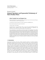
auxiliary expansion microphones, as shown in Figure 1.Such
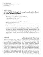
multimicrophone system constitutes a single-input multiple-
output (SIMO) multichannel system with several system im-
pulse responses to be identified, Figure 2. Thus, the signal
processing task can be quite computational demanding.
Several methods for computational complexity reduction
of the LMS/NLMS algorithms have been proposed and ana-
lyzed, for example, [5–14]. In this paper a related low com-
plexity algorithm for use in a multimicrophone system is
proposed.
2. COMPLEXITY REDUCTION METHODS
The LEM system can be modelled as a time invariant lin-
ear system, h(k)
= [h
0
(k), , h
N−1
(k)]
T
,whereN − 1is
the order of the finite impulse response (FIR) model [11]
and k is the sample index. Thus, the desired (acoustic echo)
signal d(k)isgivenbyd(k)
= h(k)
T
x(k), where x(k) =
[x(k), , x(k − N +1)]
T
and x(k) is the input (loudspeaker)
signal. The measured (microphone) signal y(k) is obtained
as y(k)
= d(k)+n(k), where n(k) is near-end noise. As-
suming an adaptive filter
h(k)oflengthN is used, that is,
h(k) = [
h
0
(k), ,
h
N−1
(k)]
T
, the NLMS algorithm is given
by
e(k)
= y(k) −
d(k) = y(k) − x(k)
T
h(k), (1)
β(k)
=
μ
x(k)
2
+
,
h(k +1)=
h(k)+β(k)e(k)x(k),
(2)
2 EURASIP Journal on Audio, Speech, and Music Processing
MIC3
MIC1
MIC2
LS
Figure 1: AEC unit with expansion microphones.
h
1
h
2
h
3
h
1
h
2
h
3
Figure 2: Schematic picture over multimicrophone system mod-
elled as a single-input multiple-output system.
where
d(k) is the estimated echo, e(k) the error (echo can-
celled) signal, β(k) the step-size,
x(k)
2
= x(k)
T
x(k) the
squared Euclidian norm, μ the step size control parameter,
and
a regularization parameter [4].
Low-complexity per iodical and partial updating schemes
reduce the computational complexity of the LMS/NLMS by
performing only a part of the filtering update, (2). The peri-
odic NLMS performs the filter update only at periodical sam-
ple intervals. This updating can be distributed over the in-
termediate samples [5]. The sequential NLMS updates only
a part of the N coefficients at every sample in a sequential
manner [5]. Several methods for choosing which coefficients
to update at what sample instant have been proposed, for ex-
ample, choosing a subset containing the largest coefficients in
the regressor vector [6], low-complexity version of largest re-
gressor vector coefficient selection [7], block-based regressor
vector methods [8, 9], and schemes based on randomization
in the update procedure [10]. The updating can also be based
on assumptions of the unknown plant [11, 12]. Another ap-
proach of omitting updates is possible in algorithms where
the step size is zero for a large number of updates [13, 14].
In a SIMO-modelled M microphone system, there are M
adaptive filters
h
m
(k)withm ∈{1, , M}, to be updated at
each sample, that is,
h
m
(k +1)=
h
m
(k)+
μe
m
(k)x(k)
x(k)
2
+
m = 1, , M,(3)
see Figure 2 for an example with M
= 3. The updating
scheme proposed in this paper explores the possibility of
choosing between the different update equations based on
comparison between the M different error signals e
m
(k).
3. THE PROPOSED ALGORITHM
An adaptive linear filtering process can generally be divided
in two parts the filtering (1) and the adaptation (2). In an
echo cancellation environment, the filtering part gener a lly
is performed at every sample instant in order to produce a
constant audio stream. Although it is most often efficient
Table 1: Example to illustrate the matrix E(k).
Sample index Filter 1 Filter 2 Filter 3
k e
1
(k) e
2
(k) e
3
(k)
k
− 1 Update e
2
(k − 1) e
3
(k − 1)
k
− 2 X e
2
(k − 2) Update
k
− 3 X Update X
(in terms of convergence) to perform filter updating at ev-
ery sample instant, it is not necessary. In practice, this might
not even be possible due to complexity issues. This especially
applies to acoustic echo cancellation environments where the
dimension of the system filters is large.
One approach in a M-microphone system is to update
only one adaptive filter every sample in a round-robin man-
ner, that is, periodic NLMS. This also ensures equal (for all
filters) and predictable convergence since the update occur-
rences are deterministic. The disadvantage is that conver-
gence is slow.
This paper proposes another updating method which in-
stead updates the filter with the largest output error. To illus-
trate the method, assume that M
= 3 (3 adaptive filters), the
present sample index is k, and filter 1 was updated at sample
index k
− 1, filter 3 at k − 2, and filter 2 at k − 3, as illus-
trated in Table 1. Thus, the available errors that can be used
in the update at the present sample index k are e
1
(k)forfilter
1, e
2
(k), e
2
(k − 1) and e
2
(k − 2) for filter 2, and e
3
(k)and
e
3
(k − 1) for filter 3. For example, the error e
1
(k − 2) cannot
be used since it is related to the configuration of filter 1 prior
to the latest update. From the available er rors, the algorithm
chooses the error with the largest magnitude and then per-
forms the corresponding update (compare with (6)and(7)
below).
An algorithm for the method is as follows. After filter-
ing all M-output channels according to (1), the output errors
fromallfiltersareinsertedinaL
× M matrix
E(k)
=
e
1
(k) e
2
(k) e
3
(k) e
M
(k)
E
(k − 1)
,(4)
where M is the number of adaptive filters (channels) and L
determines the number of previous samples to consider. The
L
− 1 × M matrix E(k − 1) consists of the L − 1upperrows
of E(k
− 1), that is,
E(l +1,m, k)
= E(l, m, k − 1) l = 1, , L − 1,
m
= 1, , M,
(5)
where l and m denote row and column indexes, respectively,
and E(l, m, k) is the element at row l and column m in E(k).
The decision of which filter to update and with what out-
put error (and corresponding input vector) is determined by
the element in E(k) with maximum absolute value,
e
max
(k) = max
l,m
E(l, m, k)
l = 1, , L,
m
= 1, , M.
(6)
The row and column indexes of the element in E(k) with the
maximum absolute value are denoted l
max
(k)andm
max
(k).
Fredric Lindst rom et al. 3
For clarity of presentation, the sample index is omitted, that
is, l
max
= l
max
(k)andm
max
= m
max
(k).
The filter corresponding to the row index m
max
, that is,
the filter
h
m
max
(k), is then updated with
h
m
max
(k +1)=
h
m
max
(k)+
μe
max
(k)x
k − l
max
+1
x
k − l
max
+1
2
+
. (7)
This filter update of filter
h
m
max
(k) will make the error el-
ements E(l, m
max
, k), l = 1, , L obsolete, since these are er-
rors generated by
h
m
max
(k) prior to the update. Consequently,
to avoid future erroneous updates, these elements should be
set to 0, that is, set
E
l, m
max
, k
=
0forl = 1, , L. (8)
An advantage over periodic NLMS is that the proposed struc-
ture does not limit the update to be based on the current in-
put vector x(k), but allows updating based on previous input
vectors as well, since the errors not yet used for an update are
stored in E(k). Further, largest output-error update will con-
centrate the updates to the corresponding filter. This is nor-
mally a desired feature in an acoustic echo cancellation envi-
ronment with multiple microphones. For example, consider
the setup in Figure 1 with all adaptive filters fairly converged.
If then one of the microphones is dislocated, this results in an
echo-path change for the corresponding adaptive filter. Nat-
urally, it is desired to concentrate all updates to this filter.
4. ANALYSIS
In the previously described scenario, where several input
vectors are available but only one of them can be used for
adaptive filter updating (due to complexity issues), it might
seem intuitive to update with the input vector correspond-
ing to the largest output error magnitude. In this section, it
is shown analytically that, under certain assumptions, choos-
ing the largest error maximizes the reduction.
The error deviation vector for the mth filter v
m
(k)isde-
fined as v
m
(k) = h
m
(k) −
h
m
(k), and the mean-squared de-
viation as D(k)
= E{v
m
(k)
2
},whereE{·} denotes ex-
pectation [4]. Assume that no near-end sound is present,
n(k)
= 0, and no regularization is used, = 0, and that
the errors available for updating filter m are e
m
(k − l
m
)with
l
m
= 0, , L
m
and L
m
<L, that is, the available errors in ma-
trix E(k) that correspond to filter m. Updating filter m using
error e
m
(k − l
m
)gives
v
m
(k +1)
2
=
v
m
(k) − β(k)e
m
k − l
m
x
k − l
m
2
(9)
and by using
e
m
k − l
m
= x
k − l
m
T
v
m
(k) = v
m
(k)
T
x
k − l
m
(10)
in (9), the following is obtained:
v
m
(k +1)
2
= v
m
(k)
T
v
m
(k) −
2μ − μ
2
x
k − l
m
2
e
2
m
k − l
m
.
(11)
Thus, the difference in mean-square deviation from one sam-
ple to the next is given by
D
m
(k +1)− D
m
(k) =−
2μ − μ
2
E
e
2
m
k − l
m
x
k − l
m
2
,
(12)
which corresponds to a reduction under the assumption that
0 <μ<2.
Further, assuming small fluctuations in the input energy
x(k)
2
from one iteration to the next, that i s, assuming
x(k)
2
=
x(k − 1)
2
=···=
x
k − L
m
+1
2
, (13)
gives [4],
D
m
(k +1)− D
m
(k) =−
2μ − μ
2
E
e
2
m
k − l
m
E
x(k)
2
. (14)
The total reduction r(k) in deviation, considering all M fil-
ters is thus
r(k)
=
M
m=1
D
m
(k +1)− D
m
(k). (15)
Only one filter is updated each time instant. Assume error
E(l, m, k) is chosen for the update. Then r(k)isgivenby
r(k)
=−
2μ − μ
2
E
E
2
(l, m, k)
E
x(k)
2
. (16)
From (16), it can be seen that the reduction is maximized if
e
max
(k), (see (16)), is chosen for the update, that is, as done
in the proposed algorithm.
The proposed algorithm can b e seen as a version of the
periodic NLMS. Analysis of convergence, stability, and ro-
bustness for this branch of (N)LMS algorithms are provided
in, for example, [5, 15].
5. COMPLEXITY AND IMPLEMENTATION
The algorithm proposed in this paper is aimed for imple-
mentation in a general digital signal processor (DSP), typi-
cally allowing multiply add and accumulate arithmetic oper-
ations to be performed in parallel with memory reads and/or
writes (e.g ., [16]). In such a processor, the filtering operation
can be achieved in N instructions and the NLMS update will
require 2N instructions. Both the filtering and the update re-
quire two memory reads, one addition and one multiplica-
tion per coefficient, which can be performed by the DSP in
one instruction. However, the result from the filter update is
not accumulated but it needs to be written back to memory.
Therefore, the need for two instructions per coefficient for
the update operation.
4 EURASIP Journal on Audio, Speech, and Music Processing
Suppose an M-channel system with the same number of
adaptive filters, all with the length of N. The standard NLMS
updating thus requires 3MN DSP instructions.
Updating the matrix E(k), (4), can be implemented using
circular buffering and thus requires only M store instructions
(possible pointer modifications disregarded), while clearing
of E(k), (8), takes a maximum of L instructions (also dis-
regarding possible pointer modifications). Searching for the
maximum absolute valued e lement in E(k), (6), requires a
maximum of 2LM instructions (LM abs-instructions and
LM max-instructions). The parameter
x(k)
2
can be cal-
culated very efficient through recursion, that is,
x(k)
2
=
x(k − 1)
2
+ x
2
(k) − x
2
(k − N), (17)
and its computational complexity can be disregarded in this
case.
All together, this means that the number of DSP instruc-
tions required for the proposed solution can be approxi-
mated with
MN + M + L +2ML +2N. (18)
Foracousticechocancellation,N is generally quite large
(>1000) due to room reverberation time. In this case, we typ-
ically have N
L and N M, which means that (18)is
approximately N(M + 2). The complexity reduction in com-
parison w ith standard NLMS updating is then
M +2
3M
, (19)
which for M
= 3 gives a complexity reduction of nearly a half
(5/9). For higher values of M,thereductionisevenlarger.
Further reduction in complexity can also be achieved if up-
dates are performed say every other or every third sample.
6. SIMULATIONS
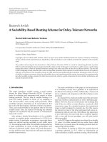
The performance of the proposed method was evaluated
through simulations with speech as input signal. Three im-
pulse responses (h
1
, h
2
,andh
3
), shown in Figure 3,all
of length N
= 1800 were measured with three micro-
phones, according to the constellation in Figure 1,inanor-
mal office. The acoustic coupling between the loudspeaker
and the closest microphone, AC1, was manually normal-
ized to 0 dB and the coupling between the loudspeaker and
the second and third microphones, AC2 and AC3, were
then estimated to
−6dB and −7 dB, respectively. Thus,
10 log
10
(h
2
2
/h
1
2
) =−6 dB and 10 log
10
(h
3
2
/h
1
2
)
=−7dB.
Output signals y
1
(k), y
2
(k), and y
3
(k) were obtained by
filtering the input signal x(k) with the three obtained impulse
responses and adding noise,
y
1
(k) = x(k)
T
h
1
+ n
1
(k),
y
2
(k) = x(k)
T
h
2
+ n
2
(k),
y
3
(k) = x(k)
T
h
3
+ n
3
(k).
(20)
0 200 400 600 800 1000 1200 1400 1600 1800
Coefficient index
1
0.5
0
0.5
1
h
1
0 200 400 600 800 1000 1200 1400 1600 1800
Coefficient index
0.5
0
0.5
h
2
0 200 400 600 800 1000 1200 1400 1600 1800
Coefficient index
0.5
0
0.5
h
3
Figure 3: Impulse responses used in the simulations.
The noise sources n
1
(k), n
2
(k), and n
3
(k) were indepen-
dent, but had the same characteristics (bandlimited flat spec-
trum). Echo-to-noise ratio was approximately 40 dB for mi-
crophone 1 and 34 dB and 33 dB for microphones 2 and 3,
respectively.
In the simulations four low-complexity methods of sim-
ilar complexity were compared; the periodic (N)LMS [5],
random NLMS (similar to SPU-LMS [10]) selecting which
filter to be updated in a stochastic manner (with all fi lters
having equal probability of an update), M-Max NLMS [6],
and the proposed NLMS. The performance of the full update
NLMS is also shown for comparison. The periodic NLMS,
random NLMS, and the proposed method limit the updates
to one whole filter at each time interval, while M-Max NLMS
instead updates all filters but only does this for a subset (1/3
in this case) of all coefficients. However, since M-Max NLMS
requires sorting of the input vectors, the complexity for this
method is somewhat larger (2 log
2
N + 2 comparisons and
(N
−1)/2memorytransfers[9]). Zero initial coefficients were
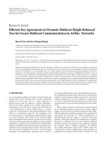
used for all filters and methods. The result is presented in
Figure 4, where the normalized filter mismatch, calculated as
10 log
10
h
m
−
h
m
(k)
2
h
m
2
m = 1, 2, 3, (21)
for the three individual filters and solutions are presented.
Of the four variants with similar complexity, the proposed
method is clearly superior to the conventional periodic
Fredric Lindst rom et al. 5
0 20 40 60 80 100 120
Seconds
50
40
30
20
10
0
Mismatch (dB)
Filter 1
NLMS updated every sample
Periodic NLMS
Proposed NLMS updating scheme
Random NLMS
M-Max NLMS
0 20 40 60 80 100 120
Seconds
40
30
20
10
0
Mismatch (dB)
Filter 2
NLMS updated every sample
Periodic NLMS
Proposed NLMS updating scheme
Random NLMS
M-Max NLMS
0 20 40 60 80 100 120
Seconds
40
30
20
10
0
Mismatch (dB)
Filter 3
NLMS updated every sample
Periodic NLMS
Proposed NLMS updating scheme
Random NLMS
M-Max NLMS
Figure 4: Mismatch for the the evaluated methods.
NLMS and also to the random NLMS. The performance of
the M-Max NLMS and the proposed solution is comparable,
although the proposed solution performs better or equal for
all filters.
The algorithm automatically concentrates computational
resources to filters with large error signals. This is demon-
strated in Figure 5, where filter 2 undergoes an echo-path
change, that is, a dislocation of the microphone. In Figure 5,
0 20 40 60 80 100 120
Seconds
50
40
30
20
10
0
Mismatch (dB)
Filter 1
NLMS updated every sample
Periodic NLMS
Proposed NLMS updating scheme
Random NLMS
M-Max NLMS
0 20 40 60 80 100 120
Seconds
40
30
20
10
0
Mismatch (dB)
Filter 2
NLMS updated every sample
Periodic NLMS
Proposed NLMS updating scheme
Random NLMS
M-Max NLMS
0 20 40 60 80 100 120
Seconds
40
30
20
10
0
Mismatch (dB)
Filter 3
NLMS updated every sample
Periodic NLMS
Proposed NLMS updating scheme
Random NLMS
M-Max NLMS
Figure 5: Mismatch for the the evaluated methods, where an echo-
path change occurs for filter 2 after 55 seconds.
it can be seen that the proposed algorithm basically follows
the curve of the full update NLMS immediately after the
echo-path changes.
If one specific microphone is subject to an extreme
acoustic situation, for example, it is placed in another room
or placed immediately next to a strong noise source, there is
a r isk of “getting stuck,” that is, the corresponding filter has
large output error for all input vectors and thus is updated all
6 EURASIP Journal on Audio, Speech, and Music Processing
the time. This problem can be reduced by setting a limit on
the lowest rate of updates for a filter, that is, if filter m has not
been updated for the last U samples it is forced to update the
next iteration. However, this does not resolve the issue opti-
mally. A more sophisticated method is to monitor the echo
reduction of the filters and bypass or reduce the resources
allocated to filters not providing significant error reduction.
Implementing these extra functions will of course add com-
plexity.
7. CONCLUSIONS
In an acoustic multichannel solution with multiple adaptive
filters, the computation power required to update all filters
every sample can be vast. This paper has presented a solution
which updates only one filter every sample and thus signifi-
cantly reduces the complexity, while still performing well in
terms of convergence speed. T he solution also handles echo-
path changes well, since the most misadjusted filter gets the
most computation power, which often is a desirable feature
in practice.
ACKNOWLEDGMENT
The authors would like to thank the Swedish Knowledge
Foundation (KKS) for funding.
REFERENCES
[1] E. H
¨
ansler and G. Schmidt, Acoustic Echo and Noise Control:
A Practical Approach, John Wiley & Sons, New York, NY, USA,
2004.
[2] M. M . Sondhi, “An adaptive echo canceler,” Bell System Tech-
nical Journal, vol. 46, no. 3, pp. 497–510, 1967.
[3]B.WidrowandS.D.Stearns,Adaptive Signal Processing,
Prentice-Hall, Englewood Cliffs, NJ, USA, 1985.
[4] S. Haykin, Adaptive Filter Theory, Prentice-Hall, Englewood
Cliffs, NJ, USA, 4th edition, 2002.
[5] S. C. Douglas, “Adaptive filters employing partial updates,”
IEEE Transactions on Circuits and Systems II: Analog and Digi-
tal Signal Processing, vol. 44, no. 3, pp. 209–216, 1997.
[6] T. Aboulnasr and K. Mayyas, “Complexity reduction of the
NLMS algorithm via selective coefficient update,” IEEE Trans-
actions on Signal Processing, vol. 47, no. 5, pp. 1421–1424,
1999.
[7] P. A. Naylor and W. Sherliker, “A short-sort M-Max NLMS
partial-update adaptive filter with applications to echo can-
cellation,” in Proceedings of IEEE International Conference on
Acoustics, Speech, and Signal Processing (ICASSP ’03), vol. 5,
pp. 373–376, Hong Kong, April 2003.
[8] K. Doganc¸ay and O. Tanrikulu, “Adaptive filtering algorithms
with selective partial updates,” IEEE Transactions on Circuits
and Systems II: Analog and Digital Signal Processing, vol. 48,
no. 8, pp. 762–769, 2001.
[9] T. Schertler, “Selective block update of NLMS type algo-
rithms,” in Proceedings of IEEE International Conference on
Acoustics, Speech, and Signal Processing (ICASSP ’98), vol. 3,
pp. 1717–1720, Seattle, Wash, USA, May 1998.
[10] M. Godavarti and A. O. Hero III, “Partial update LMS algo-
rithms,” IEEE Transactions on Signal Processing, vol. 53, no. 7,
pp. 2382–2399, 2005.
[11] E. H
¨
ansler and G. Schmidt, “Single-channel acoustic echo
cancellation,” in Adaptive Signal Processing, J. Benesty and Y.
Huang, Eds., Springer, New York, NY, USA, 2003.
[12] S. M. Kuo and J. Chen, “Multiple-microphone acoustic echo
cancellation system with the partial a daptive process,” Digital
Signal Processing, vol. 3, no. 1, pp. 54–63, 1993.
[13] S. Gollamudi, S. Kapoor, S. Nagaraj, and Y F. Huang, “Set-
membership adaptive equalization and an updator-shared im-
plementation for multiple channel communications systems,”
IEEE Transactions on Signal Processing, vol. 46, no. 9, pp. 2372–
2385, 1998.
[14] S.Werner,J.A.ApolinarioJr.,M.L.R.deCampos,andP.S.
R. Diniz, “Low-complexity constrained affine-projection algo-
rithms,” IEEE Transactions on Signal Processing, vol. 53, no. 12,
pp. 4545–4555, 2005.
[15] W. A. Gardner, “Learning characteristics of stochastic-
gradient-descent algorithms: a general study, analysis, and cri-
tique,” Signal Processing, vol. 6, no. 2, pp. 113–133, 1984.
[16] ADSP-BF533 Blackfin processor hardware reference,AnalogDe-
vices, Norwood, Mass, USA, 2005.