Báo cáo hóa học: "Efficient and Secure Fingerprint Verification for Embedded Devices" ppt
Bạn đang xem bản rút gọn của tài liệu. Xem và tải ngay bản đầy đủ của tài liệu tại đây (1.29 MB, 11 trang )
Hindawi Publishing Corporation
EURASIP Journal on Applied Signal Processing
Volume 2006, Article ID 58263, Pages 1–11
DOI 10.1155/ASP/2006/58263
Efficient and Secure Fingerprint Verification for
Embedded D evices
Shenglin Yang,
1
Kazuo Sak iyama,
2
and Ingrid Verbauwhede
2
1
Department of Electrical Engineering, University of California, Los Angeles, CA 90095, USA
2
ESAT-COSIC, Katholieke Universiteit Leuven, Kasteelpark Arenberg 10, 3001 Leuven-Heverlee, Belgium
Received 9 March 2005; Revised 22 September 2005; Accepted 21 January 2006
Recommended for Publication by Roger Woods
This paper describes a secure and memory-efficient embedded fingerprint verification system. It shows how a fingerprint verifica-
tion module originally developed to run on a workstation can be transformed and optimized in a systematic way to run real-time
on an embedded device with limited memory and computation power. A complete fingerprint recognition module is a complex
application that requires in the order of 1000 M unoptimized flo ating-point instruction cycles. The goal is to run both the minu-
tiae extraction and the matching engines on a small embedded processor, in our case a 50 MHz LEON-2 softcore. It does require
optimization and acceleration techniques at each design step. In order to speed up the fingerprint signal processing phase, we pro-
pose acceleration techniques at the algorithm level, at the software level to reduce the execution cycle number, and at the hardware
level to distribute the system work load. Thirdly, a memory trace map-based memory reduction strategy is used for lowering the
system memory requirement. Lastly, at the hardware level, it requires the development of specialized coprocessors. As results of
these optimizations, we achieve a 65% reduction on the execution time and a 67% reduction on the memory storage requirement
for the minutiae extraction process, compared against the reference implementation. The complete operation, that is, fingerprint
capture, feature extraction, and matching, can be done in real-time of less than 4 seconds.
Copyright © 2006 Shenglin Yang et al. This is an open access article distributed under the Creative Commons Attribution License,
which permits unrestricted use, distribution, and reproduction in any medium, provided the original work is properly cited.
1. INTRODUCTION
Biometric verification systems offer great secur ity and con-
venience due to the uniqueness and efficiency of the personal
biometric information. However, one of the most significant
disadvantages of these systems is that the biometric informa-
tion cannot be easily recalled. For example, in a fingerprint
authentication application, once the finger used as a pass-
word is compromised, it never c an be used again. In a tradi-
tional biometric recognition system, the biometric template
is usually stored on a central server during enrollment. The
candidate biometric signal captured by the front-end input
device is sent to the server where the processing and match-
ing steps are performed. In this case, the safety of the precious
biometric information cannot be guaranteed because attacks
might occur during the transmission or on the server. Some
embedded fingerprint verification systems try to decentral-
ize the storage of the information by storing the fingerprint
template into a device such as a smart card [1]. Although this
provides higher security for the fingerprint matching pro-
cess as well as the template storage, the minutiae extraction
process still runs outside on the card reader and the trans-
mission of the input fingerprint information still can lead
to the disclosure of the important biometric data. What is
unique in our proposed method is that both the minutiae
extraction and the matching process are executed locally on
the embedded device, gaining maximum security of the sys-
tem. The embedded device has limited computation resource
and memory space. This requires that the signal processing
procedure must be fast and compact. Therefore, the goal of
our work is to show that efficient minutia extraction mod-
ules can be realized in the context of an embedded device.
It does require a systematic approach that looks at different
abstraction levels to reach this goal.
Different fingerprint authentication applications might
use the same fingerprint due to the limited number of fin-
gers for one person. So the fingerprints stolen from one ap-
plication could also be used in some other applications [2].
Therefore the secure storage of the finger print template is
becoming extremely important. By extracting the minutiae
and performing the matching locally, the system can avoid
attacks on the communication and the server. Also it avoids
2 EURASIP Journal on Applied Signal Processing
the need for biometric data to be stored on multiple servers
for multiple applications. One alternative is to encrypt the
sensitive data before it leaves the embedded devi ce. Then an
attack on the link is not p ossible. This is certainly an op-
tion for some applications. There are two main reasons why
we opted to process the biometrics on the embedded device.
The first one is of perceived privacy. In our proposed sys-
tem, the fingerprint template needs to be stored only once
and the user keeps it with him. We want to avoid that bio-
metric data is stored in multiple places with different levels
of security. For example, it could be used to enter nuclear
facilities as well as the locker room of the local sports club.
If the data is sent over to be processed elsewhere, the user
has to trust that his/her personal data is treated confidentially
and not disclosed. The second reason is that in the future, we
envision that most embedded devices are connected with a
wireless link. The radio t ransmission energy is a much larger
cost than the local processing energy [3]. This can be orders
of magnitude in battery-operated devices. Thus the t rend in
embedded devices is to minimize the amount of data that
needs to be transmitted. However, it is still possible to com-
promise the plain storage of the template in an embedded
devi ce. To improve the security of the storage, we propose
a secure matching algorithm based on a well-defined trans-
formed template structure, which does not contain the orig-
inal fingerprint information.
The design of the embedded verification requires opti-
mizations at each design step. At the algorithm level, the se-
cure matching algorithm has been developed to address se-
curity issues in embedded devices. At the software level, opti-
mization based on profiling results reduces the required sys-
tem cycle number. At the hardware level, optimizations are
performed at both the memory organization and the data-
path acceleration. A memory trace map-based memory re-
duction strategy is applied to lower the system memory re-
quirements. Memory-mapped techniques have been used to
design the acceleration coprocessors.
The contributions of this paper are: (1) high-speed op-
timization technique using the pattern characteristics of the
fingerprints; (2) DFT accelerator by creating dedicated co-
processors to the embedded core; (3) a systematic memory-
estimation and optimization technique to reduce the mem-
ory needs of the feature extraction process for embedded de-
vices; (4) a more secure matching algorithm based on the lo-
cal structure.
This paper is organized as follows. Section 2 reviews
some related work. An overview of our proposed system is
presented in Section 3. Then the algorithm and speed op-
timizations for feature extraction are discussed in Section 4
and the memory management in Section 5.InSection 6 we
propose our secure matching technique. Finally we conclude
this paper in Section 7 with the main contribution of our
work.
2. RELATED WORK
Lots of research has been performed for the minutiae-based
fingerprint matching. Some of them use the local structure
of the minutiae to describe the characteristics of the minu-
tiae set [4]. The a lignment-based matching algorithms make
use of the shape of the ridge connected to the minutiae [5].
Some other researches combine the local and global struc-
tures [6, 7]. The local structure is used to find the correspon-
dences of two minutiae sets and increase the reliability of the
global matching. The global stru cture reliably determines the
uniqueness of a fingerprint. The approach in [8] is similar to
our work. However, we propose a new definition of the lo-
cal structure of a minutia, which is proven efficient for low
quality input fingerprints.
As new processors continuously improve the perfor-
mance of embedded systems, the processor-memory ga p
widens and memory represents a major bottleneck in
terms of speed, area, and power for many applications [9].
Memory-estimation techniques at the system level are used
to guide the embedded system designer in choosing the best
solution. In data dominated applications, summing up the
sizes of all the arrays is the most straightforward way to get
an upper bound of the memory requirement. However, “in-
place” problem [10] introduces a huge overestimate. In [11],
the internal in-place mapping is taken into consideration and
the total storage requirement is the sum of the requirements
for each array. In [12], the data dependency relations in the
code are used to find the number of array elements produced
or consumed by each assignment, from which a memory
trace of upper and lower bounding rectangle, as a function of
time, is found. In [13], a methodology based on live variable
analysis and integer-point counting is described. The method
introduced in this paper takes both the program size and the
data size into consideration and provides an efficient way to
reduce the memory requirements for embedded systems at
the system level using the information gathered from run-
time simulation.
For efficient fingerprint authentication system design on
an embedded platform, recent researches have introduced
coprocessor enhancements by a generic set of custom in-
struction extensions to an embedded processor instruction
set architecture [14]. Besides the hardware/software code-
sign optimization, we also proposed software-level accelerate
techniquesinthispaper.
3. SYSTEM OVERVIEW
In a traditional distributed system involving resource-limited
embedded devices, usually the system partitioning is only
based on distributing the computations between the embed-
ded device and a main server for lowering the overall energy
consumption. However, our proposed system requires a par-
titioning technique that also takes the security into consid-
eration. Therefore, we need to perform the complete bio-
metrics processing locally on the embedded device instead
of offloading them to the server or the card reader. The pro-
posed fingerprint verification system consists of four basic
subsystems: data collection, minutiae extraction, matching,
and communication. The first three take care of the bio-
metric processing and matching, while the communication
part allows the transmission of the result, a yes/no signal,
Shenglin Yang et al. 3
Ver i f y
(a)
32 Mbyte DDR RAM
DDR ctrl
Memory ctrl Boot PROM
LEON
SPARC
APB bridge
Fingerprint
feature extr.
UART
Crypto.
xc2v1000
FPGA
Server
Fingerprint
sensor
authentec
AMBA AHB
CPI
APB
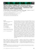
(b)
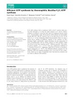
Figure 1: (a) FPGA board setup for demonstration; (b) prototype architecture.
Fingerprint
Binarization
(BINAR)
Binarized
Detection
(DETECT)
Possible
Direction
Generate maps
(MAPS)
Quality maps
Remove false
minutiae
Final minutiae
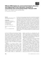
Figure 2: NIST minutiae extraction flow.
to the server. By doing this, the sensitive biometric data is
confined to the embedded device and the only information
transmitted is the final binar y result, which is nonsensitive.
The hardware platform to demonstrate our system con-
sists of a LEON-2 processor embedded in the Xilinx FPGA
(Virtex-II), DDR SDRAM, and an Authentec AF-2 CMOS
imaging fingerprint sensor. LEON-2 is a synthesizable VHDL
model of a 32-bit processor compliant with SPARC V8 archi-
tecture. The model is highly configurable, and particularly
suitable for system-on-chip (SOC) designs [15]. The demon-
stration setup and the architecture are shown in Figure 1.
The fingerprint sensor is connected via the serial link to the
FPGA board. The FPGA contains the soft LEON-2 SPARC
core and t wo acceleration units, one for minutiae processing
(DFT) and one for encryption purposes (AES).
To verify the fingerprint match algorithm, we apply our
system to a subset of the FVC2000 fingerpr int database [16].
In order to evaluate a realistic s ystem performance, we have
also constructed a new database using the Authentec AF-2
CMOS imaging sensor [17], which is a part of our finger-
print verification system. Ten live-scan fingerprint samples
per finger from 10 different thumbs are captured, forming a
test bench having a total of 100 fingerprint images.
4. FEATURE EXTRACTION
The feature-extraction step is the most computation-
intensive step. Its optimization to fit on an embedded device
consists of several steps. The first step is the optimization of
the algorithm itself to reduce the number of operations. The
second step consists of identifying the computation bottle-
necks and designing acceleration units for it. The third step
consists of the memory optimization.
4.1. Minutiae extraction algorithm
The start point of the algorithm for extracting the minutiae
of a fingerprint is taken from the NIST Fingerprint Image
Software [18]. The basic steps are shown in Figure 2.
The fundamental step in the minutiae extraction pro-
cess is deriving a directional ridge fl ow map to represent the
orientation of the ridge structure (MAPS). To locally analyze
4 EURASIP Journal on Applied Signal Processing
Window
(24
× 24 pixel)
15.
−78.75
◦
14. −67.5
◦
13. −56.25
◦
12. −45
◦
11. −33.75
◦
10. −22.5
◦
9. −11.25
◦
8. 0
◦
7. 11.25
◦
6. 22.5
◦
5. 33.75
◦
4. 45
◦
3. 56.25
◦
2. 67.5
◦
1. 78.75
◦
0. 90
◦
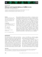
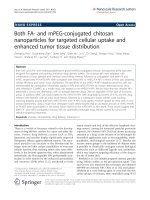
Figure 3: An example case of the window rotation.
the fingerprint, the image is divided into a grid of 8 × 8 pixel
blocks with a larger surrounding 24
× 24 pixel window. For
each block, the surrounding window is rotated incrementally
and a discrete fourier Transform (DFT) analysis is conducted
at each orientation. The number of orientations is set to 16.
Within an orientation, the pixels along each rotated row of
the window are summed together, forming 16 vectors of row
sums (see Figure 3). Each vector of row sums is convolved
with 4 waveforms of increasing frequencies, producing reso-
nance coefficients that represent how well the vector fits the
specific waveform. The dominant ridge flow direction for the
block is determined by the orientation with the maximum
waveform resonance. Also the image quality is analyzed. The
blocks, for which it is difficult to accurately determine the
ridge flow, are marked, indicating that the minutiae detected
within those blocks are less reliable.
Each pixel is assigned a binary value based on the ridge
flow direction associated with the block to which the pixel
belongs(BINAR).A7
× 9 pixel grid is defined centered at the
pixel. The angle of the grid row is set parallel to the local ridge
flow direction. Then the center row sum and the average row
sum a re compared. If the center row sum is less than the av-
erage intensity, the center pixel is set to black; otherwise, it
is set to white. Following the binarization, the detection step
methodically scans the binary image of a fingerprint, identi-
fying the localized pixel patterns that indicate the ending or
bifurcation of a ridge (DETECT). Since the scanning tech-
nique is conservative to minimize the chance of missing true
minutiae, the minutiae candidates pointed out by perform-
ing these steps need further refinement stages. Typical types
of sources for the false minutiae include: (1) islands, lakes,
and holes in the binarized image; (2) nonreliable minutiae
in regions of poor image quality ; (3) side minutiae, hooks,
overlaps, minutiae that are too wide, and so forth. Consid-
ering these problems, several steps are performed to remove
the false minutiae from the candidates list.
4.2. High-speed accelerator
Implementing the fingerprint verification module on an em-
bedded device requires not only accuracy, but also high-
speed and low power consumption. In this paper, we investi-
gate both software and hardware optimization techniques to
achieve this goal.
Software optimization aims at reducing the cycle count
of the whole process. To get better performance, the first step
is to find out the bottlenecks of the system. For this purpose,
the TSIM SPARC simulator is used to profile the C code [15].
Simulation shows that the minutiae extraction process takes
most (
∼ 99%) of the execution time. Therefore, we will fo-
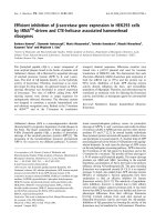
cus on the speed optimization of this module. Figure 4(a)
shows the profiling result of the minutiae extraction pro-
cess. The execution time of the image binarization and the
minutiae detection are 11% and 12% of the total, respec-
tively, and they are not considered the system bottlenecks.
However, the direction map deriving step (MAPS) occupies
74% of the total execution time. Therefore, the detailed al-
gorithm for it is investigated further. Figure 4(b) shows the
instruction-level profiling of the MAPS. The numbers of in-
structions for multiply (Mult) and addition (Add) sum up
to 56% of the total MAPS processing due to the repetitive
DFT calculations for creating the direction map. Based on
Shenglin Yang et al. 5
Others
3%
BINAR
11%
DETECT
12%
MAPS
74%
(a)
Others
8%
Store
4%
Logical
9%
Branch
8%
Load
15%
Add
15%
Mult
41%
(b)
Figure 4: (a) Profiling of the execution time for the minutiae ex-
traction; (b) instruction-level profiling of MAPS.
the profiling results, software optimization and hardware ac-
celeration are considered for the DFT calculations in the di-
rectional map-deriving step.
(1) Software optimization for the minutiae extraction
Observing the directional map of a fingerprint, we find that
the neighboring blocks tend to have similar directions due to
the continuousness of the ridge flow. An example is shown in
Figure 5. This characteristic can be used to significantly re-
duce the number of DFT calculations. For instance, the first
direction data, upper left in Figure 5, is calculated using the
same method as the original approach. After that, when de-
ciding the direction of the block right next to it, instead of
beginning with θ
= 0, the DFTs for θ = 4, 5, 6 are first cal-
culated because the result is most likely to be θ
= 5. Gen-
erally, for each θ, the pixels along each rotated row of the
window are summed together forming a vector of 24 row
sums (row sum(i, θ), i
= 0, 1, 2, , 23). Each vector of row
sums is convolved with several waveforms. Discrete values for
the sine and cosine functions at different frequencies (ϕ)are
computed for each unit along the vector. The row sums in
a vector are then multiplied to their corresponding discrete
sine values, and the results are accumulated and squared.
The same computation is done between the row sums in
the vector and their corresponding discrete cosine values.
Figure 5: Example of direction map. “−1” means no direction be-
cause of the zero-padding in the image.
The squared sine component is then added to the squared co-
sine component, producing a resonance coefficient that rep-
resents how well the vector fits the specific waveform. The
resonance coefficient is described as
E
Total
(θ) =
ϕ
A
2
(ϕ, θ)+B
2
(ϕ, θ)
,
A(ϕ, θ)
=
23
i=0
row sum(i, θ) • sin
ϕ
· i · π
16
,
B(ϕ, θ)
=
23
i=0
row sum(i, θ) • cos
ϕ
· i · π
16
.
(1)
For instance, if for θ
= 5 the total energy is greater than
both its neighbors (θ
= 4, 6) as well as a threshold value
(E
TH
), the direction of θ = 5 is considered correct. Other-
wise, θ is incremented or decremented until the total energy
for it peaks with a value greater than E
TH
.Inotherwords,if
the three conditions in (2) are met, the direction of a block
is determined. It is noted that the sine and cosine values are
left-shifted by 16 bits for fixed-point refinement. The execu-
tion speed as well as the matching error rate is measured
when E
TH
is changed from 1.0 × 10
7
to 3.5 × 10
7
.Theexper-
imental result shows that when E
TH
is larger than 2.0 × 10
7
,
the error rate is within an acceptable range:
E
Total
(θ) >E
Total
(θ − 1) [when θ = 0, θ − 1 = 15],
E
Total
(θ) >E
Total
(θ +1) [whenθ = 15, θ +1= 0],
E
Total
(θ) >E
TH
.
(2)
(2) DFT accelerator for the minutiae extraction
Software optimizations reduce the number of DFT calcu-
lations and result in a significant speedup of the minutiae
extraction process. However, there are still a large number
of DFT calculations, even if E
TH
is set to a proper value.
Therefore, DFT hardware acceleration is needed in addition
to software optimization. A DFT coprocessor is designed to
6 EURASIP Journal on Applied Signal Processing
AMBA peripheral bus
Data Address Control signal
DFT accelerator
Memory mapped I/F
Controller
DFT (k
= 1) DFT (k = 2) DFT (k = 3) DFT (k = 4)
32-bit data bus
Figure 6: Block diagram for the memory-mapped DFT accelerator.
implement four parallel one-dimensional 24-point DFTs on
four different discrete sample frequencies (see Figure 6).
The coprocessor is memory-mapped and two memory
locations are used between the CPU and the coprocessor for
the inst ructions and the data, respectively. The 16 row sum
vectors are sent to the coprocessor and the sine and cosine
accumulate results are retrie ved. By performing this, the con-
trol flow and the data flow of the DFT algorithm are sep-
arated into the embedded LEON-2 processor and the DFT
coprocessor, respectively [19]. This coprocessor design has
been done with the design environment GEZEL [20]. With
the GEZEL environment, a cosimulation is setup between
the software running on the embedded core and the hard-
ware acceleration units. GEZEL facilitates the codevelopment
of hardware accelerator units and software optimization on
the embedded platform. The area cost for the DFT copro-
cessor is 2844 LUTs and whole system requires 7700 LUTs
after place and route. The energy calculation part is not in-
cluded because it needs a square operation of 16-bit data,
which requires a gener a l multiplier. As a result, the execution
time of the minutiae extraction is reduced to about 4 seconds
from originally 9 seconds resulting from the fixed-point im-
plementation on the 50 MHz LEON-2 processor, as shown in
Figure 7(a). This system speed is among the top results in the
light category of FVC2004 [21]. In the meantime, the energy
consumption is reduced from 5.187 mJ to 2.500 mJ in case of
E
TH
= 2.7 × 10
7
as presented in Figure 7(b). In order to ob-
tain the energy estimation, the power is simulated using Xil-
inx’s Xpower and we get the total system cycle number from
cycle true simulation with GEZEL.
5. MEMORY OPTIMIZATION
As mentioned before, in a fingerprint verification system, the
major computational bottleneck is the fingerprint minutiae
extraction. Like many other image processing algorithms,
it is array-dominated. Therefore, apart from optimizations
SW opt.+HW acc.S/W opt.+HW acc.Org.
(Fixed point)
E
TH
= 27 M E
TH
= 10 M
0
1
2
3
4
5
6
7
8
9
10
Execution time (s)
OTHERS
MAPS
DETECT
BINAR
(a)
H/W acc.S/W opt.Org.
1
2
3
4
5
6
Energy consumption (mJ)
(b)
Figure 7: (a) Reduction of the execution time for the minutiae ex-
traction; (b) reduction of the energy consumption for the minutiae
extraction (E
TH
= 2.7 × 10
7
).
for high-speed calculation, memory management is also
necessary. In this section, we will int roduce a memory analy-
sis method. Several memory optimization techniques are im-
plemented based on the analysis results.
5.1. Memory analysis methodology
When a program is running, the memory space is divided
into two parts: a program segment and a data segment. The
data seg ment includes a heap and a stack. The heap starts
from the bottom of the program segment and increases when
the latest reserved memory block is beyond its range. When-
ever there is dynamic memory allocation, a block of memory
is reserved for later use. When a memory free happens, the
specific memory block is returned to the memory pool. On
the other hand, the stack pointer position changes when a
function call is executed or returned. Generally, the stack and
the heap grow and shrink in opposite direction. A collision
Shenglin Yang et al. 7
Program segment
Heap
Heap bottom
Stack pointer
Stack
Data segment
Figure 8: Memor y partitioning during the program running time.
of the stack and the heap implies a fatal error state. At any
particular moment, the memory usage of the system is deter-
mined by the sum of the size of the program, the heap, and
the stack as shown in Figure 8.
By inserting the memory trace agents in the program
where memory usage changes can happen, we get the posi-
tion of the heap bottom and the stack pointer dynamically
during the progra m run time. Taking the program size into
consideration, a dynamic memory usage trace map is gener-
ated. From the trace map, we can get information about the
dynamic memory requirement as well as the memory bottle-
neck of the application.
5.2. Baseline result for the minutiae detection
Applying the methodology described in the previous sec-
tion to the baseline minutiae extraction algorithm, a mem-
ory trace map is obtained (see Figure 9(a), where the x-
axis shows the number of memory change points). The
peak memory usage of the system is 1.572 Kbytes, including
325 Kbytes of program segment memory and 1.247 Kbytes
of data segment memory. For most portable embedded sys-
tems, a memory size beyond 1 Mbytes is too expensive. In or-
der to reduce the memory requirement for this application,
we try to minimize the program size as well as the running
time memory usage based on the information obtained from
the memory trace map.
5.3. Memory optimization
(1) Architecture optimization
The NIST starting point program, as is the case for most fin-
gerprint extraction algorithms, is floating-point based, while
the LEON-2 processor, as most low power embedded pro-
cessor cores, only supports fixed-point computation. There-
fore, we perform a fixed-point refinement optimization by
replacing all the floating-point variables with 32-bit long in-
teger ones. From the memory trace map (see Figure 9(b)) of
the fixed-point refined program, we notice that both the pro-
gram segment size and data segment size decrease. This is be-
cause, on the one hand, the fixed-point refinement removes
the floating-point calculation-related libraries; on the other
hand, the size of the elements of most arrays are modified
from the 8-byte “double” type to the 4-byte “int” type, which
reduces the storage memory by half. In total, the memory re-
quirement for a fixed-point refined program is 1.267 Kbytes.
(2) In-place optimization
The memory trace maps in Figures 9(a) and 9(b) show that
there is a major jump which introduces most of the mem-
ory usage in a very short period. Our idea for reducing the
data segment memory is first finding out where the jump
happens, then analyzing the algorithm to figure out the rea-
son for the major memory usage and implementing memory
management techniques to remove or lower the jump.
Detailed investigation of the minutiae extraction algo-
rithm shows that the biggest jump happens when a routine
named “pixelize
map” is called. The functionality of this rou-
tine is to convert the block-based maps for direction, low-
flow flag, and high-curve flag into pixel-based ones. For each
pixelized map, 262.144 (256
× 256 × 4) bytes of memory are
required since for each pixel, one 32-bit integer is used to
present each value. This results in the jump in the memory
trace map.
The dimensions for the three maps are exactly the same.
Moreover, the values in direction
map vary from 0 to 32 and
low
flow map and high curve map consist of only 0 and 1.
Therefore taking one corresponding element from each map,
only 6 bits are required per pixel (4 bits for direction
map,
1bit for low
flow map, and 1 bit for high curve map). It
is possible to merge these three different m aps into one
map since we can combine the three elements (one from
each map) in one 32-bit integer. In compiler terminology,
this operation is called loop merging [ 22]. By implementing
this compression, the peak memory requirement becomes
744 Kbytes (see Figure 9(c)). The data segment memory de-
creases by 590 Kbytes compared to the previous result, while
the program segment size slightly increases by 47 Kbytes due
to the additional calculations, which are needed for the com-
pression and decompression of the pixelized maps.
(3) Online calculation
As shown in Figure 9(c), the memory requirement bottle-
neck is still in the pixelize
map routine. Further optimiza-
tion can be implemented by reordering the sequence of cal-
culations [22]. Instead of generating the complete pixelized
maps, storing them and then using them, we adopt a run-
ning time calculation for the map value of each pixel. It is a
form of “just-in-time” calculations: a map element is gen-
erated by the program only when it is referred to during
run time. This technique removes the major memory usage
jump in the memory trace map, but it does require an anal-
ysis of the relative creation time and consumption time of
the map values. A minimum memory size is obtained when
the creation is just before the consumption [23]. The draw-
back of it is that the pixel index needs to be calculated each
time it is referred. However, using this online calculation, the
time consuming routine for generating the pixelized maps is
8 EURASIP Journal on Applied Signal Processing
12108642
×10
5
0
0.4
0.8
1.2
1.6
Memory usage (Mbytes)
(a)
543210
×10
5
0.4
0.8
1.2
Memory usage (Mbytes)
(b)
54321
×10
5
0
0.2
0.4
0.6
Memory usage (Mbytes)
(c)
54321
×10
5
0
0.1
0.2
0.3
0.4
0.5
Memory usage (Mbytes)
(d)
Figure 9: Memory trace maps for (a) baseline program, (b) architecture optimization, (c) in-place optimized, (d) online calculation.
skipped, thus it is found that this technique will save memory
with no cost of speed. The result of this method is shown as
Figure 9(d). Comparison of the results shows that both the
program segment size and the data segment size decrease.
The total memory requirement is 483 Kbytes, which outper-
forms all the algorithms in the light category of FVC2004
[21]. Figure 10 shows the memory reduction for the opti-
mization techniques introduced before.
6. MATCHING
The matching step compares the candidate fingerprint
against the stored template. It uses the minutiae obtained
from the previous steps to perform this comparison. A novel
more secure matching algorithm is proposed in our sys-
tem. Unlike most of the existing techniques, this algorithm
is only based on the local neighborhood structure of the
fingerprint minutiae. There are two main reasons we pro-
posed this matching technique. First, a pure local structure
does not rely on any global information; therefore no cal-
culation is needed for alignment. This makes the algorithm
very efficient in terms of speed. Secondly, this algorithm w ill
increase the system security since the global picture of the
fingerprint cannot be easily obtained even when the stored
templates are disclosed.
6.1. Algorithm
From the result of the minutiae extr action step, information
such as the x, y coordinates and the local ridge direction is
available for each minutia. As mentioned before, direct stor-
age of the minutiae set could lead to disclosure of the biomet-
ric information. To enhance the security of the system, our
newly proposed technique is based on a derived local struc-
ture. Generally, given one minutia M, we define a new local
structure of it which is described as a feature vector:
L
M
=
d
1
, d
2
, , d
N
, ϕ
1
, ϕ
2
, , ϕ
N
, ϑ
1
, ϑ
2
, , ϑ
N
, Ψ
,(3)
where N is the number of neighbors taken into considera-
tion during matching. Ψ is the local ridge direction of the
minutia M
· d
n
(n = 1, 2, , N) describes the distance be-
tween the selected minutia M and its nth nearest neighbor,
ϕ
n
(n = 1, 2, , N) is the related radial angle between M and
its nth nearest neighbor, and θ
n
(n = 1, 2, , N) represents
Shenglin Yang et al. 9
On-line
calculation
In-place
optimization
Architecture
optimization
Baseline
0
2
4
6
8
10
12
×10
2
Kbytes
Text segment
Data segment
Figure 10: Memor y-reduction techniques for minutiae extraction.
the related position angle of the nth nearest neighbor. One
example for N
= 2 is shown in Figure 11, descr ibing the lo-
cal structure of a minutia with its two nearest neighbors. All
the elements in the local structure can be calculated from the
information obtained from the minutiae extraction follow-
ing (4):
d
n
=
(x
n
− x
0
)
2
+(y
n
− x
0
)
2
,
ϕ
n
= diff
Ψ
n
, Ψ
,
ϑ
n
= diff
arctan
y
n
− y
0
x
n
− x
0
, Ψ
, n = 1, 2, , N.
(4)
The function diff(
·) calculates the difference of two an-
gles and ports the result to the range [0, 2π). When two
minutiae are compared, the relative position and angles of
their N nearest neighbor minutiae are examined. We can
rewrite (3) to obtain an alternative form of the local feature
vector. Assume one minutia M in the input fingerprint is
L
M
=
d
1
, ϕ
1
, ϑ
1
,
d
2
, ϕ
2
, ϑ
2
, ,
d
N
, ϕ
N
, ϑ
N
, Ψ
(5)
and one minutia M
in the stored template is
L
M
=
d
1
, ϕ
1
, ϑ
1
,
d
2
, ϕ
2
, ϑ
2
, ,
d
N
, ϕ
N
, ϑ
N
, Ψ
. (6)
The proposed matching algorithm calculates how similar
the neighborhood of one minutia in the input fingerprint is
to that of one in the stored template. If it is similar enough,
these two minutiae are taken as a “matched” minutiae pair.
After each minutia pair is compared, the total number of
“matched” minutiae pairs is used to calculate the final match-
ing score.
To decide whether or not M and M
are a matched
minutiae pair, a small four-dimensional range box is set for
(d, ϕ, ϑ, Ψ), respectively:
{Δ
d
, Δ
ϕ
, Δ
ϑ
, Δ
Ψ
}. The first step is
to check the local ridge directions of the two minutiae. If
|Ψ − Ψ
| > Δ
Ψ
, M and M
are not matched. Therefore the
d
1
d
2
θ
1
θ
2
ϕ
1
ϕ
2
Figure 11: Local structure of a minutia (N = 2).
matcher searches for another minutiae pair. Otherwise, the
matcher continues to investigate the neighbor minutiae ac-
cording to the neighborhood condition described in (7):
d
i
− d
j
⇐=
Δ
d
,
ϕ
i
− ϕ
j
⇐=
Δ
ϕ
,
ϑ
i
− ϑ
j
⇐=
Δ
ϑ
.
(7)
If the conditions in ( 7) are all satisfied, the ith neighbor
of the input minutia M and the jth neighbor of the template
minutia M
are considered “marked.” After a thorough check
of all the neighbor minutiae of M and M
, the number of
marked neighbor pairs is accumulated as A. If this number
is above a specific threshold TH
A
, the minutiae M and M
are considered as a matched minutiae pair. The threshold is
set according to experimental results, which we will discuss
later. Following this procedure, a comparison of all the minu-
tiae in the input and template fingerprints results in the to-
tal number of matched minutiae pairs, B. Assuming that the
numbers of the minutiae of input and template fingerprints
are NUM
input
and NUM
temp
, respectively, the final matching
score is calculated as
score
=
B
max
NUM
input
,NUM
temp
. (8)
Two fingerprints will be verified as from the same finger if
their matching score is higher than a certain threshold.
According to the descriptions of the matching algorithm,
the template, which is stored in the embedded device, con-
sists only of the local relationship between each minutia and
its neighbors. Unlike other minutiae-based fingerprint ver-
ification systems, there is no global information about the
whole fingerprint stored. Therefore, even if the stored tem-
plate is compromised, it cannot be used to reconstruct the
original minutiae set of the fingerprint.
6.2. Definition of neighborhood structure
Our proposed matching method is based on the local struc-
ture of the minutiae. The selection of the number of neigh-
bors is very important for the system performance. If the
number is too small, which indicates a relative loose match-
ing condition, some nonmatched minutiae pairs, which are
somehow similar, are very likely to satisfy the matching con-
ditions. This may lead to a high false accept rate (FAR). On
10 EURASIP Journal on Applied Signal Processing
Table 1: Possibility to achieve baseline accuracy for different local-
structure definitions and thresholds.
Number of neighbors in local structure
456 7
Thresholds
(TH
A
)
2 No No No No
3 No Yes Yes No
4 —NoNo No
5 ——No No
6 ——— No
the contrary, if the neighbor number is set too large, the
matching condition becomes very strict. Many matched pairs
may fail because the fingerprint image is sometimes incom-
plete and the minutiae detection is not very precise. This may
result in a high false reject rate (FRR). In order to choose
the proper neighborhood struc ture which could achieve rea-
sonable FRR and FAR, experiments are performed for differ-
ent local structure definitions, where the number of neighbor
minutiae taken into account varies from 4 to 7. For each local
structure definition, matching accuracy for different marked
neighbor pair thresholds is investigated. In this work we use
1% FRR and 0.01% FAR as the baseline accuracy needed for
modern biometric systems [24], Table 1 presents the possi-
bility to reach this standard for different cases.
From Ta ble 1 it is found that the matching algorithm
based on minutiae structure including 5 or 6 neighbors can
achieve desirable accuracy with the mar ked pair threshold of
3. Further results are shown in Figure 12 for these two cases.
The x-axis is the FRR and the y-axis shows the FAR. After
analyzing the result, we define the number of neighbors as
6 and the marked neighbor pair threshold TH
A
is set to 3 in
our work. By selecting this local structure, we achieve an FRR
of 1% and an FAR of less than 0.1%.
1
Also we compared the template size of our matching al-
gorithm with others. For a typical case, 0
≤ d
i
≤ 256,
0
≤ ϕ
i
, θ
i
, Ψ ≤ 32, the average template size for our algorithm
is around 0.5 kbytes, which is comparable to the template size
in the light category of FVC2004 [21].
7. CONCLUSION
In this article, we demonstrate that it is feasible and it can
be done to implement a complete fingerprint authentication
system on a 50 MHz embedded platform. To address the se-
curity problem for biometric authentication systems, we pro-
pose a novel secure fingerprint verification technique, within
which the matching algorithm is based on a well-defined lo-
cal neighborhood structure of the minutiae.
In order to speed up the fingerprint image processing, a
set of software and hardware optimizations methods are ap-
plied, gaining a 65% execution time reduction with less than
half the energy consumption. A memory analysis method is
1
In the simulation of our database, there is no false accept error.
0.030.0250.020.0150.010.0050
FRR
0.5
1
1.5
2
2.5
3
×10
−4
FAR
Baseline range
NUM
neighbor
= 5, TH
A
= 3
NUM
neighbor
= 6, TH
A
= 3
Figure 12: False reject rate (FRR) and false accept rate (FAR) for
different selections of local structure.
introduced to trace the program memory usage during run
time. Based on the analysis results, memory-optimization
techniques and code transformations are implemented and
67% memory storage requirement reduction is achieved.
This results in an implementation that ranks in the top of the
light category, with an execution time of less than 4 seconds
on 50 MHz platform, an energy estimate on an FPGA of
2500 mJ, and a memory size, which is the smallest in the light
category of FVC2004. This work successfully ports the com-
plete fingerprint processing, which is usually done on a cen-
tral server, to a resource constraint embedded device.
ACKNOWLEDGMENTS
This work was supported by the NSF, account no. CCR-
0098361, the Langlois Foundation, and UC MICRO. The
authors would like to thank all the teammates in the Thumb-
Pod project [25, 26]. We also thank Gaisler Research for pro-
viding the LEON-2 SPARC core and for support in setting up
the simulation environment [15].
REFERENCES
[1] Y. Gil, D. Moon, S. Pan, and Y. Chung, “Fingerprint verifi-
cation system involving smart card,” in Proceedings of the In-
ternational Conference on Information Security and Cryptol-
ogy, vol. 2587 of LNCS, pp. 510–524, Seoul, Korea, November
2003.
[2] S. Prabhakar, S. Pankanti, and A . K. Jain, “Biometric recogni-
tion: security and privacy concerns,” IEEE Security and Privacy
Magazine, vol. 1, no. 2, pp. 33–42, 2003.
[3] V. Raghunathan, C . Schurgers, S. Park, and M. B. Srivastava,
“Energy-aware wireless microsensor networks,” IEEE Signal
Processing Magazine, vol. 19, no. 2, pp. 40–50, 2002.
[4] A. K. Hrechak and J. A. Mchugh, “Automated fingerprint
recognition using structural matching,” Pattern Recognition,
vol. 23, no. 8, pp. 893–904, 1990.
Shenglin Yang et al. 11
[5] A. Jain, L. Hong, and R. Bolle, “On-line fingerprint verifica-
tion,” IEEE Transactions on Pattern Analysis and Machine In-
telligence, vol. 19, no. 4, pp. 302–314, 1997.
[6] X. Jiang and W Y. Yau, “Fingerprint minutiae matching based
on the local and global structures,” in Proceedings of the In-
ternational Conference on Pattern Recognition, pp. 6038–6041,
Barcelona, Spain, September 2000.
[7] S. Yang, K. Sakiyama, and I. Verbauwhede, “A compact and ef-
ficient fingerprint verification system for secure embedded de-
vices,” in Proceedings of the 37th Asilomar Conference on Signal
Systems, and Computers, pp. 2058–2062, Pacific Grove, Calif,
USA, November 2003.
[8] A. Wahab, S. H. Chin, and E. C. Tan, “Novel approach to auto-
mated fingerprint recognition,” IEE Proceedings - Vision, Image
and Signal Processing, vol. 145, no. 3, pp. 160–166, 1998.
[9] P. Panda, F. Catthoor, N. Dutt, et al., “Data and memory op-
timization techniques for embedded systems,” ACM Transac-
tions on Design Automation of Electronic Systems, vol. 6, no. 2,
pp. 149–206, 2001.
[10] I. Verbauwhede, F. Catthoor, J. Vandewalle, and H. De Man,
“Background memory management for the synthesis of alge-
braic algorithms on multi-processor DSP chips,” in Proceed-
ings of the International Conference on VLSI (VLSI ’89),pp.
209–218, Munich, Germany, August 1989.
[11] I. Verbauwhede, C. Scheers, and J. Rabaey, “Memory esti-
mation for high level synthesis,” in Proceedings of the 31st
ACM/IEEE Design Automation Conference, pp. 143–148, San
Diego, Calif, USA, June 1994.
[12] P. Grun, F. Balasa, and N. Dutt, “Memory size estimation for
multimedia applications,” in Proceedings of the 6th Interna-
tional Workshop on Hardware/Software Codesign, pp. 145–149,
Seattle, Wash, USA, March 1998.
[13] Y. Zhao and S. Malik, “Exact memory size estimation for ar-
ray computations without loop unrolling,” in Proceedings of
the 36th ACM/IEEE Design Automation Conference, pp. 811–
816, New Orleans, La, USA, June 1999.
[14] P. Gupta, S. Ravi, A. Raghunathan, and N. K. Jha, “Efficient
fingerprint-based user authentication for embedded systems,”
in Proceedings of Design Automation Conference, pp. 228–233,
Anaheim, Calif, USA, June 2005.
[15] .
[16] FVC2000: The First International Fingerprint Verification
Competition, />[17] .
[18] M. D. Garr is, C. I. Watson, R. M. McCabe, and C. L. Wilson,
“User’s Guide to NIST Fingerprint Image Software (NFIS),”
NISTIR 6813, National Institute of Standards and Technology.
[19] P. Schaumont, K. Sakiyama, A. Hodjat, and I. Verbauwhede,
“Embedded software integration for coarse-gr ain reconfig-
urable architectures,” in IEEE 18th International Parallel and
Distributed Processing Symposium (IPDPS ’04), pp. 137–142,
Santa Fe, NM, USA, April 2004.
[20] P. Schaumont and I. Verbauwhede, “Interactive cosimulation
with partial evaluation,” in Proceedings of Design Automation
and Test in Europe (DATE ’04), pp. 642–647, Paris, France,
February 2004.
[21] FVC2004: The Third International Fingerprint Verification
Competition, />[22] K. Danckaert, F. Catthoor, and H. De Man, “A loop transfor-
mation approach for combined parallelization and data trans-
fer and storage,” in Proceedings of International Conference on
Parallel and Distributed Processing Techniques and Applications
(PDPTA ’00), vol. 5, pp. 2591–2597, Las Vegas, Nev, USA, June
2000.
[23] F. Catthoor, K. Danckaert, S. Wuytack, and N. D. Dutt, “Code
transformations for data transfer and storage exploration pre-
processing in multimedia processors,” IEEE Design & Test of
Computers, vol. 18, no. 3, pp. 70–82, 2001.
[24] R. J. Anderson, Security Engineering, A Guide to Building De-
pendable Distributed Systems, chapter 13, John Wiley & Sons,
New York, NY, USA, 2001.
[25] .
[26] D. Hwang, P. Schaumont, Y. Fan, et al., “Design flow for
HW/SW acceleration transparency in the ThumbPod secure
embedded system,” in Proceedings of the 40th ACM/IEEE De-
sign Automation Conference, pp. 60–65, Anaheim, Calif, USA,
June 2003.
Shenglin Yang received her B.S. and M.S.
degrees in electronics from Beijing Univer-
sity, Beijing, China, in 1998 and 2001, re-
spectively. She is now pursuing her Ph.D.
degree in electrical engineering at Univer-
sity of California, Los Angles. Her research
interests include biometrics, pattern recog-
nition, embedded implementation, and se-
curity system design. She is currently work-
ing on the biometric authentication system
for embedded devices. She is a Student Member of IEEE.
Kazuo Sakiyama obtained the B.Eng. and
M.Eng. degrees in electrical engineering
from Osaka University, Japan, in 1994 and
1996, respectively. From 1996 to 2004, he
was with the Semiconductor and IC Divi-
sion of Hitachi, Ltd. (now Renesas Technol-
ogy Corp.). During this time, he received
the M.S. degree in electrical engineering
from the University of California, Los An-
geles. He is currently working on a Ph.D.
program at the Katholieke Universiteit Leuven, Belgium. His main
research interest is efficient and secure embedded system architec-
tures and design methodologies.
Ingrid Ve rbauwhede’s interests include cir-
cuits, processor architectures, and design
methodologies for real-time, embedded
systems for applications such as security,
cryptography, digital signal processing, and
wireless applications. She received the Elec-
trical Engineering degree in 1984 and the
Ph.D. degree in applied sciences from the
KULeuven, Leuven, Belgium, in 1991. She
was a Lecturer and Visiting Research En-
gineer at UC Berkeley from 1992 to 1994. From 1994 to 1998,
she was a Principal Engineer first with TCSI and then with At-
mel in Berkeley, Calif. She joined UCLA in 1998 as an Associate
Professor and the KULeuven in 2003. At UCLA she ran the EM-
SEC, embedded security group. At KULeuven she is Codirector
of the ESAT-COSIC research group. She was the General Chair of
the IEEE International Symposium on Low Power Electronic De-
vices (ISLPED) in 2003. She is or was a member of several pro-
gram committees, including DAC, ISSCC, DATE, CHES, ICASSP,
SIPS, ASAP. She is the Design Community Chair on the 42nd
and 43rd DAC Executive Community. She is a Senior Member of
IEEE.