Báo cáo hóa học: " Research Article Interface for Barge-in Free Spoken Dialogue System Based on Sound Field Reproduction and Microphone Array" pptx
Bạn đang xem bản rút gọn của tài liệu. Xem và tải ngay bản đầy đủ của tài liệu tại đây (2.39 MB, 13 trang )
Hindawi Publishing Corporation
EURASIP Journal on Advances in Signal Processing
Volume 2007, Article ID 57470, 13 pages
doi:10.1155/2007/57470
Research Article
Inter face for Barge-in Free Spoken Dialogue System Based on
Sound Field Reproduc tion and M icrophone Array
Shigeki Miyabe,
1
Yoichi Hinamoto,
2
Hiroshi Saruwatari,
1
Kiyohiro Shikano,
1
and Yosuke Tatekura
3
1
Graduate School of Information Science, Nara Institute of Science and Technology, Takayama-Cho 8916-5,
Ikoma-Shi, Nara 630-0192, Japan
2
Department of Control Engineering, Takuma National College of Technology, Takuma-Cho Koda 551, Mitoyo-Shi,
Kagawa 769-1192, Japan
3
Faculty of Engineering, Shizuoka University, Johoku 3-5-1, Hamamatsu-Shi, Shizuoka 432-8561, Japan
Received 1 May 2006; Revised 17 October 2006; Accepted 29 October 2006
Recommended by Aki Harma
A barge-in free spoken dialogue interface using sound field control and microphone array is proposed. In the conventional spoken
dialogue system using an acoustic echo canceller, it is indispensable to estimate a room transfer function, especially when the
transfer function is changed by various interferences. However, the estimation is difficultwhentheuserandthesystemspeak
simultaneously. To resolve the problem, we propose a sound field control technique to prevent the response sound from being
observed. Combined with a microphone array, the proposed method can achieve high elimination performance w ith no adaptive
process. The efficacy of the proposed interface is ascertained in the experiments on the basis of sound elimination and speech
recognition.
Copyright © 2007 Shigeki Miyabe et al. This is an open access article distributed under the Creative Commons Attribution License,
which permits unrestricted use, distribution, and reproduction in any medium, provided the original work is properly cited.
1. INTRODUCTION
For hands-free realization of smooth communication with a
spoken dialogue system, it should be guaranteed that a user’s
command utterance reaches the system clearly. However, a
user might inter rupt sound responses from the system and
utter a command, or he might start speaking before the ter-
mination of the sound responses from the system. In such
a situation, the sound given from the system to the user is
observed as an acoustic echo return at a microphone used
for acquisition of the user’s speech input, and degrades the
speech recognition performance in receiving the user’s input
command. Such a situation is referred to as barge-in [1].
Hereafter, the sound message outputted from the system is
called response sound.
Asasolutiontothisproblem,anacousticechocan-
celler is commonly used [2]. Since the echo return of the
response sound is a convolution of the known response
sound signal and a transfer function from a loudspeaker
to a microphone, we eliminate the echo return by esti-
mating the transfer function with an adaptive filter. Many
types of acoustic echo canceller have been proposed, such
as single-channel, stereophonic, beamformer-integrated, and
wave-synthesis-integrated typ es [3–6]. The room t ransfer
function is variable and fluctuates because of changes of
room conditions, such as the movement of people in the
room and changes in temperature [7]. Therefore, the adap-
tation must be continued even after its temporary conver-
gence. However, in the state of barge-in (this is also called
a “double-talk problem”), since user’s speech input is mixed
in the observed signal, the speech acts as noise to the esti-
mation and the estimation fails. In this case, the adaptation
process should be stopped by some type of double-talk de-
tection technique [8, 9]. Therefore, when the room transfer
function changes in the barge-in state, the elimination per-
formance degrades.
In order to achieve robustness, we propose a new inter-
face for a barge-in free spoken dialogue system that combines
multichannel sound field control and a microphone array. At
first, to prevent the response sound from being observed at
the microphone elements, we utilize the sound field repro-
duction technique via multiple loudspeakers and an inverse
filter of the room transfer functions [10]. The sound field
reproduction is generally used in a transaural system [11],
which presents a three-dimensional sound image to a user
at a fixed position. We apply this technique to the response
2 EURASIP Journal on Advances in Signal Processing
sound elimination by controling sound field around the mi-
crophone to be silent alongside the transaural reproduction
at user’s ears. In the next step, user’s speech is enhanced by
microphone array signal processing. By increasing the num-
bers of loudspeakers and microphone elements, the control
of the proposed method becomes robust against the fluctua-
tion of the room transfer functions. With sufficient numbers
of loudspeakers and microphones, the proposed method en-
ables us to eliminate the response sound with enough robust-
ness to sustain speech recognition accuracy.
Although the proposed method requires many loud-
speakers and the cost for the hardware is higher than the con-
ventional acoustic echo canceller, the proposed method uses
a fixed filter designed in advance and real-time a daptation is
unnecessary. As a result, computational cost can be reduced.
In addition, the proposed method has an advantage that
sound virtual reality [12] can be achieved with transaural
reproduction. Thus we can realize duplex telecommunica-
tion, for example, video conference, with telepresence as if
the users share the same space. Besides, we can apply the pro-
posed method for control of car navigation system by spo-
ken dialogue system. We can eliminate not only the response
sound of the car navigation but also music of car audio.
Moreover, in this case user’s position is limited and nowa-
days car interior has many loudspeakers wh ose positions are
fixed. Therefore the disadvantage of the proposed method,
that is, fix of the positions of the loudspeakers and the user,
is not problematic.
In Section 2, we describe the basic concept and problems
of the conventional acoustic echo canceller. In Section 3,we
describe the principle of the proposed interface. In Section 4,
an experimental comparison of response sound elimination
performances is carried out. In Section 5, the effectiveness
of the proposed method is validated in the speech recogni-
tion experiment. In Section 6, we assess the quality of the
response sound reproduced by the proposed method.
2. CONVENTIONAL ACOUSTIC ECHO CANCELLER
To eliminate the acoustic echo of the response sound, an
acoustic echo canceller is generally used. In this section, we
describe the basic principle of the acoustic echo canceller,
and indicate its weakness against the fluctuation of a room
transfer function.
2.1. Principle and problem of conventional
acoustic echo canceller
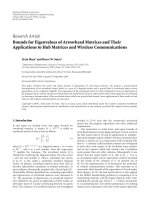
The configuration of an acoustic echo canceller using an
adaptive filter is shown in Figure 1. Let the source signal of
the response sound be x(ω), where ω shows the angular fre-
quency. The echo return of the response sound y
mic
(ω)can
be written as the product of x(ω) and the t ransfer function
g
mic
(ω) from a loudspeaker to a microphone,
y
mic
(ω) = g
mic
(ω)x(ω). (1)
The acoustic echo canceller calculates an estimate g
mic
(ω),
denoted as
g
mic
(ω). Then the estimated response sound
x(ω)
ε(ω)
Echo canceller
g
mic
(ω)
y
mic
(ω)
+
Loudspeaker
g
mic
(ω)
y
mic
(ω)
Microphone
User
Figure 1: Configuration of acoustic echo canceller in spoken dia-
logue system.
y
mic
(ω) can be obtained as
y
mic
(ω) = g
mic
(ω)x(ω). (2)
To e s t i m a te g
mic
(ω), an adaptive filter is used and the esti-
mated transfer function
g
mic
(ω) is updated iteratively to min-
imize the power of the error signal
(ω),
(ω) = y
mic
(ω) y
mic
(ω). (3)
Once the room transfer function is estimated, the acoustic
echo canceller can eliminate the response sound sufficiently.
However, whenever the transfer function is changed, it must
be reestimated. To follow the fluctuation of the transfer func-
tion in real time, online adaptation, for example, least mean
squares [13] or recursive least squares, is used. However,
these adaptation techniques are weak against noise. In the
state of barge-in, since user’s input speech is mixed with the
observed signal, an accurate error of the estimation cannot be
obtained and the adaptation diverges. Therefore, the adapta-
tion must be stopped using double-talk detection [8]. How-
ever, it is often difficult to decide whether the error is caused
by either fluctuation or barge-in.
2.2. Response sound elimination error of the
acoustic echo canceller when fluctuation
of the room transfer function occurs
The room transfer functions are easily changed with the vari-
ation of the system’s state such as the movement of people.
In this section, the response sound elimination error signal
(ω) is examined in the case w h ere the transfer function is
changed. Suppose that the variation Δg
mic
(ω) caused by the
fluctuation of room transfer functions is added to the origi-
nal transfer function g
mic
(ω). In this case, the response sound
is expressed as
y
mic
(ω) =
g
mic
(ω)+Δg
mic
(ω)
x( ω). (4)
The elimination error signal
(ω) of the response sound is
written using the estimated filter
g
mic
(ω)as
(ω) = Δg
mic
(ω)x(ω), (5)
where we assume that the filter was exactly estimated so as to
satisfy
g
mic
(ω) = g
mic
(ω)andg
mic
(ω)x(ω) g
mic
(ω)x(ω) = 0.
Shigeki Miyabe et al. 3
Response
sound
r(ω)
g
priR
(ω)
x
R
(ω)
g
priL
(ω)
x
L
(ω)
Inverse filter
h
1,K+1
(ω)
h
1,K+2
(ω)
.
.
.
h
M,K+1
(ω)
h
M,K+2
(ω)
S
1
.
.
.
S
M
g
N 1,1
(ω)
g
11
(ω)
g
K1
(ω)
g
KM
(ω)
g
K+1,M
(ω)
Array signal processing
(delay-and-sum array)
C
1
C
K
y
1
(ω), ,
y
K
(ω) = 0
C
K+1
C
K+2
Reproduced
sound
y
K+1
(ω)
y
K+2
(ω)
Silent
signal
y
mic
(ω) = 0
Figure 2: Configuration of the proposed system.
Since the acoustic echo canceller has no mechanism for im-
proving the robustness of the elimination (unless it contains
a suitable post-processing for that case), the fluctuation of
the transfer function effects directly its error. Therefore, if
the fluctuation occurs when the adaptation stops because of
barge-in, its elimination performance degrades.
3. PROPOSED METHOD: MULTIPLE-OUTPUT AND
MULTIPLE-NO-INPUT METHOD
In this section, we propose a new response sound elimina-
tion technique, which is robust against the fluctuation of
the room transfer function. The proposed method mainly
consists of two steps. First, sound field control with multi-
ple loudspeakers realizes silent zones at the microphone el-
ements while the dialogue system gives the response sound
to the user. Next, by delay-and-sum-ty pe signal process-
ing using a microphone array, the residual component of
the response sound caused by the fluctuation of the trans-
fer function is suppressed and user’s utterance is empha-
sized. The response sound signal is outputted from the mul-
tiple loudspeakers and cancelled at multiple control points.
With this mechanism, the response sound is prevented
from being inputted to the speech recognition system. Thus
we call this technique multiple-output/multiple-no-input
(MOMNI) method. We discuss the relation between the ro-
bustness of the control and the number of transfer chan-
nels. Then it is proved that we can improve its robustness
against the fluctuation of the transfer functions by increas-
ing the numbers of loudspeakers and microphone elements.
With sufficient numbers of loudspeakers and microphones,
the MOMNI method can eliminate the response sound with
enough robustness using fixed filter coefficients. Needless to
say, this processing requires no double-talk detection.
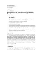
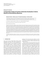
3.1. Sound field control
Here, we describe the sound field control used to eliminate
the acoustic echo of the response sound from the system. The
configuration of the proposed system is shown in Figure 2.
Let M be the number of secondar y sound sources S
1
, , S
M
and let N be the number of control points C
1
, , C
N
.The
control points C
1
, , C
K
(K = N 2) are arranged to the ele-
ments of a microphone array for acquisition of user’s speech,
and C
K+1
and C
K+2
are set at both ears of the user. The sig-
nals to be reproduced at the control points C
1
, , C
K+2
are
described by
x(ω)
=
x
mic 1
(ω), , x
mic K
(ω), x
R
(ω), x
L
(ω)
T
,(6)
and similarly, the sig nals observed at these control points are
represented by
y(ω)
=
y
mic 1
(ω), , y
mic K
(ω), y
R
(ω), y
L
(ω)
T
. (7)
Using, for example, chirp signal [14], we should measure in
advance all of the transfer functions from secondary sound
sources S
m
to control points C
n
,denotedbyg
nm
(ω), where
n
= 1, , N,andm = 1, , M. Here, to design an inverse
filter of the transfer functions with nonminimum phases, the
condition M>Nmust hold [10]. To use fixed filter coeffi-
cients for the inverse filter, the positions of the loudspeakers
and the microphones should not be changed after the mea-
surement. In addition, we specify the position for the user to
listen to the response sound, by, for example, setting a chair
at the position. Here in the phase of the measurement, to ob-
tain the transfer function of user’s ears, since it is a burden
for the user to sit on the position wearing microphones at
his/her ears, we can substitute the user by a head and torso
simulator (HATS) with microphones at the ears. Let G(ω)be
an N
M matrix consisting of g
nm
(ω), and let H(ω)bean
M
N inverse filter matrix with components h
mk
(ω). The in-
verse filter H(ω) is then designed so that
G(ω)H(ω)
= I
N
(ω), (8)
where I
N
(ω)denotesanN N identity matrix. Using the
transfer function matrix G(ω) and the inverse filter matrix
H(ω), the relation between the observed signals y(ω) and the
reproduced signals x(ω)iswrittenas
y(ω)
= G(ω)H(ω)x(ω). (9)
In (9), we reproduce the response sounds of a dialogue sys-
tematboththeuser’sears(i.e.,[y
R
(ω), y
L
(ω)] = [x
R
(ω),
x
L
(ω)]), and reproduce silent signals with zero amplitudes
at the microphone elements (i.e., [y
mic 1
(ω), , y
mic K
(ω)] =
[0, ,0])as
x(ω)
=
0, ,0
K
, x
R
(ω), x
L
(ω)
T
. (10)
By this sound reproduction, we can actualize a sound field in
which the response sound is presented to the user while the
response sound cancels at the microphone elements.
To remove the redundant filtering process of the zero
signals, we truncate the matrix H(ω) into H
(ω)whichis
an M
2 filter matrix composed of the filter components
h
mk
(ω)(m = 1, , M, k = K +1,K + 2) which are taken
from H(ω). By inputting the response sound to this filter ma-
trix, the following equation holds:
y(ω)
= G(ω)H (ω)
x
R
(ω), x
L
(ω)
T
=
0, ,0
K
, x
R
(ω), x
L
(ω)
T
.
(11)
4 EURASIP Journal on Advances in Signal Processing
Therefore, the condition equivalent to (10) can be realized
with an M
2 filter matrix.
Since the proposed method uses an inverse filter of the
room transfer function, we can show the response sound
to the user in the form of a transaural system, say, a three-
dimensional sound field localization [11]. In transaural sys-
tem, we can show the user a clear sound image of a pri-
mary sound source by reproducing a binaural sig nal [15],
say, a convolution of a signal and transfer functions from the
sound source to a person’s ears. To provide a practical ap-
plication of this property, we generate the response sound
signals x
R
(ω)andx
L
(ω) by multiplying a monaural source
of the response sound signal r
src
(ω) and the room transfer
functions g
pri
(ω) = [g
priR
(ω), g
priL
(ω)]
T
between a primary
sound source and both the user’s ears as
x
R
(ω), x
L
(ω)
T
= g
pri
(ω)r
src
(ω). (12)
In the transaural reproduction described above, the sound
image is degraded when the user is not at the prepared posi-
tion because the perceived response sound is not a n accurate
binaural sound. However, the sound quality away from the
prepared position is sufficient for the presentation of the re-
sponse sound for the spoken dialogue system. We will justify
this argument in the experiment in Section 6.
3.2. Signal processing using microphone array
In this section, we will focus our attention on array signal
processing. In this study, we adopt a delay-and-sum array sig-
nal processing [16] to emphasize the user’s utterance. The fil-
ter of the kth element in the delay-and-sum array is denoted
by w
k
(ω)fork = 1, , K. Then w
k
(ω) can be expressed as
w
k
(ω) =
1
K
e
jωτ
k
, (13)
where τ
k
stands for the arrival time difference of the user’s
utterance between a suitable standard point and the kth el-
ement position. We set τ
k
to form a directivity to the look
direction of the user. Suppose that the signal added through
the array filters is a signal for speech recognition. Then the
response sound contained in the observed signal is expressed
as
y
mic
(ω) =
K
k=1
w
k
(ω)y
mic k
(ω). (14)
When this delay-and-sum-ty pe ar ray is used, the system’s re-
sponse sounds which arrive from other than the target di-
rection are out of phase at each element, and only the user’s
speech which comes from the target direction is in phase at
each element and is added. As a result, only user’s speech can
be emphasized in the y
mic
(ω). Thus we give this signal to the
speech decoder to recognize the user’s speech.
3.3. Inverse system design for sound field reproduction
In a multipoint control system which controls multiple con-
trol points with many loudspeakers, large amounts of calcu-
lation and memory are needed to design an inverse filter in
the time domain. Therefore, we design the inverse filter ma-
trix H(ω) by using the least-norm solution (LNS) in the fre-
quency domain [12]. The method has advantages that the
amount of calculation is small in the frequency domain, and
the designed system is stable because the output from each
sound source is suppressed to the minimum. Here, we use
the Moore-Penrose generalized inverse mat rix as the inverse
matrix which gives the least-norm solution. We obtain a sin-
gular value decomposition of G(ω)as
G(ω)
= U(ω)
Γ
N
(ω), O
N,M N
(ω)
V
H
(ω),
Γ
N
(ω) diag
μ
1
(ω), μ
2
(ω), , μ
N
(ω)
,
(15)
where U(ω)andV(ω)areN
N and M M unitary matr ices,
respectively, μ
n
(ω)forn = 1, 2, , N are the singular values
of G(ω), and are arranged so that μ
n
(ω) μ
n+1
(ω)inmatrix
Γ
N
(ω), O
N,M N
(ω)denotesanN (M N) null matrix, and
H
(ω) represents a conjugate transposition.
Then the Moore-Penrose generalized inverse matrix
G
+
(ω)(= H(ω)) of G(ω)isgivenby
G
+
(ω) = V(ω)
Λ
N
(ω)
O
M N ,N
(ω)
U
H
(ω),
Λ
N
(ω) diag
1
μ
1
(ω)
,
1
μ
2
(ω)
, ,
1
μ
N
(ω)
.
(16)
Then we utilize the Moore-Penrose generalized inverse ma-
trix for the inverse filter as H(ω)
= G
+
(ω).
3.4. Response sound elimination error for fluctuation
of room transfer functions
In an acoustic echo canceller, because we need to reestimate
the transfer function when it is changed, there is a prob-
lem that the response sound elimination accuracy degrades
during the estimation process. In contrast, it is proved that
the proposed technique is robust against the fluctuation of
room transfer functions, even when the fixed filter coeffi-
cients are used. Here, we suppose that an inverse filter matrix
computed before the fluctuation is used to control the sound
field.
Supposing that the variation Δg
nm
(ω) caused by the fluc-
tuation of transfer functions is added to a transfer function
g
nm
(ω), the transfer function matrix after the fluctuation will
become G(ω)+ΔG(ω), where ΔG(ω)isanN
M matrix
composed of Δg
nm
(ω). Then, by using an inverse filter matrix
H(ω) designed before the fluctuation of transfer functions,
the signals y(ω) observed at each control point are expressed
as
y(ω)
=
G(ω)+ΔG(ω)
H(ω)x(ω)
=
I
N
(ω)+ΔG(ω)H(ω)
x(ω),
(17)
and the errors caused by the fluctuation are represented
as ΔG(ω)H(ω)x(ω). In this case, the error Δy
mic
(ω) of the
Shigeki Miyabe et al. 5
response sound elimination y
mic
(ω)in(14)iswrittenas
Δy
mic
(ω)
=
K
k=1
w
k
(ω)
M
m=1
Δg
(k+2)m
(ω)
h
m1
(ω)x
R
(ω)+h
m2
(ω)x
L
(ω)
.
(18)
Since this system controls y
mic
(ω) such that it is 0 before the
fluctuation of transfer functions, Δ y
mic
(ω) after the fluctua-
tion is the response sound elimination error signal
(ω). This
is expressed as
(ω) = y
mic
(ω)+Δ y
mic
(ω) = Δ y
mic
(ω). (19)
Next, let the singular values of G(ω)beμ
j
(ω)forj =
1, 2, , N and let the eigenvalues of G
H
(ω)G(ω)beλ
j
(ω)for
j
= 1, 2, , N. Then, the norm G(ω) is given by
G(ω)
=
max
j
λ
j
(ω)
=
max
j
μ
j
(ω)
2
=
μ
1
(ω)
,
(20)
where max
j
(a
j
) denotes the largest element of a
j
for any j.
The relation λ
j
(ω) = μ
j
(ω)
2
is used here.
Alternatively, since the singular values of G
+
(ω)aregiven
by 1/μ
j
(ω), the norm G
+
(ω) is expressed as
G
+
(ω)
=
max
j
1
λ
j
(ω)
=
max
j
1
μ
j
(ω)
2
=
1
μ
N
(ω)
.
(21)
Since the secondary sound source is arranged with almost
equal distance for each control point, if the number of sec-
ondary sound sources, M, increases, the norm of G(ω) is di-
rectly proportional to M, that is,
G(ω) M.Moreover,
the condition number of G(ω), which is expressed by the
ratio between the maximum and minimum singular values,
that is,
cond(G)
=
μ
1
μ
N
, (22)
is known to be close to unity when the number of secondary
sound sources arranged is much larger than that of control
points (this is experimentally proven in Section 4.3). There-
fore, the following relation can be derived from (20)and
(21):
H(ω)
=
G
+
(ω)
=
1
μ
N
(ω)
1
μ
1
(ω)
=
1
G(ω)
1
M
.
(23)
Substituting (13) into (18), we obtain
Δ
y
mic
(ω)
=
H(ω)
1
K
K
k=1
M
m=1
Δg
km
(ω)
h
m(K+1)
(ω)x
R
(ω)+h
m(K+2)
(ω)x
L
(ω)
e
jωτ
k
,
(24)
where
h
mn
(ω) = h
mn
(ω)/ H(ω) . We assume that Δg
nm
(ω)
for n
= 1, 2, , N and m = 1, 2, , M are mutually inde-
pendent and follow the same Gaussian distribution with zero
mean and variance σ
2
. Furthermore, since h
mn
(ω)isafunc-
tion normalized by
H(ω) and independent on M, the de-
viation of
in (24)canberepresentedbyη MKσ,where
η is a suitable constant. Therefore, the elimination error
(ω)
of response sound is obtained from (23)as
(ω) = Δy
mic
(ω)
1
M
1
K
MK =
1
MK
. (25)
In other words, (25) shows that the elimination error of
the response sound for the fluctuation of the transfer func-
tions is inversely proportional to
MK. Thus, if the num-
ber of transfer channels from loudspeakers to microphones
increases, the response sound elimination of the proposed
method improves its robustness against the fluctuation of the
transfer functions.
We remark that in the real environment, it is difficult to
prove whether or not the variations Δg
nm
(ω) caused by the
fluctuation of the room transfer functions are mutually in-
dependent for every channel from a loudspeaker to a micro-
phone. However, in the next section, the simulations using
impulse responses measured in the real environment show
that the error estimation in (25) is valid.
4. EXPERIMENTAL COMPARISON OF RESPONSE
SOUND ELIMINATION PERFORMANCE
To assess the robustness of the proposed method against
the fluctuation of the room transfer functions, the response
sound elimination performance of the proposed method is
evaluated by simulations. Its performance is compared with
that of conventional acoustic echo canceller.
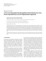
4.1. Experimental conditions
The simulations are carried out by using impulse responses
measured in a real acoustic environment. Figure 3 shows the
arrangement of the apparatuses. To imitate the user at the
center of the room, we set a HATS. To cause fluctuations of
the room transfer functions intentionally, we placed a life-
size mannequin as an interference near a user, under the as-
sumption that a person approaches to the user. We measured
in a total of 13 patterns of the room impulse responses: 12
patterns are for the state in which the interference is allo-
cated, and the remaining pattern is for the state in which no
6 EURASIP Journal on Advances in Signal Processing
interference exists. The transfer functions before fluctuation
are used to design filters for both the acoustic echo canceller
and the proposed method, and we evaluated the performance
under static transfer functions after fluctuations. To prevent
the effect of the change of condition to observe the user’s ut-
terance, we did not change the user’s position in these fluc-
tuations. A loudspeaker set in front of the user is used both
as an acoustic echo canceller and as a primary sound source
of the proposed method. The reverberation time is about 160
milliseconds. T he room impulse responses are sampled at a
frequency of 48 kHz and the magnitudes are quantized to 16
bits. We used a circular array with 12 elements, and equally
spaced elements were selected for use.
4.1.1. Conventional acoustic echo canceller
Our interest is focused on the robustness against the fluctua-
tion of room transfer functions. Therefore, the experiment is
carried out under the assumption that the filter coefficients
of the acoustic echo canceller are once estimated precisely,
and then the fluctuation occurs when the estimation stops
because of barge-in. To imitate this situation, we used the
transfer function before fluctuation as the estimated trans-
fer function of the acoustic echo canceller, and fixed its filter
coefficients. The microphone element closest to the user is
chosen as a microphone for acquisition of the user’s speech.
4.1.2. Proposed method
The inverse filter in the proposed method is calculated us-
ing only the impulse responses in the case wh ere there is no
fluctuation. The design conditions of the inverse filters are as
follows: the number of secondary sound sources M
= 4to
36, the number of control points N
= 3to8,thefilterlength
16384, and the passband range 150 to 4000 Hz.
4.2. Evaluation score
The response sound elimination performance is evaluated
using echo return loss enhancement ( ERLE) as
ERLE( dB)
= 10 log
10
ω
y
micref
(ω)
2
ω
(ω)
2
, (26)
where y
micref
(ω) is the response sound reproduced at a stan-
dard microphone, and
(ω) is the response sound elimina-
tion error signal derived from (5)or(19).
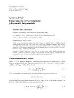
4.3. Experimental results and discussion
Figures 4–6 show that frequency characteristics of the re-
sponse sound elimination error signal in the conventional
acoustic echo canceller and proposed method after the room
transfer function have changed. In these evaluations, we used
a female utterance selected from the ASJ database [17]asa
response sound. From these figures, it turns out that the re-
sponse sound can be suppressed independent of frequency in
the passband by even w hich techniques.
Loudspeakers
for acoustic
echo canceller
Microphone
array
Loudspeakers
for sound field
control
Microphone to
observe response
sound
Position of
interference
135811
246
9
12
7
10
1m 0.5m
0.5m
3.9m
0.5m
Figure 3: Layout of acoustic experiment room.
The ERLE for each position of the interference in the
case of the typical number of loudspeakers and 2 elements
is shown in Figure 7, and that for each position of interfer-
ence in the case of 24 loudspeakers and the typical number
of microphones is in Figure 8. In these evaluations, to remove
the effect of the bias of frequency characteristics, we used a
white noise as a response sound. It can be seen that increas-
ing both the number of microphone elements and the num-
ber of loudspeakers improves the performance of the pro-
posed method, and c an make the control robust against the
fluctuation of room transfer functions. Regardless of the po-
sition of the interference, the performance of the proposed
method is superior to that of the conventional echo canceller.
Hereafter, we discuss only the averaged ERLE of 12 types of
fluctuations.
In Figure 9, ERLE is shown as a function of the number
of transfer channels (
= MK) from the loudspeakers to the
microphone elements. The theoretical curve in the figure is
drawn by plotting the ERLE derived from (25), which is given
by
ERLE
theory
(dB) = 10 log
10
ω
y
micref
(ω)
2
ω
(ω)
2
= 10 log
10
ω
y
mic
(ω)
2
ω
Δy
mic
(ω)
2
ξ +10log
10
1
1/(MK)
ξ +10log
10
(MK),
(27)
where ξ is a suitable constant.
From this figure, we can see that the response sound
elimination performance is improved if the number of trans-
fer channels increases. It also turns out that the deviation
between the experimental and theoretical values arises when
the number of microphone elements increases. The reasons
are as follows.
Shigeki Miyabe et al. 7
0 500 1000 1500 2000 2500 3000 3500 4000
100
80
60
40
20
0
20
40
Frequency (Hz)
Amplitude (dB)
Without processing
With processing
Figure 4: Example of frequency characteristics of observed signal
obtained by acoustic echo canceller. The signal is obser ved at the
microphone near the user. The position of interference is number 1
in Figure 3.
0 500 1000 1500 2000 2500 3000 3500 4000
100
80
60
40
20
0
20
40
Frequency (Hz)
Amplitude (dB)
Without processing
With processing
Figure 5: Example of frequency characteristics of observed signal
obtained by the proposed method with 36 loudspeakers and 1 mi-
crophone element. The signal is observed at the microphone near
the user. The position of interference is number 1 in Figure 3.
(A) The stability margin of the inverse filters b ecomes
small when the number of control points is close to that of
the secondary sound sources.
(B) When there exist too many transfer channels, the in-
dependence of each channel is no longer valid. Consequently,
the performance is saturated.
To prove the above claim (A), we show the condition
number of transfer functions in Figure 10. The condition
0 500 1000 1500 2000 2500 3000 3500 4000
100
80
60
40
20
0
20
40
Frequency (Hz)
Amplitude (dB)
Without processing
With processing
Figure 6: Example of frequency characteristics of observed sig-
nal obtained by proposed method with 36 loudspeakers and 6
microphone elements. The signal is observed at the microphone
near the user. The position of interference is number 1 in Figure 3.
123456789101112
0
5
10
15
20
25
30
35
Position of interference
ERLE (dB)
Conventional acoustic echo canceller
Proposed method (12 loudspeakers, 2 microphones)
Proposed method (24 loudspeakers, 2 microphones)
Proposed method (36 loudspeakers, 2 microphones)
Figure 7: ERLE for each position of interference in 2 microphone
elements. The hor izontal axis represents the position of interference
in Figure 3.
number, expressed as cond(G(ω)) in (22), represents the
unstableness of the inverse filters. This figure shows that
the condition number becomes close to 1 when the num-
ber of loudspeakers is much larger than that of the micro-
phone elements (equal to the number of control points mi-
nus two), as argued in Section 3.4. However, when the num-
ber of microphone elements increases, the condition number
increases. In addition, such a tendency becomes remarkable
when the number of the secondary sound sources is small.
This causes an appreciable degradation in ERLE.
Comparing the conventional acoustic echo canceller with
the proposed method in Figure 9, we see that the proposed
8 EURASIP Journal on Advances in Signal Processing
123456789101112
0
5
10
15
20
25
30
35
Position of interference
ERLE (dB)
Conventional acoustic echo canceller
Proposed method (24 loudspeakers, 1 microphone)
Proposed method (24 loudspeakers, 2 microphones)
Proposed method (24 loudspeakers, 4 microphones)
Proposed method (24 loudspeakers, 6 microphones)
Figure 8: ERLE for each position of interference in 24 loudspeak-
ers. The horizontal axis represents the position of interference in
Figure 3.
50 100 150 200
10
15
20
25
30
35
40
Number of transfer channels
ERLE (dB)
Proposed method
(6 microphones)
Proposed method
(1 microphone)
Proposed method
(4 microphones)
Proposed method
(2 microphones)
Theoretical curve
Conv entional
acoustic
echo canceller
Figure 9: ERLE for different numbers of room transfer channels
from loudspeakers to microphone elements.
method is more robust against the fluctuation of transfer
functions if the number of transfer channels increases.
5. SPEECH RECOGNITION EXPERIMENT
The experiment involving large vocabulary speech recogni-
tion is carried out to investigate the efficacy of the proposed
method, compared to that of the conventional acoustic echo
canceller.
5.1. Experimental conditions
In the recognition experiment, we use the speech sig nal ob-
tained by imposing the response sound elimination error
signal
(ω) on the user’s input speech. A large vocabulary
recognition engine Julius ver. 3.4.2 [18] is used as a speech
5 10152025303540
0
5
10
15
20
110
115
Number of loudspeakers
Condition number
1 microphone element
2 microphone elements
4 microphone elements
6 microphone elements
Figure 10: Condition number of average in passband.
decoder. We used two kinds of speaker-independent pho-
netic tied mixtures [19] as phoneme models. One is an ordi-
nary clean model. The other is generated by a known-noise
imposition technique [20] (see the appendix). We imposed a
known noise of 30 dB on the observed signals to mask the re-
dundant response sound, and to match its phoneme features,
we imposed the noise of 25 dB on the speech in the learn-
ing data. A language model is made from newspaper dicta-
tion with a vocabulary of 20 000 words [21]. As the user’s
speech, 200 sentences obtained from 23 males and 23 females
are used through the JNAS database [22]. As the response
sound of the dialogue system, a sentence of a female’s speech
from the ASJ database is used. Experimental conditions such
as interference arrangements to cause changes of the transfer
functions are the same as in the previous section.
5.2. Evaluation score
In order to e valuate the speech recognition performance, we
adopt the word accuracy as an evaluation score. Word accu-
racy is defined as follows:
word accuracy(%) =
W S D I
W
, (28)
where W is the total number of words in the test speech, S is
the number of substitution errors, D is the number of dele-
tion errors, and I is the number of insertion errors. The re-
sultant recognition score is computed using the average value
of data derived from the 200 sentences.
5.3. Experimental results and discussions
The speech recognition results obtained by the proposed
method are shown in Figure 11 for the clean model, and
in Figure 12 for the known-noise imposition. The results of
the recognition experiment show that the word accuracy is
Shigeki Miyabe et al. 9
1246
45
50
55
60
65
70
75
80
Number of microphone elements
Word accuracy (%)
Conventional acoustic echo canceller
Proposed method (12 loudspeakers)
Proposed method (24 loudspeakers)
Proposed method (36 loudspeakers)
Figure 11: Word accuracy with clean model.
1246
60
65
70
75
80
85
90
Number of microphone elements
Word accuracy (%)
Conventional acoustic echo canceller
Proposed method (12 loudspeakers)
Proposed method (24 loudspeakers)
Proposed method (36 loudspeakers)
Figure 12: Word accuracy when known-noise imposition tech-
nique is applied.
8.0% and 13.2% without any processing, and 47.1% and
64.6% when using the conventional acoustic echo canceller,
for the clean model and known-noise imposition, respec-
tively. By masking the redundant component of the response
sound, all the results are improved compared with the results
using the clean model. All the performances of the proposed
method in the figure are superior to those of the conventional
acoustic echo canceller. Note that neither system is adapted,
that is, optimal weights for system before acoustic change are
used. The results show that when the transfer functions are
changed, the degradation of speech recognition accuracy can
be prevented by increasing the number of transfer channels.
From these results, the effec tiveness of the proposed response
sound elimination technique is ascertained.
Loudspeakers
for acoustic
echo canceller
Loudspeakers
for sound field
control
Positions of
head and
torso simulator
Microphone
array
0
1
2
3
1m 0.5m
0.5m 0.5m 0.5m
Figure 13: Layout of the experimental room in the sound quality
assessment.
6. SOUND QUALITY ASSESSMENT AT VARIOUS
USER POSITIONS
The sound quality of the proposed method is guaranteed
and clear sound image is presented only when the user’s ears
are at the control points where the response sound is repro-
duced. However, even when the user moves away from the
controlled area, the quality of the response sound is sufficient
for the spoken dialogue system. To prove this argument, we
assess the quality of the response sound which is perceived
by the user at various positions. The quality is assessed from
two aspec ts; objective and subjective evaluations.
6.1. Objective evaluation
The objective evaluation is carried out via a simulation us-
ing impulse responses measured in a real acoustic environ-
ment. Figure 13 shows the arrangement of the apparatuses.
The room is the same one used in the experiments of Sections
4 and 5. We measured four patterns of impulse responses
changing the positions of the HATS from position 0 to po-
sition 3. The control points of the MOMNI method are two
microphone elements in the microphone arr ay and the ears
of the HATS at the position 0. The primary sound source of
the response sound is the loudspeaker of the acoustic echo
canceller.
As an evaluation score, we introduce cepstral distance
(CD, [23]) which is often used in various speech processings.
CD is given by
CD( dB)
=
1
F
F
t=1
20
log 10
20
l=1
2
C
obs
(l, t) C
ref
(l, t)
2
,
(29)
10 EURASIP Journal on Advances in Signal Processing
0123
0
1
2
3
4
5
Index of user’s position
Cepstral distance (dB)
Acoustic echo canceller
Proposed method (12 loudspeakers, 1 microphone)
Proposed method (12 loudspeakers, 2 microphones)
Figure 14: Cepstral distance in various positions when 12 loud-
speakers are used for the proposed method.
0123
0
1
2
3
4
5
Index of user’s position
Cepstral distance (dB)
Acoustic echo canceller
Proposed method (24 loudspeakers, 1 microphone)
Proposed method (24 loudspeakers, 2 microphones)
Figure 15: Cepstral distance in various positions when 24 loud-
speakers are used for the proposed method.
where F denotes the number of speech frames, C
obs
(l, t)is
the lth FFT-based cepstrum of the observed signal at the tth
frame, and C
ref
(l, t) is a reference cepstrum for evaluating
the distance. The number of liftering points is 20. A lower
CD value indicates better sound quality. We obtain C
ref
(l, t)
from the source signal of the response sound. We average the
CDs at both ears. Note that to express CD in dB, the term
20/log 10 is multiplied to the Eucredian distances between
the cepstrum coefficients which are obtained from natural
logarithm of the waveforms. In addition, because of symme-
try of cepstrum coefficients, we can obtain liftered cepstrum
from twice of the cepstrum coefficients from l
= 1tol = 20.
Figures 14 and 15 show the CDs of the proposed method
compared with those of the acoustic echo canceller. Since
012
1
2
3
4
5
25
35
45
Index of user’s position
Mean opinion score
Equivalent Q value (dB)
Acoustic echo canceller
Proposed method
Figure 16: Mean opinion score for the positions of the subjects. The
blocksshowthemeansandtheerrorbarsshowthe95%confidence
intervals.
the proposed method reproduces the output sound of the
acoustic echo canceller at the position 0, its CD is similar to
that of the acoustic echo canceller. When the HATS is not at
the position 0, the CDs increase. However, its difference is
only within 1 dB. Thus, the sound quality degradation of the
proposed method is not significant.
6.2. Subjective evaluation
To ascertain that the distortion caused by the proposed
method is not discomfort, we conduct a subjective evaluation
of the sound quality reproduced by the proposed method in
a real environment. We changed the positions of the subjects
and let them answer mean opinion score (MOS). The opin-
ion score for evaluation was set to a 5-point scale (5: excel-
lent,4:good,3:fair,2:poor,1:bad).
The room used in this experiment is the same one where
the impulse responses are measured in the other experi-
ments. We directed the positions of the subjects by setting
chairs at the position 0, the position 1, and the position 2
in the Figure 13. The filter of the MOMNI method was de-
signed using measured impulse responses where the HATS
is set at the position 0. The primary sound source of the re-
sponse sound is the loudspeaker of the acoustic echo can-
celler. The number of the secondary sound sources is 24 and
the microphone elements of the silent reproduction are two.
We compared the MOSs of the proposed method and the
acoustic echo canceller. In addition, to give the MOSs objec-
tive meaning, we evaluated opinion equivalent Q value [24].
To obtain opinion equivalent Q value, we made three kinds
of response sounds imposed white noises whose segmental
SNRs are 25 dB, 35 dB, and 45 dB. Then these noise-added
response sounds are outputted from the acoustic echo can-
celler. Therefore, the forms of the reproductions are five, that
is, the MOMNI method, the acoustic echo canceller, and the
three noise-added response sounds. For each of these forms,
we prepared 15 sentences of the speech uttered by four males
and three females. Then for each of the three positions, we
evaluated the MOSs in random orders.
Shigeki Miyabe et al. 11
Figure 16 shows the MOSs for each of the subjects’ posi-
tions. The scores of the acoustic echo canceller rated at more
than four in any of the positions. For the MOMNI method,
the score at the position 0 is similar to that of the acoustic
echo canceller. Even at the position 0, the binaural response
sound is degraded by the difference of the shapes of the head
and the sitting heights between the subjects and the HATS.
However, we can see that the degradation does not influ-
ence the MOSs. Althoug h the MOSs decrease as the subjects
move away from the position 0, the degradation of the score
is within one. In addition, even in the worst score at the po-
sition 3, the opinion equivalent Q value is over 45 dB. From
these findings, it is ascertained that the proposed method can
present the response sound with sufficient quality even when
the user is out of the prepared position.
7. CONCLUSION
We have proposed a barge-in free spoken dialogue interface
combining sound field reproduction and a microphone ar-
ray. It is shown that the response sound elimination per-
formance for the fluctuation of room transfer functions de-
pends on the number of transfer channels. By using an ad-
equate number of loudspeakers and microphone elements,
the performance of the proposed method is better than that
of the conventional acoustic echo canceller. In the experi-
ment where the proposed method is compared with acoustic
echo canceller in the condition that the filter coefficients are
fixed, the efficacy of the proposed method is ascertained. Al-
though the proposed method requires multichannel filtering
and multiple loudspeakers, the proposed method can main-
tain the high speech recognition performance in barge-in sit-
uation without adaptation.
The remaining problem is that there is still room for
improvement in beamforming because the delay-and-sum
beamformer is weak against reverberation. We are now ad-
dressing this problem via unsupervised adaptive array [25].
APPENDIX
A. KNOWN-NOISE IMPOSITION
Even with the use of some effective noise suppression
method, it is difficult to eliminate interferencial noises com-
pletely. The proposed method is not excepted from this is-
sue and there still exists a residual component of the re-
sponse sound in the processed signal, because of the fluctu-
ation of the transfer functions. To obtain optimum recog-
nition performance, we generally need to develop matched
phoneme models for a speech decoder. However, without a
priori information on signal-to-noise ratio, the accurate con-
struction of such matched models is very difficult. To handle
many different types of noise, known-noise imposition has
been proposed [20]. This technique masks the residual unex-
pected component with a known noise. To prevent this noise
from causing a mismatch in the phoneme feature between
the processed signal and the phoneme model, we generate a
phoneme model made of the speech imposed with the same
User’s speech
Response sound
Signal
processing
Known noise
Decoder
+
Known-noise
matched
phonetic model
Figure 17: Configuration of known-noise imposition.
noise in advance. We apply this technique in the masking of
the residual response sound as follows.
(1) We impose known noise on a speech database and
train the corresponding matched model using an EM algo-
rithm in advance.
(2) We impose known noise on the noise-reduced output
from the delay-and-sum array in the proposed system.
(3) We perform speech recognition using a known-noise
matched model for the system output.
Figure 17 shows a configuration of this process.
ACKNOWLEDGMENTS
We would like to thank Mr. Koichi Mino of NAIST and Dr.
Shoji Makino of NTT CS Laboratories for their valuable dis-
cussions. This work was partly supported by CREST Program
“Advanced Media Technology for Everyday Living” of JST in
Japan.
REFERENCES
[1] B. H. Juang and F. K. Soong, “Hands-free telecommunica-
tions,” in Proceedings of International Workshop on Hands-Free
Speech Communication, pp. 5–8, Kyoto, Japan, April 2001.
[2] E. H
¨
ansler, “Acoustic echo and noise control: where do we
come from—where do we go?” in Proceedings of International
Workshop on Acoustic Echo and Noise Control ( IWAENC ’01),
pp. 1–4, Darmstadt, Germany, September 2001.
[3] S. Makino and S. Shimauchi, “Stereophonic acoustic echo
cancellation—an overview and recent solutions,” in Proceed-
ings of 6th IEEE International Workshop on Acoustic Echo and
Noise Control (IWAENC ’99), pp. 12–19, Pocono Manor, Pa,
USA, September 1999.
[4] Y W. Jung, J H. Lee, Y C. Park, and D H. Youn, “A new
adaptive algorithm for stereophonic acoustic echo canceller,”
in Proceedings of IEEE International Conference on Acoustics,
Speech and Signal Processing (ICASSP ’00), vol. 2, pp. 801–804,
Istanbul, Turkey, June 2000.
[5] W. Herbordt and W. Kellermann, “Acoustic echo cancellation
embedded into the gener alized sidelobe canceller,” in Proceed-
ings of European Signal Processing Conference (EUPSICO ’00),
vol. 3, pp. 1843–1846, Tampere, Finlande, September 2000.
[6] H. Buchner, S. Spors, and W. Kellermann, “Wave-domain
adaptive filtering: acoustic echo cancellation for full-duplex
systems based on wave-field synthesis,” in Proceedings of IEEE
International Conference on Acoustics, Speech and Signal Pro-
cessing (ICASSP ’04), vol. 4, pp. 117–120, Montreal, Que,
Canada, May 2004.
[7] Y. Tatekura, H. Saruwatari, and K. Shikano, “Sound reproduc-
tion system including adaptive compensation of temperature
fluctuation effect for broad-band sound control,” IEICE Trans-
actions on Fundamentals of Electronics, Communications and
Computer Sciences, vol. E85-A, no. 8, pp. 1851–1860, 2002.
12 EURASIP Journal on Advances in Signal Processing
[8]J.Benesty,D.R.Morgan,andJ.H.Cho,“Afamilyofdou-
bletalk detectors based on cross-correlation,” in Proceedings of
6th IEEE International Workshop on Acoustic Echo and Noise
Control (IWAENC ’99), pp. 108–111, Pocono Manor, Pa, USA,
September 1999.
[9] K. Ochiai, T. Araseki, and T. Ogihara, “Echo canceler with
two echo path models,” IEEE Transactions on Communications,
vol. 25, no. 6, pp. 589–595, 1977.
[10] M. Miyoshi and Y. Kaneda, “Inverse filtering of room acous-
tics,” IEEE Transactions on Acoustics, Speech, and Signal Pro-
cessing, vol. 36, no. 2, pp. 145–152, 1988.
[11] J. Bauck and D. H. Cooper, “Generalized transaural stereo and
applications,” Journal of the Audio Engineering Society, vol. 44,
no. 9, pp. 683–705, 1996.
[12] Y. Tatekura, H. Saruwatari, and K. Shikano, “An iterative in-
verse filter design method for the multichannel sound field
reproduction system,” IEICE Transactions on Fundamentals of
Electronics, Communications and Computer Sciences, vol. E84-
A, no. 4, pp. 991–998, 2001.
[13] S. Haykin, Adaptive Filter Theory, Prentice-Hall, Englewood
Cliffs, NJ, USA, 4th edition, 1991.
[14] Y. Suzuki, F. Asano, H Y. Kim, and T. Sone, “An optimum
computer-generated pulse signal suitable for the measurement
of very long impulse responses,” Journal of the Acoustical Soci-
ety of America, vol. 97, no. 2, pp. 1119–1123, 1995.
[15] J. Blauert, Spatial Hearing, MIT Press, Cambridge, Mass, USA,
Revised edition, 1997.
[16] J. L. Flanagan, J. D. Johnston, R. Zahn, and G. W. Elko,
“Computer-steered microphone arrays for sound transduc-
tion in large rooms,” Journal of the Acoustical Society of Amer-
ica, vol. 78, no. 5, pp. 1508–1518, 1985.
[17] S. Hayamizu, S. Itahashi, T. Kobayashi, and T. Takezawa, “De-
sign and creation of speech and text corpora of dialogue,”
IEICE Transactions on Information and Systems, vol. E76-D,
no. 1, pp. 17–22, 1993.
[18] A. Lee, T. Kawahara, and K. Shikano, “Julius—an open source
real-time large vocabulary recognition engine,” in Proceed-
ings of 7th European Conference on Speech Communication
and Technology (EUROSPEECH ’01), pp. 1691–1694, Aalborg,
Denmark, September 2001.
[19] A. Lee, T. Kawahara, K. Takeda, and K. Shikano, “A new pho-
netic tied-mixture model for efficient decoding,” in Proceed-
ings of IEEE International Conference on Acoustics, Speech, and
Signal Processing (ICASSP ’00), vol. 3, pp. 1269–1272, Istanbul,
Turkey, June 2000.
[20] S. Yamade, A. Lee, H. Saruwatari, and K. Shikano, “Unsu-
pervised speaker adaptation based on HMM sufficient statis-
tics in various noisy environments,” in Proceedings of 8th Eu-
ropean Conference on Speech Communication and Technology
(EUROSPEECH ’03), vol. 2, pp. 1493–1496, Geneva, Switzer-
land, September 2003.
[21] K. Itou, M. Yamamoto, K. Takeda, et al., “The design of
the newspaper-based Japanese large vocabulary continuous
speech recognition corpus,” in Proceedings of 5th International
Conference on Spoken Language Processing (ICSLP ’98), vol. 7,
pp. 3261–3264, Sydney, Australia, November-December 1998.
[22] K. Itou, M. Yamamoto, K. Takeda, et al., “JNAS: Japanese
speech corpus for large vocabulary continuous speech recog-
nition research,” Journal of the Acoustical Society of Japan (E),
vol. 20, no. 3, pp. 199–206, 1999.
[23] L. Rabiner and B. H. Juang, Fundamentals of Speech Recogni-
tion, Prentice-Hall, Englewood Cliffs, NJ, USA, 1993.
[24] J. R. Deller Jr., J. H. L. Hansen, and J. G. Proakis, Discrete-Time
Processing of Speech Signals,Macmillan,NewYork,NY,USA,
1993.
[25] S. Miyabe, T. Takatani, Y. Mori, H. Saruwatari, K. Shikano, and
Y. Tatekura, “Double-talk free spoken dialogue interface com-
bining sound field control with semi-blind source separation,”
in Proceedings of IEEE International Conference on Acoustics,
Speech and Signal Processing (ICASSP ’06), vol. 1, pp. 809–812,
Toulouse, France, May 2006.
Shigeki Miyabe wasborninNara,Japan,
on July 1, 1978. He received the B.E. de-
gree in electrical and electronics engineer-
ing from Kobe University in 2003, and re-
ceived the M.E. degree in information and
science f rom Nara Institute of Science and
Technology (NAIST) in 2005. He is now a
Ph.D. student at Graduate School of Infor-
mation Science, NAIST. His research inter-
ests include sound field control and array
signal processing. He is a Member of the Acoustical Society of Japan
(ASJ).
Yoichi Hinamoto received the B.E. de-
gree in elect rical and electronic engineering
from University of Tokushima in 2001, M.E.
degree in information science from NAIST
in 2003, and Ph.D. degree in infor matics
from kyoto University in 2006. He is cur-
rently a Research Associate of Takuma Na-
tional College of Technology. His research
interests include digital signal processing
and adaptive filter algorithm. He is a Mem-
ber of the Institute of Elect ronics, Information and Communica-
tion Engineers of Japan (IEICE) and the Institute of Electrical and
Electronics Engineers (IEEE).
Hiroshi Saruwatari was born in Nagoya,
Japan, on July 27, 1967. He received the B.E.,
M.E., and Ph.D. degrees in electrical en-
gineering from Nagoya University, Nagoya,
Japan, in 1991, 1993, and 2000, respectively.
He joined Intelligent Systems Laborator y,
SECOM co., Ltd., Mitaka, Tokyo, Japan, in
1993, where he is engaged in the research
and development of the ultrasonic array
system for the acoustic imaging. He is cur-
rently an Associate Professor of Graduate School of Information
Science, Nara Institute of Science and Technology. His research in-
terests include array signal processing, blind source separation, and
sound field reproduction. He received the Paper Awards from IE-
ICE in 2000 and 2006. He is a Member of the IEEE, the VR Society
of Japan, the IEICE, and the Acoustical Society of Japan.
Kiyohiro Shikano received the B.S., M.S.,
and Ph.D. degrees in electrical engineer-
ing from Nagoya University in 1970, 1972,
and 1980, respectively. He is currently
a Professor at Nara Institute of Science
and Technology (NAIST), where he is di-
recting Speech and Acoustics Laboratory.
From 1972 to 1993, he had been working
at NTT Laboratories. During 1986–1990,
Shigeki Miyabe et al. 13
he was the Head of Speech Processing Department at ATR Inter-
preting Telephony Research Laboratories. During 1984–1986, he
was a Visiting Scientist in Carnegie Mellon University. He received
the Yonezawa Prize from IEICE in 1975, the Signal Processing Soci-
ety 1990 Senior Award from IEEE in 1991, the Technical Develop-
ment Award from ASJ in 1994, IPSJ Yamashita SIG Research Award
in 2000, and Paper Award from the Virtual Reality Society of Japan
in 2001, IEICE Paper Award in 2005 and 2006, and Inose Award
in 2005. He is a Fellow of the Institute of Electronics, Information
and Communication Engineers of Japan (IEICE), and Information
Processing Society of Japan, and a Member of the Acoustical Soci-
ety of Japan (ASJ), Japan VR Society, the Institute of Electrical and
Electronics Engineers (IEEE), and International Speech Commu-
nication Society (ISCA).
Yo s u ke Ta tekura was born in Kyoto, Japan,
on May 17, 1975. He received the B.E. de-
grees in precision engineering from Osaka
University in 1998, and received the M.E.
and Ph.D. degrees in information science
from Nara Institute of Science and Tech-
nology (NAIST) in 2000 and 2002, respec-
tively. He is currently a Research Associate
of Shizuoka University. His research inter-
ests include sound field control and virtual
sound source synthesis.