Báo cáo hóa học: " Cross-Layer Design of an Energy-Efficient Cluster Formation Algorithm with Carrier-Sensing Multiple Access for Wireless Sensor Networks" pdf
Bạn đang xem bản rút gọn của tài liệu. Xem và tải ngay bản đầy đủ của tài liệu tại đây (811.67 KB, 14 trang )
EURASIP Journal on Wireless Communications and Networking 2005:5, 672–685
c
2005 Chiara Buratti et al.
Cross-Layer Design of an Energy-Efficient Cluster
Formation Algorithm with Carrier-Sensing Multiple
Access for Wireless Sensor Networks
Chiara Buratti
IEIIT-BO/CNR, DEIS, University of Bologna and CNIT, Viale Risorgimento 2, 40136 Bologna, Italy
Email:
Andrea Giorgetti
IEIIT-BO/CNR, DEIS, University of Bologna and CNIT, Viale Risorgimento 2, 40136 Bologna, Italy
Email:
Roberto Verdone
IEIIT-BO/CNR, DEIS, University of Bologna and CNIT, Viale Risorgimento 2, 40136 Bologna, Italy
Email:
Received 1 July 2004; Revised 23 May 2005
A new energy-efficient scheme for data transmission in a wireless sensor network (WSN) is proposed, having in mind a typical
application including a sink, which periodically triggers the WSN, and nodes uniformly distributed over a specified area. Rout-
ing, multiple access control (MAC), physical, energy, and propagation aspects are jointly taken into account through simulation;
however, the protocol design is based on some analytical considerations repor ted in the appendix. Information routing is based
on a clustered self-organized structure; a carrier-sensing multiple access (CSMA) protocol is chosen at MAC layer. Two different
scenarios are examined, characterized by different channel fading rates. Four versions of our protocol are presented, suitably ori-
entedtothetwodifferent scenarios; two of them implement a cross-layer (CL) approach, where MAC parameters influence both
the network and physical layers. Performance is measured in terms of network lifetime (related to energy efficiency) and packet
loss rate ( related to network availability). The paper discusses the rationale behind the selection of MAC protocols for WSNs and
provides a complete model characterization spanning from the network layer to the propagation channel. The advantages of the
CL approach, with respect to an algorithm which belongs to the well-known class of low-energy adaptive clustering hierarchy
(LEACH) protocols, are shown.
Keywords andphrases: wireless sensor networks, routing algorithms, MAC protocols, energy savings strategies, cross-layer design.
1. INTRODUCTION
Wireless sensor networks (WSNs) are composed of low-cost
low-energy nodes, whose battery is normally not replaced
during network lifetime. Nodes sense the environment and
are equipped with radio transceivers which allow them to act
as both transmitters and route-and-forward devices.
Typical applications include a sink, which periodically
triggers the WSN, and a large number of nodes deployed
without detailed planning in a given area.
This is an open access article distributed under the Creative Commons
Attribution License, which permits unrestricted use, distr ibution, and
reproduction in any medium, provided the original work is properly cited.
The character istics of WSNs and their applications make
energy conservation and self-organization primary goals
with respect to per-node fairness and latency [1, 2, 3, 4].
As a result, the main performance figure in these cases is
network lifetime, that is, the time elapsing between net-
work deployment and the moment when the percentage of
nodes still active falls below a given threshold which depends
on the application. Accordingly, many self-organizing and
energy-efficient protocols have been recently developed for
data transmission in WSNs [5, 6, 7, 8, 9, 10, 11, 12, 13].
The cross-layer design (CLD) paradigm seems to be a
promising solution to solve the conflicts between require-
ments of large-scale and long lifetime and the constraints of
limited node resources and low battery capacity [14]. Two
Cross-Layer Design of an Energy-Efficient Cluster Formation Algorithm 673
different CL approaches exist: the first considers a layered
structure of protocols, with vertical entities providing ex-
change of data between all layers; the second, instead, con-
siders a protocol structure where the different layers cannot
be distinguished. The former approach, instead, is simpler,
as it keeps the existing protocol layer structure and provides
additional exchange of information between l ayers via a sin-
gleverticalentity[15]. In this approach, it is important to
identify traditionally hidden interdependencies among lay-
ersandfindrelevantmetricsthatcapturesuchdependencies
that have to be exchanged among layers to optimally adapt
to network dynamics. Some CL works are based on this ap-
proach, but most of them are focused on the interactions be-
tween two layers only and consider, mainly, the performance
in terms of network lifetime. In [16], the authors develop CL
interactions between MAC and network layers to achieve en-
ergy conservation; in particular, the MAC layer provides the
network layer with information pertaining to successful re-
ception of packets and the network layer, on its turn, chooses
the route that minimizes the error probability. In [17], a clus-
ter design method that allows the evaluation of the optimum
number of clusters to realize power saving and coverage is
developed; to do this, a dynamical adjusting of the number
of clusters is proposed.
Our approach refers to the one described above, where a
suitable interplay between MAC and routing protocols, and
physical and MAC protocols are introduced; moreover, per-
formance is evaluated either in terms of energy efficiency, or
in terms of packets loss.
A routing protocol architecture that provides good re-
sults in terms of energy efficiency for WSNs is low-energy
adaptive clustering hierarchy (LEACH) [9, 10]. LEACH in-
cludes a distributed cluster formation technique, which en-
ables self-organization of large numbers of nodes with one
node per cluster acting as cluster head (CH), and algorithms
for adapting clusters and rotating CH roles to evenly dis-
tribute the energy load among all nodes. The nodes forward
their data to the sink through the CH according to a two-hop
strategy. Starting from the basic idea of LEACH, in [18], a
new routing strategy, denoted as LEACH B, is proposed and
the performance shows improvements in terms of network
lifetime in a large range of situations.
As far as MAC aspects are concerned, two main families
of protocols can be considered: those based on collision-free
strategies and those relying on suitable retransmission tech-
niques to overcome the potential collisions caused by unco-
ordinated transmissions. The proper selection of the family
of MAC protocols is a critical issue for energy efficiency.
In the original proposal of LEACH [9, 10], a time di-
vision multiple access (TDMA) schedule is defined by the
CHs to ensure that there are no collisions among data mes-
sages. However, this centralized control at the CH requires
suitable transmission of control packets which makes the
protocol complex; moreover, this overhead creates energy
inefficiency. In [19], a self-organization protocol for WSNs
called self-organizing medium access control for sensor net-
works (SMACS) is proposed. Each node maintains a TDMA-
like frame in which nodes schedule different time slots to
communicate with its known neighbors. A different ap-
proach, though still based on coordinated actions to avoid
packet collisions, can be found in sensor-MAC (S-MAC)
[20], which sets the radio in sleeping mode during transmis-
sion of other nodes. The contention mechanism is the same
as that in IEEE 802.11 using request-to-send (RTS) and clear-
to-send (CTS) packets.
When dealing with collision-prone MAC techniques,
carrier-sensing multiple access (CSMA) is a usual choice in
WSNs [21]. The advantage here is that no extra signalling to
schedule transmissions and coordinate data flows is required;
on the other hand, collisions might occur, and suitable back-
off algorithms are needed to recover data.
An OMNET++ platform [22] is used in this paper to sim-
ulate a WSN composed of several tens of nodes randomly
and uniformly distributed over a square area, accounting for
routing, MAC, physical, energy, and propagation aspects. In
particular, we propose a novel cluster formation algorithm,
that we name LEACH B+, which introduces the possibility
for nodes to transmit to the sink, by using a direct path, when
it is energetically efficient, and is based on a new CH election
algorithm which significantly improves network lifetime. We
also introduce a time division between the data transmission
in the different phases of the algorithm, which allows the re-
duction of the packet loss rate. Moreover, we employ a CSMA
protocol based on IEEE 802.11 [23]. If collisions are reduced
by suitably dimensioning the average cluster size, this choice
leadstohighenergyefficiency. A relevant energy waste in
CSMA protocols is owed to idle listening that occurs when
the node is sensing the channel to check whether packets are
sent. To avoid this energy loss, an ON/OFF modality which
consists in turning off and on periodically radio components
can be implemented as usual in WSNs [21].
We apply the CL paradigm to the design of a protocol for
WSNs where MAC and routing (i.e., cluster formation) as-
pects are jointly considered and optimized: the decisions to
be taken for cluster formation rely on parameters extracted
from the MAC; also, some physical layer parameters (like
transmit power) are based on MAC layer protocol status.
We consider two different scenarios, in which the propa-
gation channel fluctuations vary at different rates; it is shown
that the protocol design can take advantage of the knowledge
of the fading rate.
We study the network lifetime and the packet loss rate
for the two different scenarios and we make a comparison
between the protocols with and without the CL paradigm.
The pap er is organized as follows. As in WSNs, the pro-
tocol choices are application-specific, Section 2 describes the
reference scenario and application, and discusses the choice
of the MAC protocol; Section 3 referstoLEACHB+rout-
ing protocols, with the details on the CHs election and the
cluster formation algorithms when no CLD is considered,
for the two different scenarios. Then, in Section 4, the MAC
strategy is presented. Sections 5 and 6 are devoted to the de-
scription of the physical and energy aspects, respectively. The
CL approach and its impact on the cluster formation algo-
rithms previously presented in Section 3.2 are discussed in
Section 7. Simulation results are reported in Section 8,and
674 EURASIP Journal on Wireless Communications and Networking
d
M
D
max
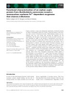
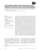
Figure 1: Transmission flow during a round. Filled box: sink; filled
circles: cluster heads; circles: noncluster-head nodes.
the conclusions a re drawn in the final section. The appendix
presents the new CH election algorithm proposed in this pa-
per which shows very good performance improvement with
respect to the protocols previously presented in the litera-
ture: the algorithm description is reported in the appendix
to make the paper more readable.
2. REFERENCE SCENARIO AND APPLICATION
2.1. Reference scenario
The reference scenario we assume consists of N
TOT
sensors
randomly and uniformly distributed over a square area (hav-
ing side M) and a sink located at a given distance d from the
center of the square, as show n in Figure 1. The network must
be able to provide the information detected by nodes to a
sink that periodical ly (every T
R
seconds) broadcasts a short
packet that we call “start” and waits for the replies from the
nodes. We denote by “round” the period of time between two
successive start packets sent by the sink. During each round,
all sensors should send their information to the sink.
The wireless channel is assumed to be characterized
by random fluctuations that will be modeled as Gaussian
distributed when being in logarithmic scale. A distance-
dependent path loss is also considered. The model is m oti-
vated by the presence, in many cases for WSNs, of obstacles
(ground, foliage, cars, human bodies, depending on the ap-
plication).
2.2. Reference application and motivation for the
choice of LEACH and CSMA
This work, though presenting ideas, approaches, and results
which are much more general, has been inspired by a spe-
cific application: the monitoring of a car parking area where
nodes sense the presence of cars and interact to communi-
cate to a sink, which provides information to cars entering
the parking area about the better way to reach the closest
free slot. Other specific applications that can be considered
are based, for example, on the estimation of a target multi-
dimensional process such as, seismic waves through acoustic
sensors arrays, the ground temperature variations in a small
volcanic site, or structural monitoring of buildings, by means
of samples captured by nodes randomly and uniformly dis-
tributed. Samples are then transmitted to a sink with a self-
organizing and distributed routing strategy.
As for network aspects, routing algorithms for WSNs can
be classified into three categories: multihop flat, hierarchical,
and location-based [24]. In the first category, each node plays
the same role and sensors collaborate to perform the sensing
task. The second category, instead, refers to protocols w here
sensors a re organized in clusters, where particular tasks are
assigned to cluster heads; thus, nodes have not all the same
role in the network [25, 26]. Finally, in the third kind of pro-
tocols, sensors exploit the knowledge of their position in the
network, obtained, for example, through GPS. The multihop
flat protocols may include scalability issues, whereas the hi-
erarchical protocols (unless the number of levels of the hier-
archy is unlimited) can be applied only in those cases where
the maximum distance between nodes and the sink is not too
large. We will set values of d and M not larger than 100 mt, so
cluster-based algorithms like those belonging to the LEACH
family represent a good choice.
Concerning MAC, the selection of a protocol belonging
to the families of collision-free or collision-prone strategies
requires suitable comparison between the time elapsing be-
tween two start packets T
R
and the time coherence of the en-
vironment T
coh
which is a measure of how slow or fast the
channel attenuation fluctuates.
In fact, when T
coh
is much larger than T
R
,asuitable
scheduling of transmissions, which requires extra signalling
between nodes, can be kept fixed for many rounds, thus re-
ducing the impact of the related energy wasted on network
lifetime. On the other hand, if this condition does not oc-
cur, the channel tends to be independent in different rounds,
and a collision-free protocol which tries to schedule trans-
missions in order to avoid collisions becomes energy ineffi-
cient since the extra signalling to manage the scheduling is
required at each round.
The application we consider is characterized by values of
T
R
which are larger than, or of the same order as, T
coh
,and
the natural choice in this case is CSMA.
In particular, we will consider two different cases: the first
with T
coh
T
R
(scenario 1) and the second with T
coh
T
R
(scenario 2); more precisely, in the former case, the chan-
nel fluctuations are completely uncorrelated at each round,
whereas, in the second scenario, we assume a block-fading
model, where the random variables characterizing the prop-
agation channel remain constant for two subsequent rounds,
and then change according to a memoryless process.
The following assumptions concerning the application,
are also made.
(i) Nodes and sink are still (no mobility).
(ii) Nodes do not know their position in the area.
(iii) Each node is aware of the sink position with respect to
a given reference coordinate system; in particular (as
Cross-Layer Design of an Energy-Efficient Cluster Formation Algorithm 675
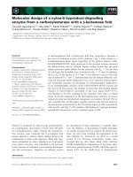
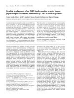
Start i +1Start i
T
R
t
T
CF
T
IC
T
TS
T
CF
Figure 2: Time axis showing the three phases of the routing pro-
tocol. Clusters are formed in the cluster formation (CF) period, the
CHs collect the packets sent by non-CH nodes in the intracluster
(IC) period while CHs transmit toward the sink in the TS period.
described in the appendix), the sink includes the infor-
mation about its position in the trigger, so that nodes
are aware of it.
(iv) Each node can use power control to vary the transmit
power.
3. THE ROUTING PROTOCOL—LEACH B+
We propose a new routing strategy which combines LEACH
B[18] with a simple single-path routing protocol, which in-
cludes the direct transmission to the final sink, without pass-
ing through CH nodes, when it is energetically efficient.
Moreover, a new CH election algorithm is proposed. Two
different versions of our new algorithm are suitably designed
for scenario 1 and 2; we name them LEACH B+ v1 and
LEACH B+ v2, respectively.
In case of LEACH B+ v1, a clustering protocol based
on two phases, performed whenever nodes receive the start
packet from the sink, is designed.
(1) Setup
Clusters are formed according to a two-step procedure: a dis-
tributed self-election algorithm is run by nodes in order to
elect the cluster heads (CHs), then each CH broadcasts a
packet informing of its role and those nodes that did not elect
themselves as CHs select the cluster to belong to, or decide to
transmit directly to the sink. Details are given below.
(2) Transmission
Each non-CH node, belonging to a given cluster, transmits its
packet to the respective CH, which, in turn, sends all packets
received from the cluster, plus the one it generated, to the re-
mote sink. Alternatively, nodes transmit directly to the sink.
InLEACHB+v2,instead,thefirstphaseisperformed
once every two rounds, because nodes, which elected them-
selves as CHs, remain CHs for the following round and so
the CH election algorithm is not carried out at every round
(except for the case in which there are no CHs elected. In the
latter case, in fact, the CH election algorithm is performed at
the subsequent round, too). By using this strategy, CH nodes
have to transmit the initial broadcast packet only once ev-
ery two rounds, since the information about which sensors
are CHs remains unchanged for two rounds. As we will see
in Section 8, this version allows the decrease of energy con-
sumption.
All other aspects of LEACH B+, which will be described
in this section, and Sections 4–6, do not change in the two
versions (namely, v1 and v2).
In this paper, we also introduce a subdivision of the time
axis into three periods, one for each phase of the algorithm
(taking into account that the first phase is divided, on its
turn, into two phases), to reduce collisions between packets
(see Figure 2).
(1) T
CF
: during this p eriod, the start packet and CHs
broadcast packets are sent.
(2) T
IC
: non-CH nodes send their packets to the CHs.
(3) T
TS
denotes transmissions toward the sink.
3.1. Cluster-head selection algorithm
LEACH B+ forms clusters by using a distributed algorithm,
where nodes make autonomous decisions without any cen-
tralized control. When a node receives the start packet, it
decides whether or not to become a CH for the cur rent
round. This algorithm allows the election of a certain num-
ber of CHs, on average equal to
N. Being a CH node is much
more energy intensive than being a non-CH node. Therefore,
LEACH incorporates a randomized rotation of the CH role
among sensors to avoid draining the battery of a particular
set of sensors in the network [10]. Ensuring that all nodes be-
come CHs the same number of times, each node will be CH
once in N
TOT
/
N rounds on average. The rationale behind the
determination of the value of
N is described in the appendix
through suitable analytical formulation.
To do this, we consider an indicator function C
p
(i)de-
termining whether or not node p, at the ith round, has been
a CH in the most recent R
∗
=N
TOT
/
N−1 rounds (i.e.,
C
p
(i) = 0ifnodep has been a CH and 1 otherwise), where
x stands for the largest integer less than or equal to x.The
decision to become or not a CH is made by node p choosing
a random number b etween 0 and 1. If the number is less than
a threshold T
p
(i), the node becomes a CH. The threshold is
set as
T
p
(i)
=
0, C
p
(i)=0,
N
p
N
TOT
−
N
p
·
i mod N
TOT
/
N
p
, C
p
(i)=1, R<R
∗
,
1, C
p
(i)=1, R=R
∗
,
(1)
where R is a counter incremented at each round and set to
zero whenever it reaches R
∗
or when the node becomes CH,
while
N
p
is set equal to
N initially. In the appendix,
N is
evaluated in a more realistic way wi th respect to LEACH B.
Therefore, according to (1), the mechanism which allows the
rotation of the CH role is the following: every node starts
with C
p
(i) = 1, so it has the possibility to become CH; when a
node elects itself CH, C
p
(i) is set to zero and the node cannot
become CH for R
∗
rounds; after that, C
p
(i)issettoone,so
the node can become CH again with probability that grows
676 EURASIP Journal on Wireless Communications and Networking
with i; while if a node does not elect itself CH for R
∗
consec-
utive rounds, it is forced to be a CH for the current round by
setting T
p
(i) = 1.
In conventional LEACH [10],
N is a fixed value and it is
determined a priori. In LEACH B+, we propose a new adap-
tive strategy to choose the CHs election frequency, varying
N
for each node in such a way that we consider the energy dis-
sipation of each node the last time it has assumed the role of
CH. As can be seen in [18], this st rategy improves network
lifetime.
If we consider an average situation, each CH has to send
N
TOT
/(
N + 1) (as we will see below the (
N +1)thcluster
is formed by nodes that choose to transmit to the sink via
a direct link) packets to the final sink with an energy con-
sumption that is dependent on its position, plus the energy
required to receive N
TOT
/(
N +1)− 1 packets from non-CHs
that belong to the cluster. As explained in Section 5,weas-
sume that the transmission power of each node (either CH
or non-CH) is controlled adaptively in order to guarantee an
adequate received power at the destination nodes with the
minimum required energy. Therefore, since the energy dissi-
pated by each CH is dependent on its position with respect to
the sink, we can evaluate the worst and the best case in terms
of energy consumption that is useful to perform our adaptive
strategy,
E
CH-far
=
N
TOT
N +1
− 1
E
R
+
N
TOT
N +1
E
T-far
,
E
CH-close
=
N
TOT
N +1
− 1
E
R
+
N
TOT
N +1
E
T-close
,
(2)
where
(i) E
R
is the energy spent to receive a packet (see
Section 6);
(ii) E
T-far
and E
T-close
are the energ i es spent to transmit a
packet, considering two different transmission ranges:
the distance between the sink and the farthest point of
the network D
max
, and that between the sink and the
closest one d − M/2.
Starting from the average of these energies
E
CH-avg
=
E
CH-far
+ E
CH-close
2
,(3)
we fix two different thresholds as follows:
E
CH-sup
= E
CH-avg
+0.6 · E
CH-avg
,
E
CH-inf
= E
CH-avg
− 0.6 · E
CH-avg
.
(4)
If the energy dissipated by node p the last time it as-
sumed the role of CH is larger than E
CH-sup
, the value of
N
used by node p,
N
p
, is decreased by 1, so that this node will
have smaller probability to become CH in the next rounds.
At the opposite, if this energy is smaller than E
CH-inf
,
N
p
is
increased by 1. Finally, if the energy dissipated is between the
two thresholds, the value of
N
p
does not change.
Particular attention must be paid on the cluster election
phase. In fact, the CH election should guarantee the mini-
mum energy consumption by means of the cluster-head ro-
tation algorithm presented. In order to assess the validity of
the algorithm proposed, several simulations have been p er-
formed. As a result, we can state that in LEACH B+, the ma-
jority of CHs are located, on average, on a circumference cen-
tered in the sink, and having radius equal to D
max
/2, which is
clearly an efficient condition from the energy consumption
viewpoint.
3.2. Cluster formation algorithm
Concerning cluster formation, each node chooses its CH by
evaluating the energy dissipated in the complete path be-
tween itself and the final sink, via the CH, for the transmis-
sion of its packet.
The start packet sent by the sink contains the information
about the power used for its transmission, so every receiv-
ing node can compute the loss between itself and the sink.
The broadcast packet sent by each CH includes the value
of power used for this transmission and the loss estimated
previously.Everytimeanon-CHnodereceivesabroadcast
packet, it estimates the total path loss between it and all the
CHs whose packets have been successfully detected by the
node, and reads the loss between the CH and the sink. Ev-
ery node selects the path characterized by the smallest total
path loss, considering also the possibility to transmit directly
its packet to the sink without passing through any CH. So ev-
ery non-CH selects the link (through the CH or not) which
corresponds to the lowest path loss.
Finally, if a non-CH node does not receive any broadcast
packets correctly, it is forced to transmit directly to the sink.
4. THE MAC PROTOCOL PROPOSED
The access to the wireless channel is controlled through a
CSMA protocol, whose mechanism has been inspired by the
IEEE 802.11 standard [23]. According to this protocol, each
node, before transmitting, invokes a carrier-sensing mecha-
nism to determine the busy/idle state of the channel. After
the sensing phase, one out of two situations may occur.
(1) Channel free: the node generates a random backoff pe-
riod T
b
for an additional deferral time before transmit-
ting its packet.
(2) Channel busy: the algorithm is different for a non-
CH or a CH. The former stops sensing and moves to
a sleeping state, where it remains till the end of the
packet transmission; therefore, the node turns off and
it preserves energy. In fact, we assume that in each
transmitted packet, there is a duration field that in-
dicates how long the remaining transmission w ill be,
so when a node receives a packet destined to another
node, it knows for how long it cannot transmit [20]. In
the latter case, the node keeps on, because it could re-
ceive packets from other nodes belonging to its cluster.
Cross-Layer Design of an Energy-Efficient Cluster Formation Algorithm 677
S
APP
T
AMP
P
T
A
T
G
T
U
APP
R
P
R
A
R
G
R
D
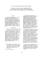
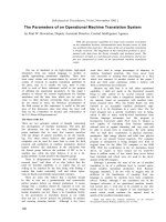
Figure 3: Transmission system block diagram.
The duration of the carrier-sensing phase T
s
is not fixed; it is
considered to be random and given by
T
s
= (1 + r) · DIFS, (5)
where the following exist.
(i) Distributed interframe space (DIFS) is the minimum
sensing length and we take it equal to the data trans-
mission time; assuming a negligible propagation delay,
as is usually done for sensor networks [20], the data
transmission time is the time during which the packet
occupies the channel and is given by the r a tio between
the packet size z and the bit rate R
b
.
(ii) r is a random number drawn from a uniform distribu-
tion over the interval [0, 1).
The choice of a random sensing time [20] allows the reduc-
tion of packet collision probability; there are two possible
causes of collision: two or more nodes could select the same
value of r, so they end sensing at the same time and transmit
simultaneously, or a node is not able to perceive a communi-
cation in the channel and could decide to transmit its packet
though the channel is busy (hidden node problem). By fixing
a minimum received power for a successful channel sensing
P
Smin
, in fact, a node which receives a packet with a power
smaller than such value does not “hear” the transmitter.
We assume a packet is captured by the receiver, even in
case of packet collisions if
P
r0
N
i=1
P
ri
>α
0
,(6)
where
(i) P
r0
is the power received from the useful signal;
(ii) P
ri
is the ith interference power;
(iii) Nis the number of colliding packets;
(iv) α
0
is the capture threshold which we set equal to 3 dB.
When condition (6) is not fulfilled, the packet is lost and
the receiving node requires the packet retransmission. An
acknowledge mechanism is not provided in this algorithm,
because the t ransmission and the reception of these packets
cause a n increase of the energy spent. Thus, we consider only
the use of retransmission requests, when nodes receive wrong
packets.
To minimize collisions during contention between multi-
ple nodes, as mentioned above, we introduce a backoff algo-
rithm, namely the exponential backoff algorithm adopted in
the IEEE 802.11 MAC protocol [23]. According to this algo-
rithm, nodes, once the sensing phase has ended, in the case of
free channel do not transmit their packets immediately, but
only after a random backoff time given by
T
b
= r
c
· DIFS, (7)
where r
c
is a random integer drawn from a uniformly dis-
tribution over the interval [0, CW], where CW is the con-
tention window value, that is, an integer within the range
of values CW
min
and CW
max
(CW
min
<CW<CW
max
).
We used the 802.11 standard values, so CW
min
= 7and
CW
max
= 255. The contention window parameter will take
the initial value of CW
min
. Then, in case of collision, CW is
augmented and the new value is computed as
CW = CW
min
· 2 −1. (8)
So, there is an exponential increase of the contention window
value up to CW
max
, or till a packet is correctly received. In
both cases, CW will be reset to CW
min
.
The performance of CSMA protocols are mainly affected
by the hidden node problem and the amount of data trans-
mitted by nodes to the CHs. First of all, we want to point
out that the random changing of the CHs can mitigate the
hidden terminal problem. In fact, in every round in LEACH
B+ v1, or every two rounds in LEACH B+ v2, the clusters
change according to the cluster-head election algorithm de-
fined. Therefore, if a node is unfortunately hidden during a
round, this does not preclude that this situation changes in
the following rounds. As far as the impact of the MAC pro-
tocolonnetworkperformanceisconcerned,wehaveana-
lyzed its behavior for different packet sizes z.Inparticular,
an increase of the packet size from 127 to 1016 bits corre-
sponds to an expected decreasing of the network lifetime due
to the augmented number of collisions, and a doubling of the
packet loss rate.
5. PHYSICAL ASPECTS
5.1. Transmission system
In this section, we describe the transceiver scheme adopted
for each node, the ra dio propagation channel, and the power
required for the transmission. The block diag ram of the
transmitting and receiving parts that are considered in our
analysis is reported in Figure 3. S and U are the source of bits
and the final user, respectively. The block APP
T
is composed
ofacoder,amodulator,andanup-converter,AMPrepre-
sents the power amplifier for the transmission, while APP
R
is composed by a down-converter, a demodulator, and a de-
coder. Finally, the blocks A
T
, A
R
represent the attenuations
due to the connections by transmitting and receiving anten-
nas, respectively, while G
T
and G
R
are the antenna gains.
678 EURASIP Journal on Wireless Communications and Networking
As far as propagation is concerned, we assume a statis-
tic channel chara cterized by a Gaussian distribution of loss,
when measured in dB,
L(dB) = P
T
(dBm) − P
R
(dBm), (9)
where P
T
and P
R
represent the generic transmit and receive
powers,respectively.ThelogarithmicvalueofL has mean de-
pending on link distance, antenna gains, and so forth. More
precisely, we assume the following expression for loss at dis-
tance D:
L(dB) =
4πf
c
d
0
/c
2
D/d
0
α
G
ant
(dB) + S, (10)
where
(i) f
c
(Hz) is the carrier frequency, c(m/s) is the speed of
light, d
0
(m) is a reference distance, and α is the path
loss exponent;
(ii) G
ant
is given by
G
ant
=
G
T
G
R
A
T
A
R
; (11)
(iii) S is a Gaussian random variable, with variance σ
2
and
zero mean.
In this paper, we fix two power thresholds: the smallest
one is the minimum receiver sensitivity P
Smin
and the other
is the receiver sensitivity P
Rmin
. A packet is correctly detected
whenever P
R
is larger than P
Rmin
and it is “heard” when P
R
is
larger than P
Smin
.
As far a s the transmission scheme is concerned, we as-
sume a binary phase-shift keying (BPSK) modulation with a
BCH(127, 50,13) code, that is, with packet length z = 127
and information bits k = 50, able to correct up to t = 13 bits.
5.2. Packet error probability
Assuming a transmission scheme based on BPSK modula-
tion, the two thresholds P
Rmin
and P
Smin
can b e derived start-
ing from the bit error probability [27]
P
eb
=
1
2
erfc
E
b
N
0
R
c
, (12)
where E
b
is the received energy per information bit, R
c
=
k/n = 0.394 is the coding rate, and
W =
P
R
N
0
R
b
(13)
is the signal-to-noise ratio at the receiver input. In particu-
lar, N
0
is the one-sided power sp ectral density of the additive
white Gaussian noise (AWGN) which depends on the noise
figure F of the receiver, that is,
N
0
= K
B
FT
0
, (14)
Table 1: Reference parameters.
Parameter Value Parameter Value
f
c
5GHz R
b
50 Mbps
d
0
0.2m P
ep
10
−2
α 2.5 W
R
5.12 dB
σ 3dB W
S
3dB
G
ant
−20 dB P
Rmin
5.92 pW
F 10 dB P
Smin
3.4pW
η
amp
0.8 P
OUT
SN
0.01
P
APP
T
3.63 mW P
OUT
NS
0.05
P
APP
R
11.13 mW P
OUT
Br
0.2
P
APP
S
5.565 mW t
ACT
0.5
t
CF
0.01 t
IC
0.25
where K
B
is Boltzmann’s constant and T
0
= 290 K. Consid-
ering packets of z bits, packet error probability is then given
by
P
ep
=
z
i=t+1
z
i
P
i
eb
(1 − P
eb
)
z−i
. (15)
Now, for a given value of P
ep
,wecanderiveP
eb
, and then
from (12)–(14), the corresponding received power can be
evaluated. In particular, by fixing a packet error probability
of P
ep
= 10
−2
, we derive the receiver sensitivity as
P
Rmin
= W
R
N
0
R
b
, (16)
where W
R
is the signal-to-noise ratio needed to detect a
packet. By fixing a signal-to-noise ratio equal to 3 dB, the
minimum receiver power P
Smin
required to “hear” a packet
is derived. All the parameters involved in the derivation of
these two power thresholds are reported in Tabl e 1.
Having fixed the two aforementioned thresholds, the be-
havior of nodes when they receive the start packet is as fol-
lows.
(i) If P
R
<P
Smin
, the node cannot perceive the packet, and
therefore it does not transmit its own packet for that
round.
(ii) If P
Smin
<P
R
<P
Rmin
, it perceives the start packet but it
cannot compute the path loss between it and the sink,
since the infor mation about the transmit power used
by the sink cannot b e read.
(iii) If P
R
>P
Rmin
, it can compute the loss.
5.3. Power control
Now we consider the transmission power used in the differ-
ent phases of the LEACH B algorithm.
The start packet is transmitted using a value of power
given by
P
Tmax
=
P
Rmin
4πf
c
d
0
/c
2
D
max
/d
0
α
M
f
G
ant
, (17)
Cross-Layer Design of an Energy-Efficient Cluster Formation Algorithm 679
where the transmission range D
max
is the distance between
the sink and the point in the scenario farther from it (see
Figure 1). M
f
is a fade margin suitably introduced to keep
under control the probability of packet failure owing to the
random fluctuations of the channel; it can be written as
M
f
=
√
2σ · erfc
−1
(2P
OUT
), (18)
where P
OUT
is the maximum outage probability which de-
pends on the type of transmission. The outage probability is
the probability that the packet reception fails. For the trans-
mission of the start packet, we use P
OUT
= P
OUT
SN
.The
broadcast CHs messages are transmitted w ith
P
Br
=
P
Rmin
4πf
c
d
0
/c
2
d
broadcast
/d
0
α
M
f
G
ant
, (19)
where M
f
is given by (18)withP
OUT
= P
OUT
Br
and d
broadcast
is
the area diagonal. As we explained, nodes do not know their
position in the network, so they must behave like they were
in the worst case.
In both cases (start and broadcast packets), the received
power at the maximum distance is given by
P
R
(dBm) = P
Rmin
(dBm) + M
f
(dB) − S. (20)
Note that, depending on the value of the margin M
f
,some
packets can be lost owing to the channel fluctuations.
During each round, we assume a stationary channel, so
losses between CHs a nd non-CHs do not change. With this
assumption in mind, every node can transmit its packet to
the CH by using the minimum power that allows its correct
reception. Therefore, the transmit power used by a generic
non-CH node to send its packet to the relevant CH is
P
Tx
= P
Rmin
· L, (21)
where L is the path loss between the CH and the node that is
transmitting .
Finally, we consider the transmission power of the mes-
sages sent by the CHs to the sink, or any nodes directly tra ns-
mitting to the sink. If these nodes succeeded in computing
the loss between them and the sink, by extracting the infor-
mation from the start packet regarding its transmit power
and measuring the received power level, their transmit power
is set according to (21)whereL, in this case, is the path loss
between the transmitting node and the sink. If such node was
not able to estimate L, it will transmit using the power level
P
Tmax
. In this case, M
f
is given by (18)withP
OUT
= P
OUT
NS
.
All parameter values not specified in the text of the paper
are reported in Ta ble 1 .
6. ENERGY CHARACTERIZATION
The central problem for sensor networks is energy consump-
tion. It is important to estimate the energy spent, during each
round, by all nodes, when they transmit, receive, or sense the
channel.
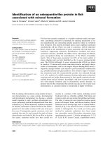
Start i +1Start i
t
T
CF
T
IC
T
TS
T
ACT
ON
15 DIFS
DIFS
OFF ON OFF ON
T
ACT
ON
···
Figure 4: Time axis for each node in the ON/OFF mode.
Transmission
The energy dissipated for the packet transmission depends
on the value of the transmission power
E
T
= z ·
P
APP
T
R
b
c
+
P
T
R
b
c
· η
amp
, (22)
where (see Figure 3)
(i) P
APP
T
includes the power dissipated in the baseband,
oscillator, frequency synthesizer, mixer, filters, and so
forth;
(ii) P
T
/η
amp
is the power dissipated within the power am-
plifier, where P
T
is given by (17), (19), or (21), accord-
ing to the specific cases;
(iii) η
amp
≤ 1 is the transmitter amplifier efficiency;
(iv) R
b
c
= R
b
/R
c
is the coded bit rate.
Reception and Sensing
In the radio receiver model we use, there is no difference be-
tween the energy levels dissipated during reception or sens-
ing [20]. The energy needed to keep the node on is given by
E
sens
= P
APP
S
· T, (23)
where P
APP
S
represents the power dissipated during the sens-
ing phase (see Table 1 )andT is the time interval during
which the node senses the channel.
In particular, the energy consumed to receive a packet is
E
R
= z ·
P
APP
R
R
b
c
, (24)
where P
APP
R
represents the power dissipated during the re-
ceiving phase.
Note that in case nodes do not know when the following
start packet will arrive, we have a high energ y consumption
due to the fact that nodes should be on between the end of a
round and the beginning of the following one.
As we can see in Section 8,weinvestigateperformancein
terms of network “lifetime.” To extend the nodes lifetime, we
introduced the ON/OFF modality (Figure 4)inwhich,after
the start packet’s arrival, nodes stay on for a certain inter val
of time denoted as T
ACT
and then they turn off and on alter-
natively till the follow ing start. In particular, we have chosen
680 EURASIP Journal on Wireless Communications and Networking
(i) the duration of the ON phase equal to DIFS,
(ii) the duration of the OFF phase equal to 15 · DIFS,
according to suitable considerations, not reported for the
sake of conciseness.
To be sure that a star t packet is detected by each node
regardless of the ON/OFF mechanism, the sink must t rans-
mit sixteen sequential starting packets so that every node is
able to receive at least one of these. Note that this requires
that the sink has no energy consumption problems. T hrough
this modality, we obtain a significant improvement of perfor-
mance in terms of system lifetime.
As mentioned in Section 3, T
ACT
is divided in the three
periods of duration T
CF
, T
IC
,andT
TS
.
7. CROSS-LAYER DESIGN
7.1. Scenario 1—CLD v1
To improve network performance, we introduce a modi-
fied version of LEACH B+ v1, based on the CL par adigm,
denoted as CLD v1, where interactions between physical
and MAC layers and MAC and network layers are intro-
duced.
For the interaction between physical and MAC layers, a
power control algorithm is proposed which accounts for the
number of retransmissions required. As mentioned, when
nodes, either CHs or non-CHs, do not know the loss be-
tween themselves and the sink, they transmit with a high
power level (obtained by assuming that the node is at a dis-
tance D
max
from the sink). Since in this case nodes waste a
lot of energy, we impose that they transmit to the sink by
using a power equal to P
Tmax
/2, while they use P
Tmax
when
they receive a retransmission request by the sink. In this way,
the MAC layer affects the physical layer, namely the transmit
power algorithm.
Concerning the CL interactions between the MAC and
network layers, we use, once again, the number of retrans-
missions requested to influence the CH election algorithm
for the following rounds. In Section 3.1, we stated that the
value of
N used by a node p,
N
p
, is decreased by 1 when the
energy dissipated by the node the last time it assumed the role
of CH is larger than E
CH-sup
, a nd it is increased by 1 when the
energy spent is less than E
CH-inf
. A possible CL interaction to
reduce the energy waste consists in increasing and decreasing
N
p
, by considering not only the energy dissipated, but also
the number of retransmissions requested by the sink to a CH
in the last round it assumed the role of CH. In particular,
N
p
is increased when the energy spent is low and the nodes have
received less than 2 retransmission requests from the sink; at
the opposite,
N
p
is decreased when the CH has dissipated a
lot of energy and has received more than 3 retransmission
requests. By increasing
N
p
, the probability that the node will
be CH for the next rounds increases and, in this way, this op-
portunity is given only to nodes that are in a good location
with respect to the sink, either in terms of energy expense, or
in terms of collisions.
Table 2: Round when the first node expires.
LEACH B LEACH B+ v1
Nodes N
round
/Joule N
round
/Joule
30 16949 37284
25 22560 41985
20 29480 45143
15 32370 48205
10 42680 51550
5 48410 59375
0 56150 63900
7.2. Scenario 2—CLD v2
In this case, as stated previously, we assume that the loss be-
tween two nodes remains unchanged for two rounds; a suit-
able protocol design can take advantage of this. We define
here a new version of LEACH B+, namely CLD v2, which in-
cludes all the techniques already introduced in CLD v1 plus
some additional features: the information about the request
of retransmissions obtained at the first of the two rounds is
used at the second round to change the structure of the clus-
ter. At the first round, in fact, every non-CH node records
the value of the loss between itself and the sink and the total
losses between itself and the sink, passing through the CHs.
At the beginning of the second round, if it has received one or
more retransmission requests, it changes the cluster to which
it belongs to. It will choose the CH, or also the sink, which
corresponds to the smallest loss, avoiding the previous CH
considered. No adaptive strategy is performed between the
second and the third rounds, for example, because, owing to
the fact that the channel changes, in the third round, there is
a new election of the CH nodes a nd new clusters are formed.
Moreover, when a non-CH node belonging to a certain
cluster receives a retransmission request from its CH, to re-
duce the packet losses, it transmits its packet directly to the
sink, without passing through the CH. So, nodes can change
the cluster they belong to according to the number of retrans-
missions that occurred within the cluster. However, the direct
transmissions to the sink are very energy expensive, in partic-
ular for those nodes that are farther from the sink, so this CL
protocol, even if advantageous in terms of packet loss rate, is
expected to worsen network lifetime.
8. NUMERICAL RESULTS
We show the performance results obtained by means of a
simulator implemented on an OMNET++ platform [22]. All
simulation parameters related to a network with M = d =
100 mt are reported in Ta ble 1 . All values of time intervals
are normalized with respect to T
R
; so, for example, t
ACT
is
equal to T
ACT
/T
R
, and so forth.
8.1. Improvement with respect to LEACH B
First of all, in Tabl e 2, we compare the round when the first
node expires for LEACH B [18] and the new LEACH B+ v1
Cross-Layer Design of an Energy-Efficient Cluster Formation Algorithm 681
76543
×10
4
35
30
25
20
15
10
5
0
Number of nodes still alive
N
round
/Joule
LEACH B+ v1
CLD v1
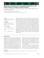
Figure 5: Number of nodes still alive as a function of the number
of rounds, normalized with respect to energy.
protocol by showing the clear improvement provided by our
proposal. Note that in Ta b le 2 as well as in the following fig-
ures, the value of the number of rounds is normalized with
respect to the value of energy which equipped the sensors
initially.
8.2. Scenario 1
In this section, we illustrate a comparison between the per-
formance obtained in scenario 1 with the LEACH B+ v1 pro-
tocol and with CLD v1 (i.e., without or with CL approach
implemented, resp.).
In Figure 5, we compare the network lifetime of the two
protocols, considering a network of N
TOT
= 30 nodes. In par-
ticular, we show the number of nodes still alive as a function
of time, expressed in terms of number of rounds. The figure
shows that the CL approach allows an increase of network
lifetime. In Figure 6, we show the round when the first node
expires, as a function of N
TOT
; this parameter increases by in-
creasing N
TOT
. As we can notice, the improvement due to the
CL approach is kept even by varying N
TOT
(i.e., the density
of nodes).
Now, we consider the packet losses. The causes for these
losses are the following.
(1) Fading: when P
R
<P
Rmin
, the packet is lost; the mar-
gin M
f
is set in order to control the packet loss probability
on each link, but the total packet loss rate in the network is
different, as it is a combination of the events on the different
links.
(2) Collisions: notwithstanding the use of a retransmis-
sion mechanism, some packets could be lost. In fact, when a
node transmits, it is not able to perceive a packet directed to
itself, so it cannot ask for retransmission.
In Figure 7, we show the packet loss rate as a function of
N
TOT
for the two protocols. The losses increase, by increasing
5040302010
×10
3
47
44
41
38
35
32
Round at which the first node dies
N
TOT
LEACH B+
LEACH B+ with CLD
SL
Figure 6: Round when the first node expires as a function of N
TOT
.
N
TOT
, owing to the larger traffic. As we can see, the two pro-
tocols have about the same values of packet loss rate, so we
can conclude that CLD v1 improves network lifetime with-
out increasing the packet loss ra te.
Finally, in Figure 8, we show the round when the first
node expires as a function of
β =
P
APP
S
P
APP
R
(25)
to show that there is a strong dependence between network
lifetime and the power spent in the sensing state. In fac t, in
our protocol, the time during which sensors are in a sens-
ing state is high, so if in this state they spend the same en-
ergy as in the receiving state (β = 1), their life will be much
shorter.
8.3. Scenario 2
This section is dedicated to show the comparison between
LEACH B+ v2 and CLD v2.
Concerning network lifetime (see Figure 9 ), LEACH B +
v2 performs better than v1, because, in the former case, CH
nodes have to transmit half of the broadcast packets than in
the latter. However, when we introduce the CL strategy de-
scribed in Section 7.2,wehaveadecreaseofnetworklife-
time, owing to the fact that we increase the number of di-
rect transmissions to the sink, which are very expensive. This
protocol, however, allows a significant decrease of packet loss
rate (see Figure 10) either with respect to LEACH B+ v1 or
v2. So, in this scenario, the CL approach proposed, account-
ing for MAC protocol status at network level, provides ad-
vantages in terms of loss rate at the expense of energy effi-
ciency.
682 EURASIP Journal on Wireless Communications and Networking
5040302010
0.1
0.08
0.06
0.04
0.02
0
Packet loss rate
N
TOT
LEACH B+ v1
CLD v2
Figure 7: Packet loss rate as a function of N
TOT
.
10.80.60.40.20
×10
3
55
50
45
40
35
30
Round at which the first node dies
β
LEACH B+ v1
CLD v1
Figure 8: Round when the first node dies as a function of β.
9. CONCLUSIONS
In this paper, a CSMA-based WSN composed of several tens
of nodes uniformly distributed over a square area is ana-
lyzed by means of simulations taking into account the com-
plete stack of layers. We proposed four different versions
of LEACH B+, a new protocol presented here which out-
performs the other algorithms belonging to the same class
(LEACH), previously presented in the literature. LEACH B+
is a hybrid protocol which allows nodes to use a single-
or two-hop path towards the sink according to energy-
9876543
×10
4
35
30
25
20
15
10
5
0
Number of nodes still alive
N
round
/Joule
LEACH B+ v1
LEACH B+ v2
CLD v2
Figure 9: Number of nodes still alive as a function of the number
of rounds, normalized with respect to the energy.
5040302010
0.1
0.08
0.06
0.04
0.02
0
Packet loss rate
N
TOT
LEACH B+ v1
LEACH B+ v2
CLD v2
Figure 10:PacketlossrateasafunctionofN
TOT
.
related considerations. Moreover, the distributed algorithm
for cluster-head self-election has been suitably designed
starting from some novel analytical descriptions of the en-
ergy spent on the average at each round; this model was re-
ported in the appendix to make easier reading of the paper.
We introduced the CL paradigm, which is shown here to
improve performance. In particular, we focused on two dif-
ferent scenarios, characterized by two different values of the
ratio between T
R
and T
coh
. The two different CL approaches,
derived from the two scenarios, allow the improvement of
Cross-Layer Design of an Energy-Efficient Cluster Formation Algorithm 683
the network lifetime (scenario 1) or the packet loss rate (sce-
nario 2).
The paper jointly takes routing, MAC, physical, energy,
and propagation aspects into account, and this makes the
description of the model used rather complex. Owing to
the many parameters of the model, the results shown rep-
resent a sample among the many found by the authors, but it
was found out that the conclusions drawn can be considered
more general and applicable to other sets of input parame-
ters.
APPENDICES
A. COMPUTATION OF
N
N is chosen in order to minimize the total transmission en-
ergy, which is the sum of the energies dissipated by each
node, CH and non-CH, in a round.
We assumed that there are N
TOT
nodes distributed uni-
formly in an M × M region. If
N nodes became CHs, there
would be
N + 1 clusters, because we consider also the cluster
formed by nodes which transmit directly to the sink. For the
purpose of the determination of
N, we assume that all
N +1
clusters are equally loaded, so in every cluster, there are on
average N
TOT
/(
N + 1) nodes (one CH and N
TOT
/(
N +1)− 1
non-CH nodes).
The total energy spent in a round is given on the average
by
E
TOT
= E
CH
·
N + E
non-CH→CH
· N
non-CH→CH
+ E
non-CH→S
· N
non-CH→S
,
(A.1)
where
(i) E
CH
is the energy dissipated by each CH;
(ii) E
non-CH→CH
is the energy dissipated by each non-CH
which chooses a CH to transmit to and
N
non-CH→CH
=
N ·
N
TOT
N +1
− 1
(A.2)
is the total average number of non-CHs which trans-
mit to a CH;
(iii) E
non-CH→S
is the energy dissipated by each non-CH
which chooses to transmit to the sink and
N
non-CH→S
=
N
TOT
N +1
(A.3)
is the number of non-CHs w hich transmit directly to
the sink, on the average.
Each CH dissipates energy to send the broadcast packet
to transmit its own packet and the packets of the other nodes
to the final sink and to make sensing (the energy spent to
receive packets can be neglected). We assume an average
situation where the shadowing is not considered and we
suppose that there are not collisions in the system, thus we
do not consider the energy dissipated for the retransmissions.
Hence, the transmission energy dissipated by a CH at a given
round, on average, can be written as
E
CH
=
N
TOT
N +1
− 1
E
APP
T
+ bd
α
CH-S
Non-CH packets
+
E
APP
T
+ bd
α
CH-S
Own packet
+
E
APP
T
+ bd
α
broadcast
Broadcast packet
+
P
APP
S
· T
Sensing
,
(A.4)
where d
CH-S
is the distance between the CH and the external
sink, d
broadcast
is the distance between the CH and the farthest
point of the observed area, E
APP
T
= zP
APP
T
/R
b
c
is the energy
spent by the block APP
T
during a packet transmission, and b
is a constant that takes into account transmission parameters
f
c
, G
ant
, P
Rmin
, and so forth, according to (17). Finally, T is
the sensing period, which is set to T
ACT
. So, contrary to the
LEACH B protocol, we take into consideration also the en-
ergy spent for sensing, obtaining a more realistic evaluation
of
N.
Each non-CH node only has to transmit its packet to the
CH or to the sink and so the energy dissipated for each round
is
E
non-CH→CH
= E
APP
T
+ bd
α
p-CH
+ P
APP
S
· T,(A.5)
where d
p-CH
is the distance between the pth node and the
CH. Moreover,
E
non-CH→S
= E
APP
T
+ bd
α
p-S
+ P
APP
S
· T,(A.6)
where d
p-S
is assumed equal to D
max
, which represents the
worst case.
In many practical scenarios, the energy spent in the block
APP
T
in (A.4), (A.5), and (A.6) can be neglected, that is,
E
APP
T
bD
α
for every distance D.
As developed in [10], the expected squared distance from
a general node p to the CH is given on average by
E
d
2
p-CH
=
M
2
2π
N
,(A.7)
so that (A.5) can be approximated by
E
non-CH→CH
P
APP
S
· T + b
M
2π
N
α
. (A.8)
684 EURASIP Journal on Wireless Communications and Networking
Therefore, for each round, the total transmission energy
dissipated in the network is on average
E
TOT
=
N
N
TOT
N +1
bD
α
max
+ bd
α
broadcast
+ P
APP
S
T
+
N
N
TOT
N +1
− 1
·
P
APP
S
T + b
M
2π
N
α
+
N
TOT
N +1
·
P
APP
S
T + bD
α
max
;
(A.9)
however, considering that
N N
TOT
and 1
N,(A.9)can
be approximated as
E
TOT
=
N ·
bd
α
broadcast
+ P
APP
S
· T
+
N
TOT
N
bD
α
max
+ P
APP
S
· T
+ N
TOT
b
M
2π
N
α
+ K,
(A.10)
where K is a term that does not depend on
N. At this point,
the optimum number of CHs can be evaluated easily by set-
ting the derivative of E
TOT
performed w ith respect to
N to
zero . We obtain
N
2
· k
0
=
N
1−α/2
· k
1
+ k
2
, (A.11)
where
k
0
= bd
α
broadcast
+ P
APP
S
T,
k
1
=
N
TOT
bα
2
M
√
2π
α
,
k
2
= N
TOT
P
APP
S
T + N
TOT
bD
α
max
.
(A.12)
This equation can be solved only numerically. Note that each
node can determine its own optimum number of CHs, owing
to the fact that the values of the total number of nodes in
the network, the path loss exponent, the network size, the
distance considered in the transmission of broadcast packets,
and T
ACT
are contained in the trigger transmitted by the sink,
so they are known by nodes. Note that
N does not depend
on the distance between the CH and the final sink, so that
distance could not be known.
REFERENCES
[1] I. F. Akyildiz, W. Su, Y. Sankarasubramaniam, and E. Cayirci,
“A survey on sensor networks,” IEEE Commun. Mag., vol. 40,
no. 8, pp. 102–114, 2002.
[2] V. Rajaravivarma, Y. Yang, and T. Yang, “An overview of wire-
less sensor network and applications,” in Proc. 35th Southeast-
ern Symposium on System Theory (SSST ’03), pp. 432–436,
Morgantown, WVa, USA, March 2003.
[3] M. Tubaishat and S. Madria, “Sensor networks: an overview,”
IEEE Potentials, vol. 22, no. 2, pp. 20–23, 2003.
[4] C Y. Chong and S. P. Kumar, “Sensor networks: evolution,
opportunities, and challenges,” Proc. IEEE,vol.91,no.8,
pp. 1247–1256, 2003.
[5] X. Hong, K. Xu, and M. Gerla, “Scalable routing protocols for
mobile ad hoc networks,” IEEE Network,vol.16,no.4,pp.11–
21, 2002.
[6] P. Chen, B. O’Dea, and E. Callaway, “Energy efficient system
design with optimum transmission range for wireless ad hoc
networks,” in Proc. IEEE International Conference on Commu-
nications (ICC ’02), vol. 2, pp. 945–952, New York, NY, USA,
April–May 2002.
[7] A. Woo and D. Culler, “A transmission control scheme for me-
dia access in sensor networks,” in Proc. ACM/IEEE Inter n a-
tional Conference on Mobile Computing and Networking (Mo-
biCom ’01), pp. 221–235, Rome, Italy, July 2001.
[8] S. Lindsey, C. Raghavendra, and K. M. Sivalingam, “Data
gathering algorithms in sensor networks using energy met-
rics,” IEEE Trans. Parallel Distrib. Syst., vol. 13, no. 9, pp. 924–
935, 2002.
[9] W. B. Heinzelman, A. P. Chandrakasan, and H. Balakrishnan,
“Energy-efficient routing protocols for wireless m icrosensor
networks,” in Proc. 33rd Hawaii International Conference on
System Sciences (HICSS ’00), pp. 1–10, Maui, Hawaii, USA,
January 2000.
[10] W. B. Heinzelman, A. P. Chandrakasan, and H. Balakrishnan,
“An application-specific protocol architecture for wireless mi-
crosensor networks,” IEEE Transactions on Wireless Communi-
cations, vol. 1, no. 4, pp. 660–670, 2002.
[11] M. J. Handy, M. Haase, and D. Timmermann, “Low energy
adaptive clustering hierarchy with deterministic cluster-head
selection,” in Proc. 4th International Workshop on Mobile and
Wireless Communications Network (MWCN ’02), pp. 368–372,
Stockholm, Sweden, September 2002.
[12] A. Conti and D. Dardari, “The effects of nodes spatial distri-
bution on the performance of wireless sensor networks,” in
Proc. IEEE 59th Vehicular Technology Conference (VTC ’04),
vol. 5, pp. 2724–2728, Milan, Italy, May 2004.
[13] R. Verdone, “An energy-efficient decentralised communica-
tion protocol for a network of uniformly distributed sensors
polled by a wireless transceiver,” in Proc. IEEE International
Conference on Communications (ICC ’04), vol. 6, pp. 3491–
3498, Paris, France, June 2004.
[14] Y. Zhang and L. Cheng, “Cross-layer optimization for sensor
networks,” in Proc. New York Metro Area Networking Workshop
(NYMAN ’03), New York, NY, USA, September 2003.
[15] M. Conti, G. Maselli, G. Turi, and S. Giordano, “Cross-
layering in mobile ad hoc network design,” IEEE Computer,
vol. 37, no. 2, pp. 48–51, 2004.
[16] A. Safwat, H. Hassanein, and H. Mouftah, “Optimal cross-
layer designs for energy-efficient wireless ad hoc and sen-
sor networks,” in Proc. I EEE 22nd International Performance,
Computing, and Communications Conference (IPCCC ’03),pp.
123–128, Phoenix, Ariz, USA, April 2003.
[17] L C. Wang and C W. Wang, “A cross-layer design of cluster-
ing architecture for wireless sensor networks,” in Proc. IEEE
International Conference on Networking, Sensing and Con-
trol (ICNSC ’04), vol. 1, pp. 547–552, Taipei, Taiwan, China,
March 2004.
[18] A. De Pedri, A. Zanella, and R. Verdone, “An energy efficient
protocol for wireless ad hoc sensor networks,” in Proc. Au-
tonomous Intelligent Networks and Systems (AINS ’03),Menlo
Park, Calif, USA, June–July 2003.
Cross-Layer Design of an Energy-Efficient Cluster Formation Algorithm 685
[19] K. Sohrabi, J. Gao, V. Ailawadhi, and G. J. Pottie, “Protocols
for self-organization of a wireless sensor network,” IEEE Pers.
Commun., vol. 7, no. 5, pp. 16–27, 2000.
[20] W. Ye, J. Heidemann, and D. Estrin, “An energy-efficient MAC
protocol for wireless sensor networks,” in Proc. 21st Annual
Joint Conference of the IEEE Computer and Communications
Societies (INFOCOM ’02), vol. 3, pp. 1567–1576, New York,
NY, USA, June 2002.
[21] C. Buratti, A. Giorgetti, and R. Verdone, “Simulation of an en-
ergy efficient carrier sensing multiple access protocol for clus-
teredwirelesssensornetworks,”inProc. International Work-
shop on Wireless Ad-Hoc Networks (IWWAN ’04), Oulu, Fin-
land, June 2004.
[22] OMNeT++: Objective Modular Network Testbed in C++,
.
[23] IEEE 802.11, “Standard for Wireless LAN Medium Access
Control (MAC) and Physical Layer (PHY) Specifications,”
IEEE Std 820.11-1997 edition, The Institute of Electrical and
Electronics Engineers, New York, NY, USA, 1997.
[24] J. N. Al-Karaki and A. E. Kamal, “Routing techniques in wire-
less sensor networks: a survey,” IEEE Wireless Communica-
tions, vol. 11, no. 6, pp. 6–28, 2004.
[25] M. Chatterjee, S. K. Das, and D. Turgut, “WCA: a weighted
clustering algorithm for mobile ad hoc networks,” Cluster
Computing, vol. 5, no. 2, pp. 193–204, 2002, Special Issue on
Mobile Ad Hoc Networking.
[26] S. Basagni, “Distributed clustering for ad hoc networks,”
in Proc. 4th International Symposium on Parallel Architec-
tures, Algorithms, and Networks (I-SPAN ’99), pp. 310–
315, Perth/Fremantle, Western Australia, Australia, June
1999.
[27] J. G. Proakis, Di gital Communications,McGraw-Hill,New
York, NY, USA, 3rd e dition, 1995.
Chiara Buratti was born in Rav enna, Italy,
on October 30, 1976. She received the M.S.
degree (summa cum laude) in telecommu-
nication engineering from the University of
Bologna, Italy, in 2003. Her research inter-
est is on wireless sensor networks, with par-
ticular attention to MAC, routing, and con-
nectivity issues, but she is also interested in
Bluetooth and ZigBee networks. Since 2003,
she h as been involved in Network of Excel-
lence in Wireless COMmunications (NEWCOM), the NoE born
within the Sixth Framework Program of the EC, and, in particu-
lar, she has been working on Project A, dedicated to wireless ad hoc
and s ensor networks.
Andrea Giorgetti was born in Cesena, Italy,
on November 5, 1974. He received the Lau-
rea degree in elect ronic engineering (with
honors) and the Ph.D. degree in electronic
engineering and computer science from the
University of Bologna, Bologna, Italy, in
1999 and 2003, respectively. In 2003, he
joined IEIIT-BO/CNR where he became a
researcher in 2005. His research interests in-
clude ultra-wideband systems, wireless sen-
sor networks, and MIMO systems. He is a Member of IEEE.
Roberto Verdone was born in Bologna,
Italy, in 1965. He received the Laurea de-
gree in electronic engineering (with honors)
and the Ph.D. degree in electronic engineer-
ing and computer science from the Univer-
sity of Bologna, Bologna, Italy, in 1991 and
1995, respectively. From 1996 to 2001, he
was a researcher with the Centre for Stud-
ies in Computer Science and Telecommu-
nication Systems of the National Research
Council (CSITE-CNR), University of Bologna, studying telecom-
munications. Since November 2001, he has been a Full Professor of
telecommunications with the University of Bologna. His research
activity is concerned with digital transmission, cellular and mo-
bile radio systems, wireless local area networks, wireless sensor net-
works, and intelligent transpor tation systems. From 1997 to 2000,
he participated in COST259 activ ities and acted as a coauthor of
the COST259 Final Report. He is the Chairman of the WG on net-
work aspects within the followup action COST273, and he is a Na-
tional Delegate for the action. He is a Member of IEEE and Exec-
utive Board Member of NEWCOM, the Network of Excellence in
Wireless COMmunications funded by EC through FP6.